A MAC Protocol for Multi-Channel Multi-Interface Wireless
Mesh Network using Hybrid Channel Assignment Scheme
*CHI-YU LI, AN-KAI JENG AND RONG-HONG JAN Department of Computer Science
National Chiao Tung University Hsinchu, 300 Taiwan
In recent years, Wireless Mesh Network (WMN) which uses a multi-hop configura-tion to extend the reach of the last-mile access to Internet has come into public notice. WMN improves network performance by the use of multiple orthogonal (non-overlap- ping) channels and multiple wireless interfaces. However, the Medium Access Control (MAC) protocol in IEEE 802.11 standard was designed and suited for only one channel and one interface. In this paper, we present a new MAC protocol which is specially de-signed for multi-channel and multi-interface WMNs. The proposed MAC protocol em-ploys a hybrid channel assignment strategy to solve the rendezvous problem and a wait-ing time scheme for updatwait-ing network allocation vectors (NAVs) to solve the multi- channel hidden terminal problem. Simulation results show that the proposed protocol can achieve a better utilization of both interfaces and channels.
Keywords: wireless mesh networks, multi-channel, multi-interface, MAC protocol,
channel assignment
1. INTRODUCTION
In recent years, WMN (Wireless Mesh Network), which uses a multi-hop configura-tion to extend the reach of the last-mile access to Internet, has come into public notice. It is based on IEEE 802.11 and deployed as mesh networks to provide a wireless distribu-tion system to let access points (APs) connect to Internet without wired connecdistribu-tion. WMN is a decentralized network and makes a set of APs interconnect via IEEE 802.11 links. It can dramatically reduce the cost of deploying a large-scale wireless local area network (WLAN) because of the absence of wired connection. For the satisfactory utili-zation of wireless broadband networks, WMN is characterized by the use of multiple orthogonal (non-overlapping) channels and multiple wireless interfaces.
The IEEE 802.11 standard has divided the available frequency into multiple or-thogonal channels. For instance, IEEE 802.11b provides 3 oror-thogonal channels in the 2.4 GHz spectrum, and IEEE 802.11a provides 12 orthogonal channels in the 5 GHz spec-trum. By assigning different channels to adjacent APs, the interference between APs in infrastructure networks can be reduced significantly. However, the current IEEE 802.11 standard allows only one channel to be used at a time. So if we can make use of all avail-able channels simultaneously and the interference can be further reduced, then the overall Received September 15, 2006; accepted February 6, 2007.
Communicated by Ten H. Lai, Chung-Ta King and Jehn-Ruey Jiang.
* This work was supported in part by the National Science Council of Taiwan, R.O.C., under grants No. NSC
95-2219-E-009-006, NSC 95-2219-E-009-008 and NSC 95-2752-E-009-005-PAE, and in part by the New Generation Broadband Wireless Communication Technologies and Applications project of Institute for
In-capacity will be improved. Nevertheless, the MAC protocol in the standard was designed and suited for only one channel and one interface. So, we need a new MAC protocol suited for multiple channels and multiple interfaces in WMN.
Wireless hosts have been typically equipped with one interface. There were many works [1-5] utilizing multiple channels with one interface because they consider that it is expensive to equip each host with multiple interfaces. However, with the trend of re-duced hardware costs [6] and in order to utilize multiple channels efficiently, there have been many proposed MAC protocols [7-14] using multiple interfaces.
There are two main problems encountered in all related works in designing multi- channel MAC protocols. The first problem is the rendezvous problem and the second is multi-channel hidden terminal problem. We will introduce them below.
(1) Rendezvous Problem
Before a pair of mobile hosts may communicate, each has to know the channel the other is on. Mo et al. [15] classified all multi-channel MAC protocols into two classes, single rendezvous and multiple rendezvous. In single rendezvous protocols [2, 3, 5, 10-12], the exchange of control packets occurs on only one channel, called the control channel, at any time. These protocols will result in the control channel saturation prob-lem because there is high contention on the control channel when the number of data channels is large. This problem makes the control channel to be a bottleneck and causes inefficient utilization of data channels. In multiple rendezvous protocols [1, 4, 7-9, 13, 14], mobile hosts can exchange control packets on many channels. The protocols of this class alleviate the rendezvous channel saturation problem but raise the challenge of en-suring the communicating pair being able to meet on the same rendezvous channel. In this paper, we propose a new multiple rendezvous protocol. It can ensure the communi-cating pair being able to meet each other.
(2) Multi-channel Hidden Terminal Problem
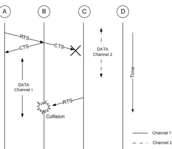
The IEEE 802.11 DCF mechanism can avoid the hidden terminal problem. However, in a multi-channel multi-interface environment, this problem is further complicated. Con-sider the scenario in Fig. 1. All mobile hosts are within the transmission range of each others. Host A wants to send a data packet to host B by sending an RTS packet on chan-nel 1 and then B responds with a CTS packet. During the negotiation of A and B, host C and host D are in transmission on channel 2 so that C can not hear the CTS packet from B and does not know the transmission occurs on channel 1. At the end of communication between C and D, C might initiate a communication with B and send RTS packet on channel 1. It will cause a collision at host B. The above problem is called multi-channel hidden terminal problem. Wu et al. [10] and So et al. [2] have already addressed this problem. Mobile hosts may listen to different channels and each host on selected channel can not hear the RTS and CTS packets sent on other channels so that it is difficult to use virtual carrier sense function to avoid the hidden terminal problem. There have been many researches which solve this problem with a separate control channel [10, 11], a time synchronization scheme [1, 2, 4] or a waiting delay [3, 5, 14].
Regarding the channel assignment scheme, there have been many results for multi-channel multi-interface MAC protocols. They can be classified into static chan-nel assignment strategy, dynamic chanchan-nel assignment strategy, and hybrid chanchan-nel
Fig. 1. Multi-channel hidden terminal problem.
assignment strategy. The static assignment strategy [7-9] assigns a channel to each in-terface permanently or for a long time. The benefit of this strategy is that there is neither the rendezvous problem nor the multi-channel hidden terminal problem, because each interface is fixed on a single channel. However, they require as many interfaces as chan-nels so that their hardware costs are increased. The dynamic assignment strategy allows each interface to be switched among multiple channels. The characteristic of this strategy is to utilize multiple channels with only a few interfaces. It is always used by the proto-cols, such as [1-5], in which each host is equipped with one interface. Although it can reduce hardware cost and power consumption, the rendezvous problem and the multi- channel hidden terminal problem would be more difficult to solve. Thus, the hybrid channel strategy is proposed to avoid the drawbacks of static and dynamic channel as-signment strategies. We will introduce the hybrid channel asas-signment scheme in detail in section 2.
In this paper, we propose a new MAC protocol for multi-channel multi-interface WMN. Our protocol is based on a hybrid channel assignment strategy. In this strategy, each node is equipped with a fixed interface and a switchable interface. The fixed inter-face must stay on a fixed channel for a long period and the switchable interinter-face can be switched among multiple channels. Each host can know the channels fixed on its neighbors and communicate with them by switching its switchable interface to those channels. Thus, this strategy can solve the rendezvous problem. In addition, we use a dynamic channel duration scheme to dynamically adapt the transmission time to the traffic loads and a dynamic waiting time assignment scheme to improve the utilization of interfaces. By this way, a better utilization of both interfaces and channels can be achieved.
The rest of the paper is organized as follows. Section 2 discusses the hybrid channel assignment scheme. In section 3, we present our MAC protocol for multi-channel and multi-interface wireless network. We describe our simulation model and discuss the re-sults of our simulation in section 4. Finally, we conclude this paper in section 5.
2. HYBRID CHANNEL ASSIGNMENT SCHEME
In recent years, the hybrid channel assignment strategy is proposed to improve the static and dynamic assignment strategies. In the hybrid channel assignment strategy, each host is equipped with multiple interfaces and there is no need of the time synchronization scheme. The strategy combines both static and dynamic assignment strategies. Some interfaces of a host use static assignment strategy and other interfaces use dynamic as-signment strategy. It employs the static asas-signment to solve the rendezvous problem to enable neighbors to find each other and employs the dynamic assignment to utilize mul-tiple channels efficiently. The hybrid channel assignment strategy can be further classi-fied into two categories. One is the common channel static assignment method and the other is the diverse channels static assignment method. They will be discussed as fol-lows.
2.1 Common Channel Static Assignment Method
This method divides all available channels into a separate control channel and mul-tiple data channels. Each host has two interfaces, one control interface and one data in-terface. The control channel is assigned to its control interface permanently and the data interface switches among all data channels. During each communication, the control in-terface is used to exchange control packets on the control channel in order to obtain the right to access data channels and the data interface is dynamically switched to the se-lected data channel for transmitting data. The data channel must be reserved before on the control channel, so they can resolve traffic contention on the data channels and avoid the multi-channel hidden terminal problem.
Dynamic Channel Assignment (DCA) [10] and Dynamic Channel Assignment with Power Control (DCA-PC) [11] are related works of this method. In DCA protocol, each mobile host maintains two data structures: a channel usage list (CUL) which contains the list of busy channels and a free channel list (FCL) which contains the list of idle channels. The main idea of DCA is that the sender A sends an RTS with FCL to the receiver B. Then B compares this FCL with its CUL to select an idle channel for their subsequent communication and reply with a CTS packet back. After receiving B’s CTS packet, A will send a RES packet (reservation packet) to reserve the selected channel in its neighbor- hood. After that, A and B will switch their data interfaces simultaneously to the selected channel and start data transmission. The DCA-PC protocol integrates the concept of power control into the DCA protocol. It sends control packets with the maximum power and sends data packets with the receiver’s specified power level, which is determined by the receiving power level of control packets so as to exploit channel reuse.
There are three main drawbacks of this method. First, the control channel will be a bottleneck when the number of data channels is large. Second, the channel utilization will be low when the number of orthogonal channels is small. This is because there must be a channel assigned as the control channel (i.e., overhead) and the channel utilization is low. Third, interfaces are not fully utilized, because the control interface can not be used to transmit data packets.
2.2 Diverse Channels Static Assignment Method
In this method, each host is equipped with one fixed interface and one switchable interface. Every host will be assigned a channel to its fixed interface permanently or for a long period of time and this channel of each host can be different. The switchable inter-face can be switched among all channels. If sender A wants to communicate with re-ceiver B, A will switch its switchable interface to the channel the rere-ceiver B’s fixed in-terface is on. This method can solve the rendezvous problem easily and does not need a time synchronization scheme or a separate control channel for negotiation. In the fol-lowing paragraph, we review the related works of the diverse channels static assignment method.
Pathmasuntharam et al. [13] introduced Primary Channel Assignment based MAC which employs three interfaces and uses modified transmission range threshold to solve the multi-channel hidden terminal problem. The primary and secondary interfaces are respectively fixed and switchable interfaces, and the tertiary is used for broadcast mes-sages. It reduces the effective transmission range to let the neighbors of each fixed inter-face doing transmission know the interinter-face is busy. There are two main drawbacks of this scheme. First, using physical carrier sensing function and the adjustment of transmission range to solve the hidden terminal problem can not operate accurately in real environ-ment, because the power which is affected by many factors is instable in real world. Second, whether to switch a switchable interface to a new channel is decided by per packet, so the overhead is large.
Kyasanur et al. [14] proposed a suite of routing and link-layer protocols for multiple channels, called the Hybrid Multi-Channel Protocol (HMCP). In this paper, we will pro-pose a new MAC protocol to improve HMCP. The MAC protocol of HMCP will be in-troduced in detail later.
In HMCP, each host is equipped with two half-duplex transceivers. One interface is called fixed interface and the other is called switchable interface. They will be specified as follows.
1. Fixed Interface: This interface is assigned a static channel, called as fixed channel. It stays on the fixed channel for a long period of time. It ensures that a node intending to communicate with its neighbors can switch to their fixed channels to communicate with their fixed interfaces.
2. Switchable Interface: This interface can be switched dynamically among multiple channels except the fixed channel. These channels are called switchable channels. The interface is mainly used to utilize multiple channels and ensure network connectivity by switching to others’ fixed channels to transmit data.
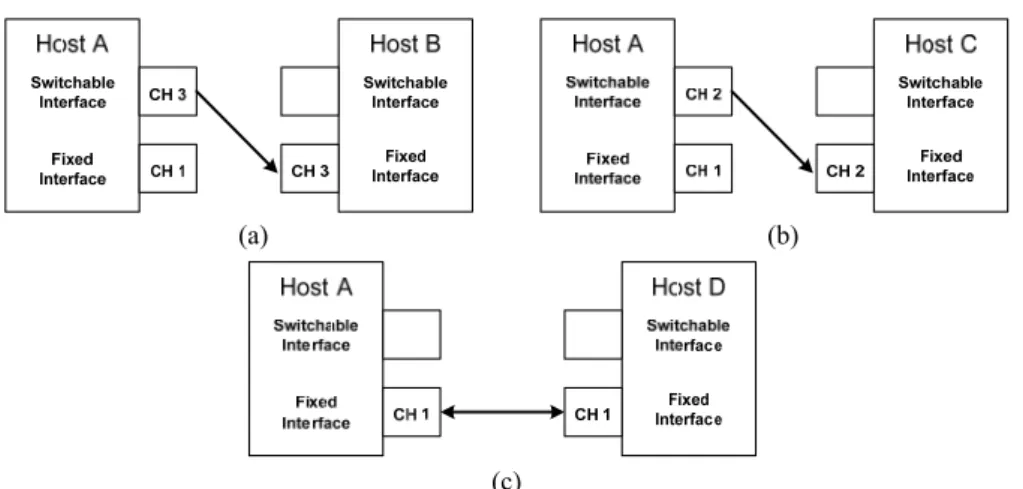
Because the channels assigned on fixed interfaces are unchanged and known by other nodes, the communication overhead used to negotiate a common channel is no longer required before any transmission. Furthermore, each node collects the information of its neighbors’ fixed channels from broadcast messages, so this scheme does not re-quire a separate control channel or the time synchronization scheme. Fig. 2 illustrates the possible communication scenarios. Assume the fixed channel of host A is assigned channel 1. If A wants to communicate with the host B (C), then A would switch its
(a) (b)
(c)
Fig. 2. The possible communication scenarios.
switchable interface to channel 3 (2) to communicate with B’s (C’s) fixed interface (see Figs. 2 (a) and (b)). If other hosts, e.g., D, are assigned the same fixed channel 1 as A, A would use its fixed interface to communicate with their fixed interfaces (Fig. 2 (c)).
In order to reduce the overhead of interface switching delay, the protocol equips each host with as many queues as channels. Each queue is associated to a channel and the packets in the queue will be transmitted on this channel. The scheme puts a packet into the associated queue according to the receiver’s fixed channel. Therefore, each host can choose a channel for its switchable interface based on the condition of queues. That is, the switchable interface does not change its channel per packet. This method can reduce the interface switching delay by forcing each switchable interface to stay on the assigned channel for a period of time to transmit packets.
The staying period of a switchable interface on each switchable channel must be carefully defined. A small period increases switching overhead, while a too long period may cause starvation of other switchable channels and results in more end-to-end delay. A switchable interface can only stay on each channel for a given duration at most and is always switched to the channel with the oldest queued packets. It is switched to a new channel only when the queues of other switchable channels are not empty and one of the following conditions holds:
1. The queue of the current switchable channel is empty.
2. The switchable interface has been on the current channel for more than the given du-ration.
Each host has a virtual network allocation vector (NAV) for each channel. When a host switches its interface to a new channel, its NAV for this channel may not be correct because of the multi-channel hidden terminal problem. In order to avoid this problem, each host must be idle for a time interval, denoted as WaitingTime, to update its NAV. The length of WaitingTime is defined as the transmission time of one maximum size packet.
There are two drawbacks of this protocol. First, the duration on each channel is fixed, but the traffic load destined for each host is usually different and varies with time.
Second, WaitingTime is too long so as to decrease the utilization of switchable interfaces. In this paper, the proposed protocol is based on this hybrid channel assignment approach and introduces two methods to solve the above two problems.
3. THE PROPOSED MAC PROTOCOL: HMCMP
The proposed MAC protocol is called as Hybrid Multi-Channel MAC Protocol (HMCMP). This is an improvement of the MAC protocol of HMCP [14]. A dynamic channel duration assignment strategy is designed. It can adjust the channel duration ac-cording to the traffic load of each channel. Besides, a dynamic waiting time assignment strategy is presented to improve the utilization of interfaces.
3.1 Dynamic Channel Duration Time Assignment
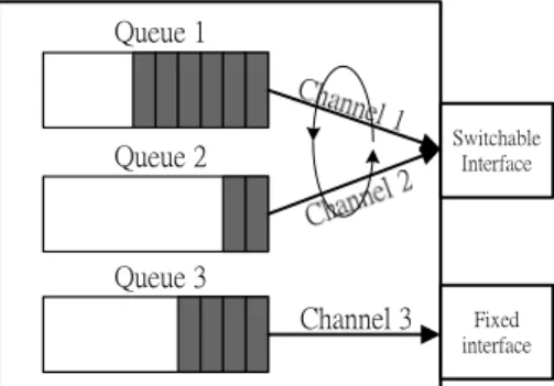
Consider a host with two interfaces, fixed and switchable interfaces, as shown in Fig. 3. Channels 1 and 2 are assigned to the switchable interface and channel 3 is assigned to the fixed interface. The operation of switchable interface is illustrated in Fig. 4. The switchable interface uses channels 1 and 2 interchangeably. That is, in the beginning, the switchable interface switches its channel to channel 1, waits for a period of time WT1, and then transmits the packets in queue 1 for a period of time TT1. Next, the switchable interface switches its channel to channel 2, waits a period of WT2 time, and transmits the packets in queue 2 for a period of time TT2 time. Note that the sum of waiting time WTi
Switchable Interface Fixed interface Queue 2 Queue 3 Channel 3 Queue 1
Fig. 3. A host with fixed and switchable interfaces.
and data transmission time TTi is the duration of switchable interface staying on channel
i in a switching cycle, denoted as DSi. The more the number of packets a queue has, the
more transmission time it requires. Thus, each host has to determine the duration period DSi for each switchable channel i dynamically.
The hybrid scheme allows switchable interfaces to switch among diverse channels. However, due to the switching delay of devices, the utilization of interfaces would be deteriorated as the switching is frequent. For this reason, we further divide the duration of each channel into two periods (see Fig. 4). The first is called the Fixed Staying Time (FST). For each channel, if there are some packets for transmission on that channel, we should restrict the host to transmit on the channel for at least an FST period. The main purpose is to avoid frequent switching that would shorten the real transmission time. Note that the FST should be taken as a constant no less than the switching delay depend-ing on devices. The second period is called the Dynamic staydepend-ing Time (DST). It allows the utilization of each channel i to be in proportion to the number of packets in the asso-ciated queue i. The DSTi of switchable channel i is defined as:
i i X DST M C = × ( 1 ) where Xi is the number of packets in the associated queue i at the beginning of each cycle, C is the total capacity of all queues of switchable channels and M is the maximum of the
sum of DSTs in a switching cycle. M can be set as the time that is required to transmit C packets. For example, as shown in Fig. 3, we assume the size of each queue is 50 packets,
M is 10 ms, the queue length of channel 1 is 30 and channel 2 is 10. Then,
1 30 10 ms 3 ms, 50 2 DST = × = × 2 10 10 ms 1 ms. 50 2 DST = × = ×
Note that there is no starvation or farness problem, since in each cycle M, the dura-tion of each channel is in pordura-tion to the number of packets enqueued on it. Besides, for simplicity we assume the packet sizes are equal here. For more general situations, we can apply the same rule except that Xi is now indicated the total size of packets enqueued on
channel i. In addition, the DTSi’s will be recalculated at the end of each switching cycle. 3.2 Dynamic Waiting Time Assignment
As shown in Fig. 1, after the end of communication between C and D, C might ini-tiate communication with B and send an RTS packet on channel 1. It will cause a colli-sion between hosts C and B. In order to solve this multi-channel hidden terminal problem, when the switchable interface switches to a new channel, it has to idle for a period of time, called the waiting time, before it can transmit data. Note that the length of the waiting time can be set to be the transmission time of one maximum size packet. How-ever, in this case the waiting is too large to sacrifice the utilization of switchable inter-faces. Nonetheless, shorter waiting time may cause collisions. Thus, we try to find a
value of waiting time which is the equilibrium of interface utilization and collision oc-currence. However, how to set the value of waiting time depends on the probability of collision occurrence. If the probability of collision occurrence for a switchable interface on some channel is low, a shorter value of the waiting time for this channel in this inter-face is suitable. On the contrary, it would need longer waiting time to avoid the high probability of collision occurrence.
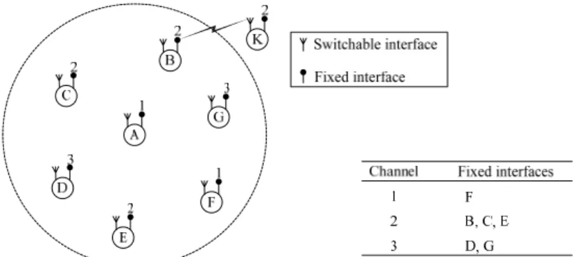
Consider an example as shown in Fig. 5. Hosts B, C, D, E, F, and G are in the transmission range of host A. When host A switches to channel 2 in which host B is re-ceiving data from host K, a collision occurs. Thus, the collision probability of the chan-nel that switchable interface switches to, depends on the number of its neighbors’ fixed interfaces using that channel. For example, consider host A (see Fig. 5). The fixed inter-face of host F is set to channel 1, hosts B, C, E are set to channel 2, and hosts D, G are set to channel 3. If host A switches its switchable interface to channel 2, it has more colli-sion probability than switching to channel 1. This is because there are three neighbors of host A using channel 2 for their fixed interfaces and only one neighbor using channel 1 for its fixed interface. We assign longer waiting time WTi for channel i to reduce the probability of collision if the number of its neighbors’ fixed interfaces using channel i is large.
Fig. 5. The neighbor’s interfaces of host A fixed on channels 1, 2 and 3.
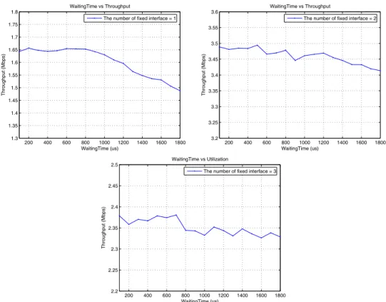
We use simulations to determine suitable values of WTi for various numbers of neighbors’ fixed interfaces. Fig. 6 is the aggregate throughput of various waiting time WTi for one, two and three neighbors’ fixed interfaces on channel i.
We summarize the waiting time with the highest aggregate throughputs in Table 1. We adopt these values in our proposed protocol to set the waiting time. Moreover, we can know that the length of waiting time has the worse performance from Fig. 6.
Table 1. The suite of the best WaitingTime.
The number of neighbor’s fixed interfaces WaitingTime(us)
1 200 2 500 3 700
200 400 600 800 1000 1200 1400 1600 1800 1.3 1.35 1.4 1.45 1.5 1.55 1.6 1.65 1.7 1.75 1.8 WaitingTime (us) Throughput (Mbps) WaitingTime vs Throughput
The number of fixed interface = 1
200 400 600 800 1000 1200 1400 1600 1800 3.2 3.25 3.3 3.35 3.4 3.45 3.5 3.55 3.6 WaitingTime (us) Throughput (Mbps) WaitingTime vs Throughput
The number of fixed interface = 2
200 400 600 800 1000 1200 1400 1600 1800 2.2 2.25 2.3 2.35 2.4 2.45 2.5 WaitingTime (us) Throughput (Mbps) WaitingTime vs Utilization
The number of fixed interface = 3
Fig. 6. The aggregate throughput of various waiting times when the number of neighbors’ fixed interfaces is one, two and three.
4. SIMULATION RESULTS
In this section, we compare the performance of the proposed MAC protocol with that of HMCP [14] and IEEE 802.11 MAC protocol in ns-2 [17]. The duration of each simulation is 120 seconds. The basic rate is 1 Mbps and the data rate is 11 Mbps. All nodes are assumed to be stationary and their transmission ranges are 250m. The packet size is fixed at 1,024 bytes. The number of channels is three and the interface switching delay is assumed to be 1ms. The FST and the maximum value of sum of DSTs in a switching cycle M are assigned 4ms and 10ms, respectively. These two values are chosen by the experiment and the performance of using these two values is good. We only con-sider the Constant Bit Rate (CBR) traffic and make the packet arrival rate varied to simu-late the various offered loads.
4.1 Chain Topology
We discuss a chain topology first. There are six nodes in a chain and the neighbors are away from each other at a distance of 200m. The aim of this experiment is to study the aggregate throughput and the average end-to-end delay in a multi-hop network. There are two traffic flows applied to this topology. One flow is from nodes 1 to 6 and the other
is in the reverse direction. The fixed interfaces from node 1 to node 6 are assigned chan-nels 1, 2, 3, 1, 2, 3, respectively. This kind of traffic can produce much of the occurrence of multi-channel hidden terminal problem and the unbalanced loads of each channel.
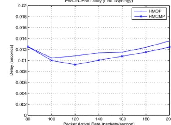
Figs. 7 and 8 show, respectively, the aggregate throughput and the average end-to- end delay. We can see from Fig. 7 that the hybrid MAC protocols utilizing multiple channels efficiently can improve the original IEEE 802.11 MAC protocol greatly. Be-sides, our proposed method can further increase the throughput specially when the pack-ets arrival rate goes large. On the other hand, the average end-to-end delay of IEEE 802.11 MAC protocol is much larger than that of the hybrid MAC protocols, so we do not compare it in the Fig. 8. The performances of the aggregate throughput and the aver-age delay in HMCMP outperform that in HMCP by more than 10 percents under heavy load. This is because the proposed dynamic DSTi assignment can adapt the transmission
time to the traffic loads and the proposed dynamic waiting time assignment can improve the utilization of interfaces.
0 50 100 150 200 0 0.2 0.4 0.6 0.8 1 1.2 1.4 1.6 1.8 2
Packet Arrival Rate (packets/second)
Throughput (Mbps)
Throughput (Line Topology) HMCP HMCMP IEEE802.11 80 100 120 140 160 180 200 0 0.002 0.004 0.006 0.008 0.01 0.012 0.014 0.016 0.018 0.02
Packet Arrival Rate (packets/second)
Delay (seconds)
End−to−End Delay (Line Topology) HMCP HMCMP
Fig. 7. The aggregate throughput of a chain topology.
Fig. 8. The average end-to-end delay of a chain topology.
4.2 Grid topology
In this section, we study the performance of the protocols in a multi-hop ad-hoc network. There are three sizes of grids, respectively a 3 × 3 grid, a 6 × 6 grid and a 9 × 9 grid. The distance between adjacent nodes is 150m. The traffic flows are originated and received by nodes on the margin of the grid. The directional of any flow can be either vertical or horizontal. Fig. 9 illustrates the traffic flows on the 6 × 6 grid.
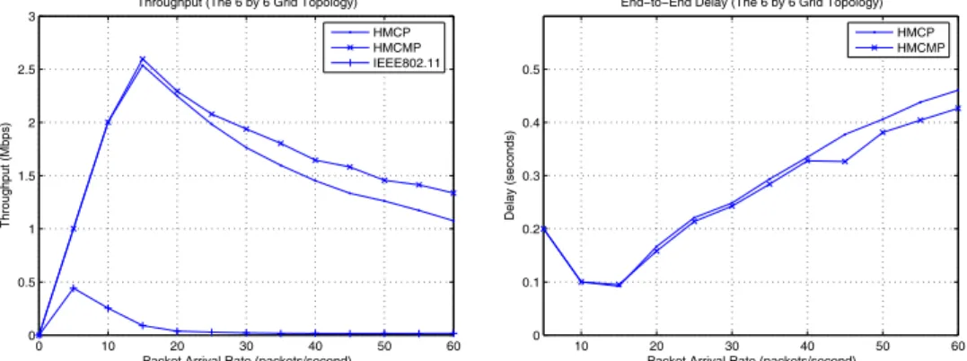
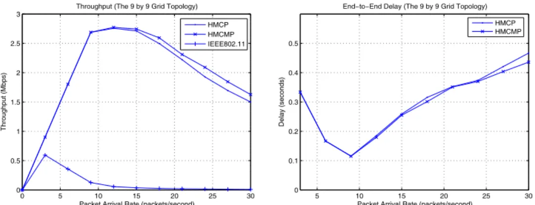
Figs. 10, 11, and 12 show the aggregate throughput and the average end-to-end delay for grids 3 × 3, 6 × 6 and 9 × 9, respectively. The results show that the hybrid pro-tocols still have good performances over the IEEE 802.11 MAC protocol. For hybrid protocols, the performances in HMCMP also outperform that in HMCP, but the im-provement of grid topology is not as great as that of the chain topology, especially for the topology of 9 × 9. With the increasing grid size, the improvement of the proposed proto-col is small.
Fixed channel: CH 2 Fixed channel: CH 3 Fixed channel: CH 1
Fig. 9. The traffic flows for the 6 × 6 grid.
0 20 40 60 80 100 120 0 0.5 1 1.5 2 2.5 3 3.5 4 4.5 5 5.5
Packet Arrival Rate (packets/second)
Throughput (Mbps)
Throughput (The 3 by 3 Grid Topology) HMCP HMCMP IEEE802.11 40 50 60 70 80 90 100 110 120 0 0.005 0.01 0.015 0.02 0.025 0.03 0.035 0.04 0.045 0.05
Packet Arrival Rate (packets/second)
Delay (seconds)
End−to−End Delay (The 3 by 3 Grid Topology) HMCP HMCMP
Fig. 10. The aggregate throughput and the average end-to-end delay of a 3 × 3 grid topology.
0 10 20 30 40 50 60 0 0.5 1 1.5 2 2.5 3
Packet Arrival Rate (packets/second)
Throughput (Mbps)
Throughput (The 6 by 6 Grid Topology) HMCP HMCMP IEEE802.11 10 20 30 40 50 60 0 0.1 0.2 0.3 0.4 0.5
Packet Arrival Rate (packets/second)
Delay (seconds)
End−to−End Delay (The 6 by 6 Grid Topology) HMCP HMCMP
Fig. 11. The aggregate throughput and the average end-to-end delay of a 6 × 6 grid topology.
5. CONCLUSION
In this paper, we propose a new multi-channel MAC protocol HMCMP to improve the unbalanced allocation of resources and the utilization of both channels and interfaces in HMCP. We use a dynamic DST assignment scheme to dynamically adapt the trans-mission time to the varied traffic loads and a dynamic waiting time assignment scheme to improve the utilization of interfaces. We have compared the performance of the proposed
0 5 10 15 20 25 30 0 0.5 1 1.5 2 2.5 3
Packet Arrival Rate (packets/second)
Throughput (Mbps)
Throughput (The 9 by 9 Grid Topology) HMCP HMCMP IEEE802.11 5 10 15 20 25 30 0 0.1 0.2 0.3 0.4 0.5
Packet Arrival Rate (packets/second)
Delay (seconds)
End−to−End Delay (The 9 by 9 Grid Topology) HMCP HMCMP
Fig. 12. The aggregate throughput and the average end-to-end delay of a 9 × 9 grid topology.
protocol with that of HMCP and IEEE 802.11 MAC protocol. The results show that our improvements work well and the hybrid MAC protocols with utilizing multiple channels efficiently have better performances over IEEE 802.11 MAC protocol. For the further research, it is interesting to design more sophisticated rules to determine any dynamic periods. For instance, the WT would not only be a function of the number of interfaces, but also a function of the arrival rate and frame size.
REFERENCES
1. A. Tzamaloukas and J. J. G. L. Aceves, “A receiver-initiated collision-avoidance protocol for multi-channel networks,” in Proceedings of IEEE INFOCOM, Vol. 1, 2001, pp. 22-26.
2. J. So and N. H. Vaidya, “Multi-channel MAC for ad hoc networks: handling multi-channel hidden terminals using a single transceiver,” in Proceedings of the 5th
ACM International Symposium on Mobile Ad Hoc Networking and Computing, 2004,
pp. 222-233.
3. N. Choi, Y. Seok, and Y. Choi, “Multi-channel MAC protocol for mobile ad hoc networks,” in Proceedings of IEEE Vehicular Technology Conference, Vol. 2, 2003, pp. 1379-1382.
4. P. Bahl, R. Chandra, and J. Dunagan, “SSCH: slotted seeded channel hopping for ca- pacity improvement in IEEE 802.11 ad-hoc wireless networks,” in Proceedings of
the 10th Annual International Conference on Mobile Computing and Networking,
2004, pp. 216-230.
5. C. Y. Chang, H. C. Sun, and C. C. Hsieh, “MCDA: an efficient multi-channel MAC protocol for 802.11 wireless LAN with directional antenna,” in Proceedings of IEEE
International Workshop on Information Networking and Applications, Vol. 2, 2005,
pp. 64-67.
6. P. Bahl, A. Adya, J. Padhye, and A. Wolman, “Reconsidering wireless systems with multiple radios,” ACM SIGCOMM Computing Communication Review, Vol. 34, 2004, pp. 39-46.
multihop wireless networks,” in Proceedings of IEEE Wireless Communication and
Networking Conference, Vol. 3, 1999, pp. 1402-1406.
8. A. Nasipuri and S. R. Das, ”Multichannel CSMA with signal power-based channel selection for multihop wireless networks,” in Proceedings of IEEE Vehicular
Tech-nology Conference, Vol. 1, 2000, pp. 211-218.
9. N. Jain, S. R. Das, and A. Nasipuri, “A multichannel CSMA MAC protocol with re-ceiver-based channel selection for multihop wireless networks,” in Proceedings of
the 9th International Conference on Computer Communications and Networks, 2001,
pp. 432-439.
10. S. L. Wu, C. Y. Lin, Y. C. Tseng, and J. P. Sheu, “A new multi-channel MAC pro-tocol with on-demand channel assignment for multi-hop mobile ad hoc networks,” in
Proceedings of International Symposium on Parallel Architectures, Algorithms and Networks, 2000, pp. 232-237.
11. Y. C. Tseng, S. L. Wu, C. Y. Lin, and J. P. Sheu, “A multi-channel MAC protocol with power control for multi-hop mobile ad hoc networks,” in Proceedings of
Inter-national Conference on Distributed Computing Systems Workshop, 2001, pp. 419-
424.
12. H. Koubaa, “Fairness-enhanced multiple control channels MAC for ad hoc net-works,” in Proceedings of IEEE Vehicular Technology Conference, Vol. 3, 2005, pp. 1504-1508.
13. J. S. Pathmasuntharam, A. Das, and A. K. Gupta, “Primary channel assignment based MAC (PCAM) − a multi-channel MAC protocol for multi-hop wireless net-works,” in Proceedings of IEEE Wireless Communications and Networking
Confer-ence, Vol. 2, 2004, pp. 1110-1115.
14. K Pradeep and N. H. Vaidya, “Routing and link-layer protocols for multi-channel multi-interface ad hoc wireless networks,” ACM SIGMOBILE Mobile Computing
and Communications Review, Vol. 10, 2006, pp. 31-43.
15. J. Mo, H. S. W. So, and J. Walrand, “Comparison of multi-channel MAC protocols,” in Proceedings of ACM International Symposium on Modeling, Analysis and
Simula-tion of Wireless and Mobile Systems, 2005, pp. 209-218.
16. A. Raniwala, K. Gopalan, and T. Chiueh, “Centralized channel assignment and rout-ing algorithms for multi-channel wireless mesh networks,” ACM SIGMOBILE
Mo-bile Computing and Communication Review, Vol. 8, 2004, pp. 50-65.
17. ns-2, http://www.isi.edu/nsnam/ns/.
Chi-Yu Li (李奇育) received the B.S. degree in Computer
and Information Science from National Chiao Tung University, Taiwan, in 2004 and M.S. degree in Computer and Information Science from National Chiao Tung University, Taiwan, in 2006. His research interests include WMN (wireless mesh network) and wireless MAC protocols.
An-Kai Jeng (鄭安凱) received the B.S. in Statistics from Tamkang University and the M.S. in Management Information System from National Chi Nan University in 2001 and 2003, re-spectively. He is currently pursuing the Ph.D. degree in the De-partment of Computer and Information Science at National Chiao Tung University, Taiwan, R.O.C. His research interests include wireless networks, algorithm design and analysis, scheduling theory and operation research.
Rong-Hong Jan (簡榮宏) received the B.S. and M.S.
de-grees in Industrial Engineering, and the Ph.D. degree in Computer Science from National Tsing Hua University, Taiwan, in 1979, 1983, and 1987, respectively. He joined the Department of Com-puter and Information Science, National Chiao Tung University, in 1987, where he is currently a Professor. During 1991-1992, he was a Visiting Associate Professor in the Department of Com-puter Science, University of Maryland, College Park, MD. His research interests include wireless networks, mobile computing, distributed systems, network reliability, and operations research.