A Dynamic Scaling FFT Processor
for DVB-T Applications
Yu-Wei Lin, Hsuan-Yu Liu, and Chen-Yi Lee
Abstract—This paper presents an 8192-point FFT processor for DVB-T systems, in which a three-step radix-8 FFT algorithm, a new dynamic scaling approach, and a novel matrix prefetch buffer are exploited. About 64 K bit memory space can be saved in the 8 K point FFT by the proposed dynamic scaling approach. More-over, with data scheduling and pre-fetched buffering, single-port memory can be adopted without degrading throughput rate. A test chip for 8 K mode DVB-T system has been designed and fabricated using 0.18- m single-poly six-metal CMOS process with core area of 4.84 mm2. Power dissipation is about 25.2 mW at 20 MHz.
Index Terms—DVB-T, fast Fourier transform (FFT), orthogonal frequency division multiplexing (OFDM).
I. INTRODUCTION
F
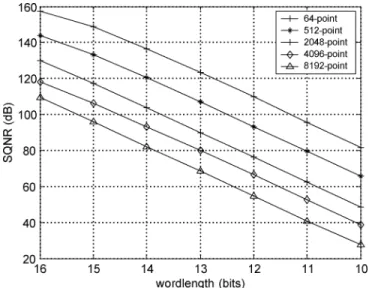
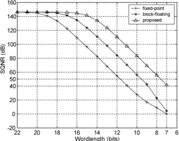
AST FOURIER TRANSFORM (FFT) and inverse fastFourier transform (IFFT) are the key computational blocks in orthogonal frequency division multiplexing (OFDM) system. The long-size FFT is commonly adopted in OFDM system to increase transmission bandwidth or transmission efficiency, such as DVB-T (Digital Video Broadcasting—Terrestrial) [1], DAB (Digital Audio Broadcasting), VDSL (Very-high-speed Digital Subscriber Line), and other mobile applications. In order to increase transmission bandwidth or to increase transmis-sion efficiency, a long-size FFT processor is needed in OFDM system. Today, there has been a lot of research work reported on short-size FFT processors, but there has been few on long-size FFT processors. On designing a long-size FFT processor except for considering its specs, one still has to consider its power consumption and hardware cost. The power dissipation of both data access in memory and operation of complex multipliers is more than 75% of total power consumption in an FFT processor [2]. The prefetch buffer based FFT processor with higher radix algorithm is suitable for long-size FFT because it reduces lots of data accesses and complex multiplications [3], [4]. But a suitable prefetch buffer scheme to ensure that multiple data can be read or written simultaneously and an efficient approach to implement higher radix algorithm with less hardware cost are needed. Fig. 1 shows the signal-to-quantization-noise ratio (SQNR) of different-size FFT in different wordlength. It can be clearly seen that more wordlength is needed to maintain the same SQNR in long-size FFT. The memory occupies lots of chip area and power consumption especially in long-size Manuscript received March 10, 2004; revised June 7, 2004. This work was supported by the National Science Council of Taiwan, R.O.C., under Grant NSC902215-E-009-105, and by the Ministry of Economic Affairs, R.O.C., under Grant 92-EC-17-A-03-S1-0005.
The authors are with the Department of Electronics Engineering, National Chiao University, Hsinchu 300, Taiwan, R.O.C. (e-mail: ywlin@si2lab.org).
Digital Object Identifier 10.1109/JSSC.2004.835815
Fig. 1. SQNR of different-size FFT in different wordlengths.
FFT. The occupied area of the memory module is not only proportional to the number of stored data and wordlength but also proportional to the number of ports. Single-port memory is used by Wu et al. in FFT processors to reduce area significantly [5]. Unfortunately, its throughput becomes degraded due to stall operations in data access. Dynamic scaling approach can be used to increase SQNR and to reduce the wordlength in FFT processors [6]. In this paper, both a dynamic scaling approach and single-port memory structure will be exploited to reduce memory requirements without any throughout degradation. In addition, a novel three-level hierarchy memory with matrix prefetch buffer scheme and an efficient approach to implement radix-8 FFT will also be proposed to reduce power consump-tion.
II. ALGORITHM
The -point Discrete Fourier Transform (DFT) of a sequence is defined as
(1) where and are complex numbers. The twiddle factor is
(2) In (1), the computational complexity is through directly performing the required computation. By using the FFT algorithm, the computational complexity can be reduced to , where means the radix- FFT. The radix- FFT 0018-9200/04$20.00 © 2004 IEEE
(3) Using (3), (1) can be rewritten as
(4)
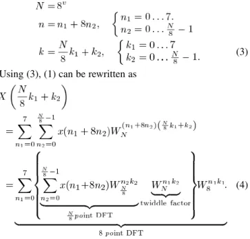
Eq. (4) can be considered as a two-dimensional DFT. One is /8-point DFT and the other is 8-point DFT, as shown in Fig. 2. Then, by decomposing the /8-point DFT into the 8-point DFT recursively through times, where is equal to , we can complete the -point radix-8 DIT FFT algorithm. In (4), an 8-point DFT, which is a basic operation unit, is called the butterfly, as shown in Fig. 3. A butterfly is also an essential arithmetic component, which is called a butterfly unit (BU) in an FFT processor, in hardware implementation. In Fig. 3, it is clearly seen that seven complex multipliers (28 real multipliers) are needed in a BU by directly mapping approach to implement 8-point DFT. Thus, radix-8 FFT algorithm is seldom used in single-memory FFT architecture, because the hardware cost of its BU is too high to implement. In order to implement radix-8 FFT algorithm more efficiently, following the radix- DIF FFT algorithm proposed by He and Torkelson [7] we further decom-pose butterfly of radix-8 DIT FFT algorithm into three steps and apply the radix-2 index map to the radix-8 butterfly.
Eq. (4) can also be written as
(5) where
(6)
Fig. 2. Signal flow graph (SFG) of radix-8 FFT algorithm.
Fig. 3. Butterfly of radix-8 FFT.
Applying a three-dimensional linear index map, and can be defined as
(7) By means of (7), (5) has the following form:
(8) The twiddle factor in (8) is
Fig. 4. Butterfly of three-step radix-8 FFT.
Using (9), (8) becomes the equation shown at the bottom of the page, where
(11) In (10), we use the radix-2 index map to divide the 8-point DFT into three steps. Fig. 4 shows the butterfly of the three-step DIT radix-8 FFT. The twiddle factors, and , at the third step are trivial complex multiplications, because they
can be written as and ,
respec-tively. Thus, a complex multiplication with one of the two co-efficients can be computed using additions and a real multipli-cation, whose hardware can be realized by six shifters and four
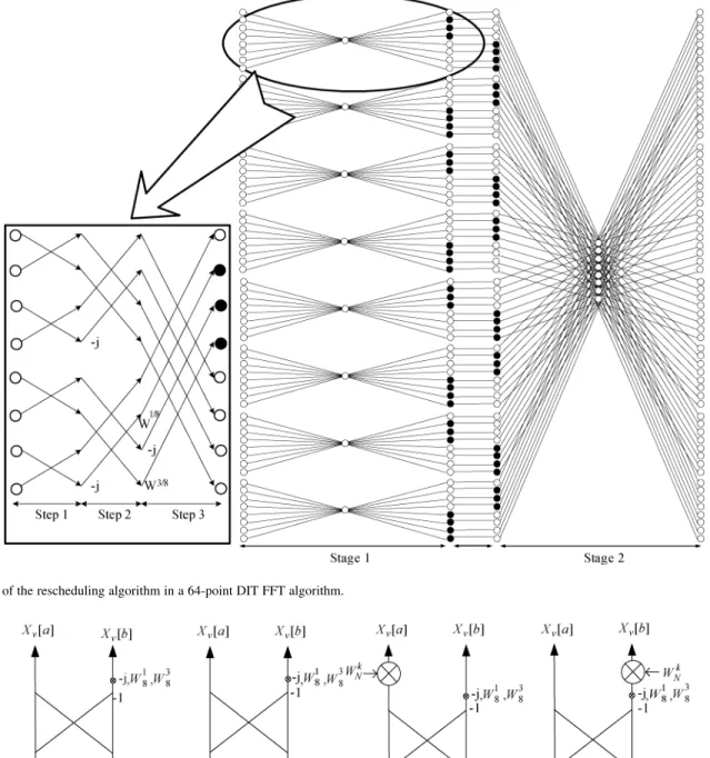
Fig. 5. Scheduling of the complex multiplications: (a) before scheduling, (b) and (c) after scheduling.
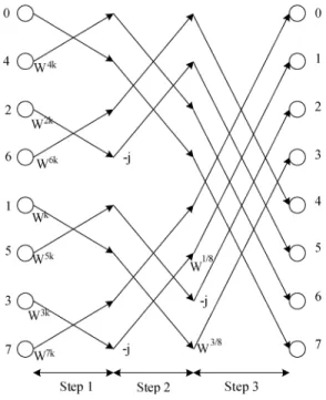
adders [8]. The butterfly of the three-step DIT radix-8 FFT al-gorithm is similar to the 8-point radix-2 FFT alal-gorithm. But the number of complex multiplications used in the former algorithm is only 7/12 of that used in the latter algorithm. All the complex multiplications are performed in the first time slot in three-step DIT radix-8 FFT algorithm, as shown in Fig. 5(a), which is the scheduling of complex multiplication in three-step radix-8 FFT. In Fig. 5(a), T1, T2, and T3 mean the time slot of each step in the butterfly of three-step radix-8 FFT algorithm and the rec-tangle means complex multiplications in each time slot. In order to balance complex multiplications in three time slots in the but-terfly and to minimize the number of complex multipliers, we propose a rescheduling method in three-step radix-8 FFT algo-rithm. Take an example for radix-8 DIT FFT. In the traditional radix-8 FFT, there are two stages , each stage contains eight butterflies ( ), and all twiddle factors are at the second stage. Now we can move some twiddle factors from the second stage to the first stage, as shown in Fig. 6. The black
Fig. 6. SFG of the rescheduling algorithm in a 64-point DIT FFT algorithm.
Fig. 7. Operation modes of the BU in rescheduling approach.
point in Fig. 6 means to multiply the twiddle factor at that point. In the three-step radix-8 FFT, each butterfly is divided into three steps, as shown in Fig. 4 and all removed twiddle factors are at the third step. Thus, there are at most four complex multiplica-tions in each time slot of the butterfly and only four complex multipliers are needed in the three-step radix-8 butterfly after rescheduling. Fig. 5(b) and (c) shows the scheduling of the com-plex multiplication after rescheduling.
Some operation modes need to be added in Fig. 7 since the twiddle factors are located at both the first and the third steps of the butterfly under the rescheduling approach. The operation modes, modes A and B, are operated at the first step of the but-terfly, and the other two operation modes, modes C and D, are at
the third step of the butterfly. In order to let eight data in the pro-cessor operate in the same mode at each step of the butterfly to reduce operation complexity, we propose a rescheduling algo-rithm for -point FFT as below. We then define the following.
• The stage of -point FFT is from 1 to .
• The group number in the th stage is from 0 to . • The butterfly number of each group in the th stage is from
0 to .
• BU_1 is the operation mode in the first step of the butterfly. • BU_3 is the operation mode in the third step of the
but-terfly.
Fig. 8. Rescheduling algorithm.
A. Dynamic Scaling Approach
In order to maintain data accuracy in fixed-point FFT, the in-ternal wordlength of the FFT processor is usually larger than the wordlength of input data to achieve a higher SQNR, especially in a long-size FFT processor. The block-floating point (BFP), which is one of the dynamic scaling approaches, is usually used in FFT processors to minimize the quantization error. In the tra-ditional BFP, the largest value is detected and all computational results are scaled by a scale factor in stage before starting the calculations of the stage [6].
1) Proposed Approach: A new BFP approach, which can be implemented by a prefetch buffer based FFT processor, is proposed. It improves SQNR dramatically by increasing the number of the scale factor and block in the FFT algorithm. Fig. 9 shows an example for the block size having four points in 16-point FFT. The scale factor is determined when the oper-ation of each block is finished. The data in the block are scaled before starting to operate the next block. All scale factors need to be stored in a table and used when data are operated.
2) Simulation: Signal processing quality of the three data representations, including fixed point, traditional block-floating point, and the proposed approach is simulated. Because SQNR
Fig. 9. Proposed block-floating point approach.
Fig. 10. SQNR for 8 K point FFT with different data representations.
is highly dependent on input data, we build up a system plat-form for 8 K mode DVB-T system and all data are generated by this platform. The block size of our approach is 64 points. It is clearly seen that our proposed approach can minimize quantiza-tion error efficiently and provide much higher SQNR than the others at the same bit rate, as shown in Fig. 10.
The performance of our proposed dynamic scaling FFT algorithm approach is evaluated with an 8 K mode DVB-T system based on different conditions. We consider the case of 16 QAM and 64 QAM with code rate 7/8 and 2/3 in AWGN channel. Bit error rate (BER) plotted against carrier-to-noise ratio (CNR) is shown in Fig. 11. Because higher SQNR can be provided in our approach, less wordlength is needed in an FFT processor. Through the complete DVB-T system simulation,
Fig. 11. Performance of 8 K mode DVB-T system after Viterbi decoding in AWGN channel.
the wordlength of the real and imaginary parts has about 4 bits less than that of the fixed-point when BER meets the 8 K mode DVB-T standard. So about 64 K ( K , for both real and imaginary parts) bits of memory capacity can be saved by this approach.
III. ARCHITECTURE
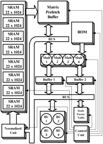
For designing a low-power FFT processor, it is important to minimize memory access, which dominates the power con-sumption in FFT processors. The three-level memory architec-ture is proposed in our FFT processor to increase energy effi-ciency. A block diagram of the proposed FFT architecture is shown in Fig. 12. The first level is main memory which is di-vided into eight banks to allow concurrent accesses of multiple data and its size is 8 K points. The matrix prefetch buffer with 64 points, which is the second level, is designed for radix-8 FFT algorithm. The third level is the buffer, consisting of buffer 1 and buffer 2, each of which is 8 points. Through an appropriate scheduling among three-level memories, single-port memory can be used in the first and second level without any throughput rate degradation. Besides, the wordlength can be minimized by using our proposed dynamic scaling approach.
The BU is the kernel of the arithmetic unit in an FFT pro-cessor, as shown in Fig. 12. It includes a complex multiplier, a trivial multiplier dealing with , , , a complex adder/subtractor, and multiplexers. ROM is used to store twiddle factors. Only 1/8 period of cosine and sine waveforms are stored in ROM and the other period waveforms can be reconstructed by these stored values. Data are multiplied by the twiddle factors, when they are read from or written into the buffers. The data in buffers need three cycles in BUs to implement the three-step radix-8 FFT algorithm. The scale factor table is to store the scale factor of each block. The number of block number is 128 in our proposed 8 K point FFT architecture. Each scale factor has 4 bits. So the size of the scale factor table is 4 128 bits. The function of the normalized unit is used to scale the data before they are stored in memory. The memory space increased by using the scale factor table
Fig. 12. Block diagram of the proposed FFT architecture.
and normalized unit is much less than that saved by using the proposed dynamic scaling approach.
A. Matrix Prefetch Buffer
The architecture of the prefetch buffer depends on the FFT algorithm. In order to ensure that lots of data in the prefetch buffer can be read or written simultaneously, higher banked memory in the prefetch buffer architecture is needed in higher-radix FFT algorithm. As well, two prefetch buffers are needed in the FFT processor to avoid stall in the BUs. While one is op-erating with BU, the other is exchanging data with memory and vice versa [3]. Using both three-step radix-8 FFT algorithm and data scheduling method, only one prefetch buffer is needed in our design.
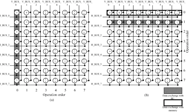
The proposed matrix prefetch buffer scheme is shown in Fig. 13. Columns 0 7 are eight butterflies of the first stage and rows 0 7 are eight butterflies of the second stage, as shown in Fig. 6. Eight data in the matrix prefetch buffer are read or written simultaneously in the horizontal or vertical direction each time.
When data have been completely loaded from memory in order, the FFT processor starts to implement 64 points FFT with three-step radix-8 FFT algorithm. At the first stage, data are loaded into buffers in the direction of column in order, as pre-sented in Fig. 13(a). All computed data are restored to the same addresses in the matrix prefetch buffer. At the second stage, data are loaded into the buffers in the row direction. After data are operated in buffers, they will wait for scaling in the normalized
Fig. 13. (a) Operation of the matrix prefetch buffer at the first stage. (b) Operation of the matrix prefetch buffer at the second stage.
Fig. 14. Scheduling of the data in the matrix prefetch buffer operated with BUs and exchanged with memory. unit. When the data of row 0 have been loaded into the
normal-ized unit, new data will be loaded into row 0 from the memory, as shown in Fig. 13(b). In the next 64-point, the direction of the first stage will change to row direction because the direction of the updated data is in row direction.
B. Memory Capacity
The main memory occupies large chip area in the long-size FFT processor. The total memory size in our design is up to
176 K bit, consisting of 11-bit real and imaginary parts. Fig. 14 shows scheduling of the data in the buffers operated with BU and exchanged with prefetch buffer if single-port memory is adopted. In this figure, the white rectangle is the operational time of the data in buffers. The gray rectangle is the time spent in exchanging the data in the matrix prefetch buffer or loaded into the normalized unit. It can be clearly seen that there is no stall in this scheduling. Similarly, data are loaded from the first level into the second level at the second stage of 64-point FFT and they are restored to the first level from the normalized unit
Fig. 15. Microphoto of the proposed FFT processor.
TABLE I
CHIPSUMMERY INOURPROPOSEDFFT PROCESSOR
at the first stage of 64-point FFT. Thus, the single-port memory can be used without degrading throughput rate.
IV. CHIPIMPLEMENTATION
Before VLSI implementation, we build up a MATLAB model which includes our proposed three-step radix-8 FFT with rescheduling algorithm, dynamic scaling approach, and matrix prefetch buffer scheme to verify our algorithm, and we figure out that the optimal bit number for data representation is 11 bits in our FFT processor according to the whole DVB-T system simulation.
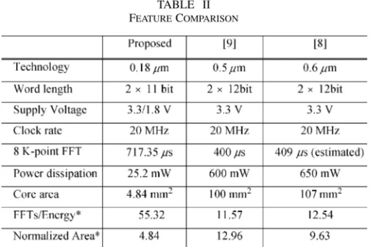
This 8 K point FFT test chip is fabricated in 0.18- m one-poly six-metal CMOS process. The core size is 2.26 mm 2.26 mm. The chip microphoto is shown in Fig. 15. The 92-pin chip is packaged in 128-pin CQFP package, where 40 pins are power pin and 52 pins are signal pin. Table I lists the chip summary and some measurement results. It completes the 8 K point FFT in 717.35 s with power dissipation of 25.2 mW at 20 MHz which meets DVB-T standard (i.e., 896 s in 8 K mode). Table II shows a summary of the features of three 8 K point FFT processors. The normalized indexes for power consumption and chip area,
FFTs per energy and normalized area, are defined respectively by the following relations [3]:
(12) (13) where FFTs per energy are the number of 8 K complex FFTs calculated per unit of energy normalized to 0.18- m technology, and the normalized area is the chip area normalized to the same technology. Compared with other 8 K point FFT processors, our proposal achieves better power dissipation index with much less area.
V. CONCLUSION
An 8 K point FFT processor for DVB-T system has been designed, fabricated, and tested in 0.18- m CMOS process. The proposed FFT processor consists of three-step radix-8 FFT algorithm, new dynamic scaling, and matrix prefetch buffer scheme. Besides, a single port memory with min-imal wordlength is adopted in our design without degrading throughput rate. Test results show that both area and power dissipation can be saved a lot compared to available solutions.
ACKNOWLEDGMENT
The authors would like to thank their colleagues of the Si2 group of National Chiao Tung University for many fruitful dis-cussions. They also want to thank NARL/CIC for chip fabri-cation service and bonding, and the anonymous reviewers for providing many valuable comments to improve paper quality.
REFERENCES
[1] ETSI, “Digital Video Broadcasting (DVB); Framing Structure, Channel Coding and Modulation for Digital Terrestrial Television,”, ETSI EN 300 744 v1.4.1, 2001.
[2] W. Li and L. Wanhammar, “A pipeline FFT processor,” in Proc. IEEE
Workshop on Signal Processing Systems, 1999, pp. 654–662.
[3] B. M. Bass, “A low-power, high-performance, 1024-point FFT pro-cessor,” IEEE J. Solid-State Circuits, vol. 34, pp. 380–387, Mar. 1999. [4] W.-C. Yeh and C.-W. Jen, “High-speed and low-power split-radix FFT,”
IEEE Trans. Acoust., Speech, Signal Process., vol. 51, pp. 864–874, Mar.
[5] C.-M. Wu, M.-D. Shieh, H.-F. Lo, and M.-H. Hu, “Implementation of channel demodulator for DAB system,” in Proc. IEEE Int. Symp.
Cir-cuits and Systems, vol. 2, May 2003, pp. 25–28.
[6] A. V. Oppenheim and R. W. Schafer, Discrete-Time Signal
Pro-cessing. Upper Saddle River, NJ: Prentice-Hall, 1999.
[7] S. He and M. Torkelson, “Designing pipeline FFT processor for OFDM (de)modulation,” in Proc. URSI Int. Symp. Signals, Systems, and
Elec-tronics, vol. 29, Oct. 1998, pp. 257–262.
[8] L. Jia, Y. Gao, J. Isoaho, and H. Tenhunen, “A new VLSI-oriented FFT algorithm and implement,” in Proc. 11th Annu. IEEE Int. ASIC Conf., Sept. 1998, pp. 337–341.
[9] E. Bidet, D. Castelain, C. Joanblanq, and P. Senn, “A fast single-chip implementation of 8192 complex point FFT,” IEEE J. Solid-State
Cir-cuits, vol. 20, pp. 205–300, Mar. 1995.
Yu-Wei Lin was born in Tainan, Taiwan, R.O.C.,
in 1975. He received the B.S. degree from the Department of Electrical Engineering, National Sun Yat-Sen University, Kaohsiung, Taiwan, in 1999, and the M.S. degree from the Department of Electronics Engineering, National Chiao Tung University, Hsinchu, Taiwan, in 2003. Since then, he has been pursuing the Ph.D. degree in the same department.
His research interests include baseband signal processing, VLSI architectures, and SoC designs for communication systems.
Hsuan-Yu Liu was born in Taipei, Taiwan, R.O.C.,
on May 9, 1977. He received the B.S. and M.S. de-grees from the Electronics Engineering Department, National Chiao Tung University, in 1999 and 2001, respectively. He is currently pursuing the Ph.D. de-gree in the same department.
His research interests include VLSI architec-ture, low-power SoC, and wireless communication systems, especially in OFDM-based baseband trans-ceiver for high-speed WLAN and ultrawide-band (UWB) systems.
Chen-Yi Lee (M’01) received the B.S. degree from
National Chiao Tung University, Hsinchu, Taiwan, R.O.C., in 1982, and the M.S. and Ph.D. degrees from Katholieke University Leuven (KUL), Belgium, in 1986 and 1990, respectively, all in electrical engi-neering.
From 1986 to 1990, he was with IMEC/VSDM, working in the area of architecture synthesis for DSP. In February 1991, he joined the faculty of the Electronics Engineering Department, National Chiao Tung University, Hsinchu, Taiwan, where he is currently a Professor and Department Chair. His research interests mainly include VLSI algorithms and architectures for high-throughput DSP applications. He is also active in various aspects of high-speed networking, system-on-chip design technology, very low power designs, and multimedia signal processing. He served as the Director of the Chip Implementation Center (CIC), an organization for IC design promotion in Taiwan. He is now the microelectronics program coordinator of Engineering Division under National Science Council of Taiwan.
Dr. Lee was the former IEEE Circuits and Systems Society Taipei Chapter Chair.