DOI: 10.1007/s00340-006-2476-7 Lasers and Optics j.-l. peng1,u h. ahn2 r.-h. shu1 h.-c. chui1 j.w. nicholson3
Highly stable, frequency-controlled
mode-locked erbium fiber laser comb
1Center for Measurement Standards, 321, Section 2, Kuang Fu Road, Hsinchu 30042, Taiwan, R.O.C. 2Department of Photonics and Institute of Electro-Optical Engineering, National Chiao Tung University,
1001 Ta Hsueh Road, Hsinchu 30010, Taiwan, R.O.C.
3OFS Laboratories, 19 Schoolhouse Road, Somerset, NJ 08873, USA
Received: 15 March 2006/Revised version: 15 September 2006 Published online: 8 November 2006 • © Springer-Verlag 2006 ABSTRACT A mode-locked Er:fiber laser-based optical fre-quency comb with high stability in the repetition frefre-quency and carrier-envelope offset (CEO) frequency is realized. The CEO beat signal was detected right after the supercontinuum generation by a compact single-beam f –2 f self-referencing interferometer, which does not require further delay compen-sation. The stabilized repetition frequency has an out-of-loop tracking stability of 1.3 × 10⁻¹³/√τ for an integration time τ less than 1000 s, which is limited by the stability of the fre-quency measurement system. The stabilized CEO frefre-quency has a residual fluctuation of 0.52 mHz measured with a 1 s gate time. This is, to our knowledge, the highest tracking stability realized for fiber laser-based optical frequency comb.
PACS06.30.Ft; 42.60.Lh; 42.55.Wd
1 Introduction
Mode-locked (ML) femtosecond lasers have revo-lutionized optical frequency metrology over the past several years [1]. In the time domain, a ML laser consists of pe-riodic optical pulses, while in the frequency domain, these pulses consist of coherently super positioned broadband opti-cal frequency comb modes. Each comb line has a frequency that is an integer multiple of the repetition frequency plus a carrier-envelope offset (CEO) frequency, i.e., fn= n fr+ fo, where n is the ordinal comb number, fris the repetition fre-quency of the pulse train, and fo is the CEO frequency [2]. Typically, an octave-spanning optical frequency comb can be generated from the frequency expansion of Ti:Sapphire (Ti:S) laser with the photonic crystal fiber (PCF). The frequency sta-bilization of the comb lines is achieved by phase locking the repetition frequency and the CEO frequency of the ML laser to a radio frequency (rf) or an optical frequency standard. An f –2 f self-referencing Mach–Zehnder interferometer has been developed to detect the CEO frequency of the comb and a highly frequency-stable Ti:S laser comb has been real-ized using this method [2, 3]. However, ML solid state laser systems are bulky, expensive, and, moreover, often require
u Fax: 886-3-5726445, E-mail: [email protected]
delicate alignment of optics for coupling light into the PCF. In contrast, the ML fiber laser can be much more compact and inexpensive than Ti:S lasers and, therefore, has recently re-ceived significant attention as a stabilized, portable frequency comb generator.
Recently, an octave-spanning supercontinuum (SC) was generated from an Er:fiber laser with dispersion-flattened highly nonlinear fiber (HNLF) [4] and a frequency-stabilized fiber laser comb was achieved by using an f –2 f self ref-erencing technique [5–7]. The best published results up to now for the frequency stabilization of a ML fiber laser at 1 s integration time are residual fluctuations of 0.2 mHz for the 50 MHzrepetition frequency, corresponding to an instability of 4× 10⁻¹², and 10 mHz for the offset frequency of a figure-8 fiber laser [5]. The CEO frequency stabilization was mainly limited by the response bandwidth of the laser to the pump power. Washburn et al. studied the detailed response dynam-ics of the fiber laser comb and showed that the CEO beat signal has a width of 140 kHz with a 4.2 kHz-bandwidth for a figure-8 laser and 1.4 MHz with a 17 kHz-bandwidth for a ring laser [8]. In this paper, we report a CEO beat signal of 400 kHz with a 20 kHz-bandwidth for a polarization addi-tive pulse mode-locked (P-APM) Er:fiber ring laser. The CEO frequency was detected directly after the HNLF using a sin-gle beam f –2 f (SBF2F) interferometer, without any further SMF spliced to the HNLF for the GVM compensation as re-ported by Schibli et al. [7]. The frequency stabilization of the P-APM Er:fiber laser with a repetition frequency of 100 MHz was realized by phase-locking the repetition and the offset frequency to a microwave frequency standard. The stabilized repetition frequency has an out-of-loop tracking stability of 1.3 × 10⁻¹³/√τ for integration time τ less than 1000 s, which is limited by our frequency measurement system. The sta-bilized in-loop CEO frequency has a residual fluctuation of sub-mHz measured with a 1-s counter gate time. This is, to our knowledge, the highest tracking stability realized for fiber laser based optical frequency comb.
2 Experimental setup and results
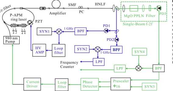
The schematic setup of the frequency-stabilized fiber laser is shown in Fig. 1. The mode-locked Er:fiber laser is a ring laser based on P-APM mechanism [9]. The laser de-livers pulse trains of a repetition frequency of 100 MHz at
FIGURE 1 Schematic diagram for the frequency stabilization of the fiber laser comb. The repetition fre-quency was phase-locked to SYN1 by controlling the PZT. The off-set beat signal was detected with single beam f –2 f heterodyne tech-nique right after the HNLF. The offset frequency was phase-locked to SYN3 by controlling the current of the pump laser diode. The residual frequency fluctuation was measured with a frequency counter. Polar-ization controller (PC), synthesizer (SYN), photodiode (PD), band pass filter (BPF), low pass filter (LPF)
1560 nmwith an average power of about 4 mW. A piezoelec-tric transducer (PZT) was mounted on the fiber to control the cavity length. Three sections of the fiber in the laser cavity were stretched by the PZT to increase cavity length variabil-ity. The PZT has a resonant frequency of 68 kHz and can tune the repetition frequency up to about 1.9 kHz with a maximal driving voltage of 150 V.
The output of the laser was amplified to 180 mW by an Er:amplifier with combined forward and backward pumping. The total pumping power was about 700 mW. The broadened pulse trains during the amplification were compressed to a full width at half maximum (FWHM) of 50 fs by using a section of SMF (Corning SMF-28). The oscillator and amplifier were mounted on a 5 mm-thick, 25× 25 cm2 aluminum plate, of which the temperature instability was controlled within 0.1◦C by using a thermal-electric cooler.
An octave-spanning SC was generated from the fiber laser system by splicing an 18 cm-long dispersion-flattened highly nonlinear fiber (HNLF) to the SMF-28 fiber. The HNLF fiber
FIGURE 2 Green line: Supercontinuum generated from the HNLF measured with an optical spectrum analyzer below 1700 nm. The spectrum above 1700 nm was measured with a monochrometr, where power was not cali-brated. Blue line: spectrum after the amplifier, red line: spectrum of the laser oscillator had a nonlinear coefficient of 10.6 W−1km−1, a dispersion of 1.74 ps/nm/km, and a dispersion slope of 0.01 ps/nm2/km at 1550 nm, respectively. The generated SC covers an octave span from 1050 nm to 2100 nm with total power of 160 mW, as shown in Fig. 2.
The CEO beat frequency was detected right after the HNLF by using a simple SBF2F interferometer, in which the interference between f2nand 2 fncombs occurs in a
sin-gle arm as shown in the upper part of Fig. 1. Such a SBF2F configuration had also been used in a Ti:S laser based fre-quency comb [10]. The beat signal of 1050 nm combs from the SBF2F interferometer was chosen to measure the CEO frequency of the ML fiber laser. The 2100 nm comb lines were frequency-doubled with a 1 cm-long periodically poled magnesium-oxide-doped lithium niobate (MgO:PPLN). A ro-tational fiber squeezer was mounted before the HNLF as a polarization controller to optimize the frequency-doubling efficiency. The FWHM of the frequency-doubled comb at 1050 nmwas 5 nm. The comb lines at 1050 nm were filtered
with a 10 nm-wide bandpass filter and their CEO beat signals were detected by an InGaAs photodiode. A beat signal with S/N of 30 dB was measured immediately after the HNLF with a resolution and video bandwidth of 100 kHz. We could de-tect the CEO beat signal for HNLF length from about 15 to 22 cm without further GVM compensation after the HNLF. The maximum beat S/N was obtained with about 18 cm-long HNLF for this SBF2F without GVM compensation config-uration. The GVM between 1050 and 2100 nm combs may reduce the S/N of the CEO beat signal and can be readily com-pensated by splicing a short section of SMF (SMF-28) after the HNLF. The splicing reduced 11% of the output power. Fig. 3a shows the dependence of the beat S/N on the length of the SMF fiber. Typically, a beat S/N of more than about 28 dB in a 100 kHz resolution bandwidth is required to achieve sta-ble frequency control. Figure 3b shows the measured> 40 dB CEO beat S/N after the GVM compensation using a section of 7 cm-long SMF. The beat signal has a FWHM linewidth of about 400 kHz.
The capability of detection the CEO beat signal right after the HNLF without using the dispersion compensation fiber (dc-fiber) means the two components still overlap in the f –2 f interferometer. The difference of the temporal delay between
FIGURE 3 (a) Measured CEO beat S/N vs. the length of the SMF after the HNLF. The line is for guiding the eye. Typically, a beat S/N of more than about 28 dB in a 100 kHz resolution bandwidth is required to achieve sta-ble frequency control. (b) The detected CEO beat signal with 7 cm SMF for GVM compensation (resolution and video bandwidth are 100 kHz)
the two components in the f –2 f interferometer for the inter-ferometers with and without dc-fiber can be calculated from the dispersion curve of the dc-fiber SMF-28 [11] and the re-quired fiber length of 6 cm for maximum S/N ratio, which is estimated to be 828 fs. The comb modes at 2100 nm were generated through the mechanism of fission of higher-order solitons [12]. Their pulse width should be the same as that of the input pulse, which is∼ 50 fs. The frequency-doubled comb at 1050 nm would not have this pulse width, but a pulse width limited by the bandwidth of the frequency doubling. The bandwidth of 5 nm corresponds to a Gaussian pulse with a FWHM of 324 fs. This pulse was estimated to be broadened to 370 fs after the lenses and MgO:PPLN. The pulse width is smaller than the temporal delay generated by the dc-fiber, but we still can detect the CEO beat signal. This means that the di-rectly generated comb at 1050 nm should have a pulse width of at least 828 fs. The broader temporal width of the comb modes at the shorter wavelength had also been observed in the two-beam f –2 f interferometer for a PCF [10]. This may be due to the dispersion of the HNLF and the complex and broad temporal distribution of SC generation in highly nonlin-ear fiber [13].
2.1 Repetition frequency stabilization
The schematic diagram for the stabilization of the repetition frequency and the offset frequency can be found in the lower part of Fig. 1. To stabilize the repetition frequency, the phase of its 10th harmonic was compared with the 1 GHz signal of a synthesizer (SYN1) through an double-balanced mixer. The phase signal was then fed back to the PZT mounted on the laser cavity to control the repetition frequency. To char-acterize the frequency stability, the out-of-loop repetition fre-quency was detected by the second InGaAs detector (PD2). The 10th harmonic was filtered out and then mixed down to 1 kHz with a synthesizer (SYN2). The 1 kHz signal was counted with a universal counter in 1 s of gate time. All the synthesizers and the counters were referenced to a 10 MHz low-noise oven-controlled quartz oscillator, which was phase-locked to a global positioning system receiver disciplined Rb clock. The stability of the 10 MHz reference signal was better than 2× 10⁻¹²for integration time longer than 1 s.
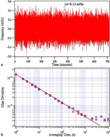
The measured residual frequency fluctuations of the 1 kHz signal is shown in Fig. 4a, which shows one standard devia-tion (1σ) of 0.13 mHz and corresponds to a relative instability of 1.3 × 10⁻¹³. The calculated corresponding Allan deviation in a juxtaposed manner is shown in Fig. 4b, which shows a tracking stability of 1.3 × 10⁻¹³/√τ for integration time τ less than 1000 s. The agreement of the standard deviation and the Allan deviation at 1 s shows the white frequency noise characteristics, which is also confirmed by the 1/√τ depen-dence of the Allan deviation [14]. For white frequency noise, no bias due to the juxtaposed measurement will result for the Allan variance calculation [15]. Meanwhile, counting of the 1 kHz beat signal between SYN1 and SYN2 shows the same stability. This indicates that the measured stability of the repetition frequency is not intrinsic, but limited by the stabil-ity of our measurement system. The higher tracking stabilstabil-ity than the reference standard indicates that a true stability of 1.3 × 10⁻¹³/√τ for the repetition frequency can be reached
FIGURE 4 (a) Residual fluctuations of the 10th harmonic (1 GHz) of the out-of-loop repetition frequency. (b) Allan deviationσy(τ) calculated from
the data in (a) (open circle) and that calculated from the beat between SYN3 and SYN4 (open square). solid line:σy(τ) = 1.3× 10⁻¹³/√τ
by appropriately choosing a reference standard. For similar type of P-APM Er:fiber laser, Benkler et al. demonstrated that their laser is capable to reach 1.4 × 10⁻¹⁴for 1 s integration time by comparing two free-running mode-locked laser to a common continuous wave optical reference [16]. However, they only reached a stability of about 1.3 × 10⁻¹¹for the ac-tively stabilized repetition frequency [6]. Our superior results may be due to the higher resonant frequency of PZT we used (500 Hz in [6], private communication with F. Tauser).
For integration time longer than 1000 s, the Allan devia-tion shows a noise floor of about 3.5 × 10⁻¹⁵. Since the beat signal between the rf reference SYN1 and SYN2 also shows the same noise floor, we believe this is the noise floor of our current measurement system but not the intrinsic limit of the fiber laser comb. Kubina et al. showed that the stability of similar Er:fiber laser comb could reach 2× 10⁻¹⁶ for inte-gration of 10 000 s by comparing two fiber laser combs with a common optical frequency standard, which was limited by the drift of the two mode-locked fiber lasers [17].
2.2 Offset frequency stabilization
The servo loop for the offset frequency stabiliza-tion was reported to be limited by the response of the Er:fiber laser to less than 10 kHz for previous work [5, 18]. To deter-mine the response of the fo to changes in the pump power, we monitored the CEO beat signal with a spectrum analyzer while the pump current was modulated by an external source.
The modulation signal generated a peak-to-peak current modulation of 2 mA, which corresponded to 1.3 mW pump power modulation. Figure 5 shows the CEO frequency excur-sion vs. the modulation frequency. The curve shows mainly the response of the fiber laser, since the current driver has a 3-dB bandwidth of 350 kHz. The 3 dB bandwidth of the laser response was determined to be about 20 kHz, which is compa-rable to the measured 17 kHz for similar P-APM Er:fiber ring laser reported in [8]. The larger bandwidth allowed us to reach better frequency stability as shown below.
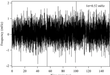
For the stabilization of the offset frequency, both the de-tected offset frequency at 122 MHz and the reference signal from a synthesizer (SYN3) were first prescaled by 16 and their phase was then detected with a digital phase/frequency de-tector. The phase signal was fed back to the current driver to stabilize the offset frequency by controlling the pump power of the fiber laser oscillator. The in-loop offset frequency was mixed down to 5 MHz with a synthesizer (SYN4) for the stability characterization. When the SMF was not used after the HNLF for GVM compensation, the measured re-sidual frequency fluctuation of the detected 5 MHz signal with a counter in 1 s gate time was 0.52 mHz (1σ), as shown in Fig. 6. This residual fluctuation could be reduced to 0.42 mHz (1σ) by splicing a short length of SMF after the HNLF to increase the S/N of the CEO beat signal. For the fiber laser oscillator, the measured in-loop CEO frequency does not rep-resent the real CEO frequency of the laser oscillator, since noise generated in the amplifier and HNLF will be fed back to the laser oscillator such that the detected CEO frequency is identical to the reference. But, for the frequency comb inside the supercontinuum, the measured in-loop CEO frequency represents the real CEO frequency of the laser comb after the HNLF, which works for the frequency metrology. The CEO frequency fluctuation alone will affect the frequency in-stability of the fiber laser comb less than 3× 10⁻¹⁸ for 1 s integration time. Thus, the stability of our fiber laser comb is mainly limited by the stability of the repetition frequency. The potential limit of the stability of our P-APM fiber laser will be explored by comparing two synchronized lasers as demon-strated for Ti:S laser by Ma et al. [3]. The residual fluctuation
FIGURE 5 The CEO frequency excursion vs. the external modulation fre-quency applied to the current driver of the pump laser diode. Inset shows the measured CEO beat signals at different modulation frequency with a 100 kHz RBW and 500 ms sweep time (from left to right, no modulation, 80 kHz, 20 kHz, 1 kHz)
FIGURE 6 Residual fluctuations of the stabilized in-loop CEO frequency detected with the direct SBF2F configuration without any further SMF spliced to the HNLF for GVM compensation
of the CEO beat is more than an order of magnitude less than the result published by Washburn et al. [5]. It may be partly due to the wider bandwidth of our laser response of 20 kHz as compared to 4.5 kHz response bandwidth for their figure-8 laser.
Theoretical studies from Newbury et al. showed that the bandwidth of the laser response to the pump power is not determined by that of the Erbium gain medium alone, but determined by the complex dynamics of the interplay be-tween the slow gain medium and the faster laser dynamics. They found that the bandwidth of the laser response can ex-ceed that of the Erbium gain by a factor of (1+ η−1), where η < 1 is a parameter characterizing a nonlinear loss related to the saturation of the self amplitude modulation (SAM) in mode-locked fiber laser [19]. The value ofη is laser system-dependent. Our measured bandwidth of 20 kHz corresponds toη ≈ 1/11.5 estimated by using the response bandwidth of 1.6 kHz for the Erbium gain medium reported in [8]. To the-oretically compare the response bandwidth for different type of laser design is not easy, since direct measurement of the factors affectingη is not available yet. For detail study of the response dynamics for mode-locked fiber laser in theory and experiment is referred to [8, 19].
3 Conclusions
In summary, we demonstrated the frequency sta-bilization of a P-APM Er:fiber laser with a compact con-struction of single beam f –2 f heterodyne technique without
any further delay compensation after the HNLF. This can in-crease the output power of the SC about 11% by avoiding further splicing SMF after the HNLF. We showed the first sub-mHz frequency stabilization of the CEO frequency of a fiber laser comb. The stabilized repetition frequency has an out-of-loop tracking stability of 1.3 × 10⁻¹³/√τ, which is a factor of 16 better than the rf standard used in this work. It is clear that such a high stability can be reached for each comb line with an appropriately chosen reference stan-dard. Development of a compact, potable optical frequency counter with high stability can be possible by utilizing the Er:fiber laser comb with the simplified single-beam f –2 f interferometer.
ACKNOWLEDGEMENTS We thank Y.-C. Cheng for her con-tribution to the electronics used in this work. This work was supported by the Bureau of Standards, Metrology and Inspection, Taiwan.
REFERENCES
1 T. Udem, R. Holzwarth, T.W. Hänsch, Nature 416, 233 (2002) 2 D.J. Jones, S.A. Diddams, J.K. Ranka, A. Stentz, R.S. Windeler,
J.L. Hall, S.T. Cundiff, Science 288, 635 (2000)
3 L.-S. Ma, Z. Bi, A. Bartels, L. Robertsson, M. Zucco, R.S. Windeler, G. Wilpers, C. Oates, L. Hollberg, S.A. Diddams, Science 303, 1843 (2004)
4 J.W. Nicholson, M.F. Yan, P. Wisk, J. Fleming, F. DiMarcello, E. Mon-berg, A. Yablon, C. Jørgensen, T. Veng, Opt. Lett. 28, 643 (2003) 5 B.R. Washburn, S.A. Diddams, N.R. Newbury, J.W. Nicholson,
M.F. Yan, C.G. Jørgensen, Opt. Lett. 29, 250 (2004)
6 F. Adler, K. Moutzouris, A. Leitenstorfer, H. Schnatz, B. Lipphardt, G. Grosche, F. Tauser, Opt. Express 12, 5872 (2004)
7 T.R. Schibli, K. Minoshima, F.-L. Hong, H. Inaba, A. Onae, H. Mat-sumoto, I. Hartl, M.E. Fermann, Opt. Lett. 29, 2467 (2004)
8 B.R. Washburn, W.C. Swann, N.R. Newbury, Opt. Express 13, 10 622 (2006)
9 K. Tamura, E.P. Ippen, H.A. Haus, L.E. Nelson, Opt. Lett. 18, 1080 (1993)
10 H. Ahn, R.-H. Shu, R.S. Windeler, J.-L. Peng, IEEE Trans. Instrum. Meas. 54, 767 (2005)
11 http://doclib.corning.com/OpticalFiber/pdf/pi1344.pdf, SMF28 and SMF-28e have same dispersion curve. Dispersion at 1050 and 2100 nm was extrapolated
12 A. Husakou, J. Herrmann, Phys. Rev. Lett. 87, 203 901 (2001) 13 J.M. Dudley, X. Gu, L. Xu, M. Kimmel, E. Zeek, P. O’Shea, R. Trebino,
S. Coen, R.S. Windeler, Opt. Express 10, 1215 (2002)
14 D.W. Allan, IEEE Trans. Ultrason. Ferroelectr. Freq. Contr. 34, 647 (1987)
15 P. Lesage, IEEE Trans. Instrum. Meas. 32, 204 (1983)
16 E. Benkler, H.R. Telle, A. Zach, F. Tauser, Opt. Express 13, 5662 (2005) 17 P. Kubina, P. Adel, F. Adler, G. Grosche, T.W. Hänsch, R. Holzwarth, A. Leitenstorfer, B. Lipphardt, H. Schnatz, Opt. Express 13, 904 (2005) 18 J. Rauschenberger, T.M. Fortier, D.J. Jones, J. Ye, S.T. Cundiff, Opt.
Express 10, 1404 (2002)
19 N.R. Newbury, B.R. Washburn, IEEE J. Quantum Electron. QE-41, 1388 (2005)
![[2015-Fall] WNFA lab1 - CamCom](data:image/gif;base64,R0lGODlhAQABAIAAAP///wAAACH5BAEAAAAALAAAAAABAAEAAAICRAEAOw==)