Proceedings of the 2000 IEEE lntemational Conference on Robotics & Automation
San Francisco, CA April 2000
Holonic Supervisory Control and Data Acquisition Kernel for
21‘‘ Century
Intelligent Building System
Li-Chen, Fu and Teng-Jei, ShihComputer Science & Information Engineering, National Taiwan University, ROC
Abstract
The Intelligent Building/Home System (IBS) enhances the human life style. It makes our life more comfortable, efficient, and safety. With increasing of computer, communication network, and building automation protocol, the IBS has been
possible to implement in every building soon. The critical
problem to the IBS that can be a popular one is that how to
construct the IBS quickly and efficiently. In this paper we
proposed a systematical method and model to construct an IBS and a control kernel to integrate it. Afier that, the IBS
will be easy to construct and it will be a flexible and scalable system.
1
Introduction
Supervisory Control and Data Acquisition (SCADA)
[SI
has been invoked by a lot of systems for controlling and monitoring mechanism. Traditionally, SCADA has a hierarchical structure with four layers, namely field layer, control layer, man machine interface (MMI) layer, and storage layer. There are many existing commercial solutions for SCADA of which a most popular one is Wondenvare Factory Suit 2000. Almost all SCADA solutions in the market offers a graphical environment for monitoring and control and a DDE server for data exchange between the MMI layer and the control layer. The control layer can be programmable logic control (PLC), mess flow control (MFC), etc. where as the field layer can be analog I/O or
digital
U 0
over a field-bus. The Echelon Co. offers a standard field-bus namely LonWorks with LonTalk protocol, which can be used to replace the existing field-bus such as RS485 [7] step by step. Such field layer has been widely adopted in the SCADA in nowadays market.By the progress of the PC, the PC-based control [21] has been brought to attention, which is now a popular research topic. Basically, a PC-based control system in a network environment forms a distributed control system with distributed intelligence [12]. The primary advantage of such network PC-based control is its powerful aggregate calculating capability, which gradually revolutionize the traditional SCADA. The master computer in the SCADA system need not handle everything in collecting field data or executing SCADA command. Often, these two jobs are assigned to remote terminal units (RTUs) [ 5 ] , each of which is a powerful computer either in charge of field data collection or command execution. It is noteworthy that the master computer (Master Terminal Unit (MTU)) [ 5 ] only has
to communicate with all RTUs when assign the SCADA requests. The MTU can be even placed in a remote location. Given such a new arrangement for computers, a new idea for SCADA appears. That is, there exists a kemel between MTU and RTUs for handling the information processing and for managing the MTU, RTUs and the field devices, too. All units in this new SCADA system are equipped with two functional features, namely, autonomy and cooperativeness.
This paper endeavors to develop an agile SCADA in a network PC-based control environment so that the Intelligent BuildingMOme System (IBSBHS) can be an excellent example for using this system. This agile SCADA system will have advantages such as “Quick Forming of Control Commands”, “Easy of Scaling and Grouping Field Devices”, “Single Operation Control”, “Parallel Request Processing”, and “Easy to Construction of the SCADA System”, etc. which are however not supported in the existing SCADA systems.
In order to provide the hnctional capabilities such as autonomy, cooperativeness, agility in a SCADA system, we develops an agile SCADA mechanism, namely, Holonic SCADA with SROCK (Supervisory Request Oriented Control Kemel). Note that a Holonic system [6] is a multi agent system, where each of them has the capability of autonomy and cooperativeness. For this Holonic SCADA system, MTU only needs to build a graphic control interface, whereas RTUs and filed devices are constructed by holons.
2 Intelligent Building System
The term “Intelligent Buildings” was first used in the United States in the early eighties and the former Intelligent Building Institution in Washington gave it a definition as [I]:
“An Intelligent building is the one, which integrates various systems to efectively manage resources in a coordinated mode to maximize: tactical performance, investment and operating cost saving, andjlexibility. ”
Such a view for intelligent buildings emphasizes on integration of various subsystems such as “fire system”, “security system”, “access control system”, “lighting control system”, “HVAC system”, “lift monitoring system”, “CCTV system”, etc. Traditionally all of these subsystems were stand-alone and had their own controller and communication protocol, which unfortunately lead to complex wiring (as shown in Fig 2-1) in nowadays modem building and expensive construction cost for that.
Figure2-3lnteractive Architecture in IBS Figure 2-1: Traditional Architecture of Stand-alone
Systems in Intelligent Buildings
The first generation intelligent buildings tried to solve these problems by applying uni-controller and field data bus and by establishing the building automation protocols such as LonWorks and BACnet [2] which can accommodate an open and distributed control environment. Thus, the technique of adopting uni-controller and field data bus over an open and distributed control system offers a total solution for integration of various subsystems in intelligent buildings and makes the wiring much easier and the construction cost much lower. (Figure 2-2).
E3
BvWlng Man.gcmcnl
Q
System SCADA RTUI I
c9
h v l c t Contmlkr DIvkc Controller Devlcc Controller D e v I ~ ~ ~ n t r o U ~ r
D L D C L D.G, D e L l C O
Node NOdC Node “le
Figure 2-2 Integration Architecture of Open and distribute Control Environment Systems in Intelligent Buildings
More recently the “Intemational Council for Building Research Studies and Documentation”(C1B) Working Group W98 on Intelligent and Responsive Buildings state the following [ 11:
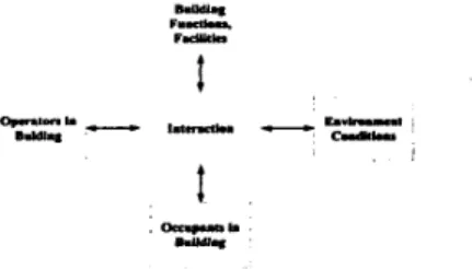
“An Intelligent Building is a dynamic and responsive architecture that provides evely occupant with productive, cost eflective and environmentally approved conditions through a continuous interaction among its four basic elements: places dfabric, structure, and facility), processes (automation, control, systems), people (services, users) and management (maintenance, performance). ”
In comparison with the previous concept on intelligent buildings, such new generation ones emphasize on interaction among building facilities, building functions, operators in building, occupants in building, and environment conditions (Figure 2-3) besides the integration of various subsystems.
This revolutionary notion yields a Responsive Building with artificial intelligence and multi sensing [3] which will also be the trend of intelligent buildings in the next 21” century.
Just imaging that when one enters a building, he will soon become a real part of it rather than just accept what it gives to you. This should be a wonderful idea. A building should not only be a passive architecture anymore. Human may joins into the Building Basic Utilities Cooperation Mechanism (BBUCM) [3], which integrate all subsystems in an IBS through Human Building Interface (HBI). The inputs and outputs of BBUCM and HBI are macro-request and responses, respectively (Figure 2-4).
Figure 2-4 The Model of Building Basic Utilities Cooperation Mechanism
The macro-request is a group of control commands whereas according to the macro-request derivation, we can classifL them into three kinds, namely:
Supervisor Request: It is a macro-request made by building operators to control device nodes or to change the behavior in BBUCM.
Occupant Request: It is a macro-request to IBS made by occupants. Building supervisor formats the occupant requests meanwhile the occupant can only issue the request formatted by supervisor.
System Request: It is a macro-request made by the IBS itself so as to achieve or to complete some pre-set system objective.
we classify the macro-requests according to the functionality, there are three functional domain;, namely “strategic domain”, “tactical domain” and “operational domain” [20]. The following are their respective descriptions.
1. Strategic Domain: Strategic request in intelligent 2642
building system is mainly sent by building administrators, occupants or system itself for strategic building management.
2. Tactical Domain: Tactical request in an intelligent building system is mainly sent by system for meeting the strategic goal.
3. Operational Domain: Operational request in intelligent buildings is mainly sent by system.
In this paper, we will discuss the relationship among the strategic, tactical and operational domain requests in the intelligent building system.
3 HSCADA Architecture in IBS
In this section, we present a prototype of HSCADA Model to demonstrate how an IBS system is constructed from Figure 3-5:
,. -. .e"-
w UT-
Figure 3-5 HSCADA Model for Intelligent Buildings
MTU holon is joined into SROCK through the communication module.
0 Strategic and user request library module: The module reads the usable strategic and user requests from the SROCK through the communication module. 0 Request issuing module: This module sends the
available macro-request to SROCK from the request library so that the supervisor or the user can perform system control or data analysis.
Communication module: This module is in charge of the message passing between the RTU holons and SROCK.
Registration module: This module sends the registration message to the SROCK to notify that a new RTU holon is joined into SROCK through the communication module. After the RTU holon joins into the SROCK, the RTU holon, it send the "join node" message of all the firmware holons which are covered by the RTU holon to the SROCK.
Request execution with holon broker: This module accepts the request from SROCK and brokers the matching holon to serve the request. The request will change the values of the rule variables in the matched holon.
0 Common database module: This module offers an environment for data exchange so that the RTU holon can communicate with the subordinate firmware holons.
The prototype of the holon structure in the
firmware
layers is shown in Figure 3-7 and each module of the firmware holon is described as follows:
Each module of the RTU holon is described as follows:
0
0
The RTU holons and the MTU holons with the SROCK form the software holarchy in the HSCADA mechanism. The MTU holon is the interface between the supervisor or
user and the intelligent building system whereas the RTU holon is responsible for collecting the remote data and for executing the control commands execution unit. The prototype of these two holons is shown in Figure 3-6.
I 1
MTU U d m RTU Holoi
Figure 3-6 The Prototype of the MTU Holon and RTU Holon
Each module of the MTU holon is described as follows:
0 Communication module: This module is in charge of
the message passing between the MTU holons and SROCK.
0 Registration module: This module sends the registration message to the SROCK to notify that a new
Figure 3-7 Prototype of Control and Field Device Holon
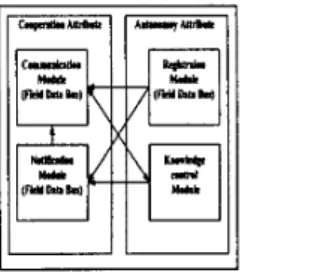
Communication module: This module is in charge of the message passing to the other cooperative holons or
the data exchange through the common database over the field bus. This module always works with the knowledge control module, which keeps the control rules and the rule variables.
Knowledge control module: This module keeps the control rules and the rule variables so that the holons can be controlled by the other one through the communication module. By the change of value in the rule variables, different control rules will be executed. Different layer of HSCADA has different knowledge model.
Registration module: This module sends the registration message through the communication module to the common database and then an RTU 2643
holon will be added to the SROCK as a node in the HSCADA graph.
Notification module: This module notifies the status of the holon to the SROCK through the communication module.
A holon will be a holarchy when the group of holons in the sub-layer are linked to that holon. We can say that holarchy is a dynamic grouping method in HSCADA mechanism according to the functionality or space. For example a council holon can be linked by safety holon or to some others. If it is linked to the safety holon, then the safety holon will work in that council. The holarchy after removal of the preceding holon remains a holarchy unless all linkages are removed.
The HSCADA model offers a rapid and efficient method to model the IBS with HSCADA mechanism, which is a distributed and cooperative intelligent system with supervisory control. This model constructs a mechanism of system management and system control. It offers an information graph, namely, HSCADA graph for system management such as holon management and request management. In system control, it offers a layer structure with holonic concept, where this feature allows the distributed and cooperative system with supervisory control to be built easily. The supervisory request oriented control kemel (SROCK) and the RTU holons integrate the IBS with HSCADA mechanism[8] [IO], where RTU holons collect the remote field data and execute SCADA commands meanwhile SROCK is a control kemel. Both of them will be discussed in the next chapter. In HSCADA model, SROCK with RTUs and MTUs can be deemed as a software holon or holarchy.
4
SROCK: Supervisory Request Oriented
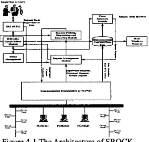
Control KernelSROCK is the software holon or holarchy in the HSCADA model. In this chapter, we will discuss the detailed structure of SROCK and explain how it works in HSCADA model with RTU holons, MTU holons, control holons, and field device holons. The architecture of SROCK is shown in Figure 4- 1 : a,.”.”””.”. --E-r I I I
=f:
.-
A
e . . - P V H M l PVHUl -Ut ~ *.- U IFigure 4-1 The Architecture of SROCK
SROCK has seven main parts, namely, “communication module”, “HSCADA graph editor module”, “request fetching, dispatching, executing module”, ”GUI module”,
“holon management module”, “request management module”, and “monitor and error recovery module”. Communication module is mainly in charge of data exchange between the kemel and the other holons in the intelligent building system with HSCADA mechanism. SROCK can adopt the communication technique such as “DDE” or “TCPLF’”. The HSCADA graph is a very important data structure in SROCK for the intelligent building system with HSCADA mechanism. HSCADA graph is a directed graph, which records important information in the firmware holons. This graph is used for four modules in SROCK, namely, “holon management module”, “request fetching, dispatching, execution module”, ”monitor and error recovery module”, and ”request management module”. All of these modules retrieve the information of the intelligent building system with HSCADA mechanism from the HSCADA graph. The usage of HSCADA graph of each module is
described as follow:
Holon management module:
This module
mainly records the state of firmware holons. There
are four states of
a holon in a life cycle,
namely, new, idle, active, and dying state. The knowledge of the holon state out of the four is possible through the retrieval of the updated information in the HSCADA graph.Request fetching, dispatching, and executing module: This module retrieves the information of the relevant holon states which will be used in the SCADA control request. For example, if a request needs holon-1 and holon-2 for some objective, holon-1 and holon-2 should be all active. If the holon is unfortunately in dying state, then the error recovery request will be execute first.
Monitor and error recovery module: This module retrieves the holon status which records the requests in that holon for the monitor module and retrieves the state of holons in HSCADA model for the error recovery module. If the holon is in dying state, then an error recovery request will be issued.
Request management module: This module supports request editor to edit the strategic requests, user requests, and system requests. The tactical requests are formed by retrieving the firmware holon information from the HSCADA graph.
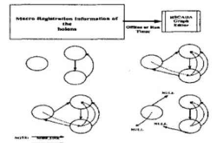
In the HSCADA Graph, a node represents a firmware holon, and an arc represents the holarchy link. To add a node to the HSCADA graph means that to join a new firmware holon with either cooperative or hierarchical structure to SROCK, and to delete a node is simply the converse of the above operation. After a new node joins the HSCADA graph, the node information can be updated in the run-time mode. Furthermore, the dynamic holon grouping method adopts the run-time update of the holarchy links. All the former three graph operations are performed by RTU holons. Figure 4-2 shows the steps of joining and deleting nodes and arcs in the HSCADA graph:
....wT,"Y.-
Figure 4-2 Steps of Joining and Deleting Nodes and Arcs in the HSCADA Graph
The request manager is mainly in charge of creation and management of the strategic request, user request, and system request. Strategic, user, and system request are the request macro of tactical requests, and each tactical requests is formed according to the information kept in the node of the HSCADA graph. A macro-request is composed of several tactical requests. The following is an example, which is the power saving macro-request for an IBS:
Sbategic Request: Economic Power Saving Macro-request Setlime Light Off-lime OSOO I
Setlime Light On-lime I700 1
Setlime Elevator Ml-Off-Time 2400 I Setlime Elevator MI-On-lime OSOO I Setklue BrightnessThreashold 2000 I SelYolue HumidiryThreashold 60 I Setvalue TemuerahtreThreashold 28 I
The SROCK fetches the macro-requests from two sources. That is, the strategic and the user requests are issued by the supervisor or users in the IBS, whereas the system request is issued by the kemel itself. These requests are first fetched and put into request queue, which is a multilevel queue where the priority decides their level. Figure 4-3 shows the procedure of fetching the requests into the request queue:
Request
Request Tsetleal Request
M a c r o Multilevel Queue
Request
Figure 4-3 Request Fetching Model
Multilevel queue is a queuing model used in process schedule in the operation system [18], is very useful in SROCK. Queue is a FIFO data structure which adopts the
time priority to keep the item in it. Multilevel queue keeps the item not only dependent on time priority but also on the other kinds of priority that are set by users. Besides time priority, the priority we adopt in this paper is the execution limitation of the request. There are three kinds of limitation, namely, common, immediate, and real-time, which are described as follows:
Common: A request with common priority means that there is no execution limitation of this request. If a request waits in the common queue for a period exceeding the starvation threshold, then it will be upgraded to the immediate queue
Immediate: A request with immediate priority means that it should be done in a short period of waiting time. The request in this level need not be and can not be upgraded to the real-time level.
Real-Time: There are very few of the requests assigned to this level of waiting queue in intelligent HSCADA because too many real-time requests will deteriorate the real-time performance of those request in the system. In an intelligent building system with HSCADA mechanism, the error recovery request and emergency response request are the example of the real-time requests.
2645
In intelligent biilding systems with HSCADA mechanism, a break-down firmware holon should only affect the whole system in the shortest period of time. SROCK offers an error recovery mechanism. The error recovery in HSCADA mechanism includes two domains, one is physical domain and the other is software domain which are described as below:
Physical domain error recovery: There are two kinds of solutions, one is backup holon, and the other is off-line replacement. The first one is more efficient but more expensive whereas the second one is less expensive but more time consuming. The first physical error recovery mechanism supports the backup holon, which is linked to the system with HSCADA mechanism and joins into the HSCADA graph without any linkage. This makes the HSCADA graph with an isolated node. The second one should replace the real device and link it to the system again, but should not replace the node in HSCADA graph except updates its state to the new state only.
Software domain error recovery: In HSCADA mechanism, when a holon breaks down, the request assigned to that holon will be kept in the waiting queue until the error recovery request to that holon is finished. After the error recovery request is completed, the request, which is blocked in the waiting queue, will be assigned to the execution queue to execute the request with the new holon again.
5
Experiment and System Evaluation
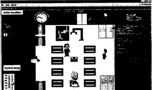
In this paper a simulation example uses the InTouch to implement the firmware holons which is shown in Figure 5- 1 . The InTouch is the graphic control and monitor software that supports a common database, namely InSQL. In this simulation example, we ignore the field data bus, and the real field device. it only simulates the behavior of them in an intelligent building. The simulation field device and control holons communicate with the RTU holons through the dynamic data exchange (DDE). This is the same as the real
work. There are many SCADA solutions in the market [5]. Table 5- 1 shows the advantages of the HSCADA mechanism which are not totally supported by the available SCADA solutions.
6
Conclusion
In this paper, a prototype of HSCADA mechanism is provided and validated in a simulation IBS, meanwhile the prototype of the holons in HSCADA model are provided. There are two main holons in HSCADA mechanism, namely software and firmware holon. Software holon includes three sub-holons, namely, MTU holon, RTU holon, and the kernel SROCK and the software holon is in charge of software level control and data collection. The firmware holon is controlled and monitored by the software holon. The kernel SROCK constructs the relationship between software and firmware holons, that is the HSCADA mechanism is a distributed processing and central control environment via SROCK. The features of the HSCADA IBS system are flexible, scalable, and re-configurable and it is easy to integrate by the SROCK.
Figure 5-3: The Simulation of an Intelligent Building
Table 5-1: The Advantages of HSCADA Mechanism
Features
I
Traditional SCADAI
Holonic SCADAsupport
References
[ l ] T. Derek J. Clements-Croome. “What do we mean by intelligent Buildings?” Journal of Automation in
Construction, Vol. 6,395-400, 1997
[2] Steven T. Bushby. “BACnet: a Standard Communication Infrastructure for Intelligent Buildings,” Journal of Automation in Construction,
Walter M. Kroner. “An Intelligent and Responsive V016,529-540, 1997
[3]
Architecture,” Journal of Automation in Construction,
M.D.Clapp, “Tactical Director. Building Management Systems Past, Present, and Future,” Journal of
Measurement Control, Vol. 29, Dec. 1996, Jan. 1997. AdAstra Research Group, Ltd, http://www.adastra.ru V016,381-393, 1997
[4]
[5]
[6] Holonic Solutions, http://www.holon.com.au
[7] G. Clark
,
P. Mehta.
“Artificial Intelligent and Networking in Integrated Building,” Journal of Automation in Construction, Vol. 6,481-498 1997 Yehuda E. Kalay, Lachmi Khemlani, JinWon Choi, “An integrated model to support distributed collaborative design of buildings,” Journal ofAutomation in Construction, Vol7, 177-188, 1998 91 Echelon Co. LonManagec LonMaker User’s Guide 101 M. Alshawi, J. Underwood. “Applying object-oriented
analysis to be the integration of design and construction,” Journal of Automation in Construction,
111 MARTIN FOWLER, KENDALL SCOTT, “UML DISTILLED: Applying the Standard Object Modeling Language”, Addison- Wesley, 1998
121 George P. Lekkas Nicholas M. Avouris, and George
IC.
“Papakonstantinou. “Development of Distributed Problem Solving System for Dynamic Environments,”
IEEE TRANSACTION ON SYSTEMS. MAN, AND CYBERNETICS. VOL. 25, NO. 3. MARCH 1995 [13] McFarlane, D.
,
Marett, B.,
Elsley, G and Jarvis,D.
“Application of Holonic Methodologies to Problem Diagnosis in a Steel Rod Mill,” IEEE TRANSACTION
ON SYSTEMS. MAN, AND CYBERNETICS. VOL. 1, OCT. 1995
[14] Simon, H.
,
“The Science of The Artificial”, MZTPress, Cambridge, MA. 1990El51 Bengoa, A. , Gluch, S. , Jacobs, H. J. and Bueno,
R.
,
”An Approach to Holonic Components in Control of Machine Tools”, Annals of the CIRP, Vol. 45, No. 1,[16] Ng, A.H.C.
,
Yeung, R.W.H. and Cheung, E.H.M.,
“HSCS -the Design of a Holonic Shopfloor Control Systems”, Proceedings 1996 IEEE Conference on
Emerging Technologies and Factory Automation,”
[17] B. KADAR,
*
L. MONOSTORI, E.SZELKE, “An object-oriented framework for developing distributed manufacturing architechture,” Journal of IntelligentManufacturing Vol. 9, 173-179, 1998
[ 181 SILBERSCHATZ GALVIN, “OPERATING SYSTEM CONCEPTS’. Addison- Wesley, Fourth Edition [19] Mark Allen Weiss, “Data Structures and Algorithm
Analysis in C+”. Weiss
[20] Liu, Song-Han, and Li-Chen Fu, “Multi-agent Based Control Kernel for Flexible Automated Production System,” Proceedings IEEE International Conference
on Robotics and Automation, 1998
[21]
Valckenaers, P.,
Van Brussel, H.,
Bongaerts, L. and Wyns, J. , 1997, “Holonic Manufacturing System”,Integrated Computer-Aided Engineering, Vol. 3 , No. 4, [8] Vol. 5, 105-121, 1996 437-440,1996 ETFA’ 96,179-184,1996 191-201, 1997 2646