Design and Analysis of QoS Supported Frequent
Handover Schemes in Microcellular ATM Networks
Kuochen Wang and Lon-Sheng Lee
Abstract—Wireless information networks need to employ small
radio cells to support large user populations. However, this will impose extra burden on network traffic control as a result of fre-quent handover behavior. Existing approaches to support a high handover rate still have cell loss and cell out-of-sequence penalty while the handover is in progress.
This paper proposes a novel handover protocol that can avoid cell loss and guarantee cell sequence. It can enhance the perfor-mance of a microcellular asynchronous transfer mode network. By multicasting cells to a new base station before handover, our scheme can avoid cell loss and support a nonoverlapping microcell environment as well. The multicast of signaling messages during handover is to coordinate the cell transmission order between the old base station and the new base station to guarantee cell sequence. A formal representation of the handover protocol using finite-state diagrams has been developed to specify and verify the protocol. To guarantee quality of service, we present a hierarchical wireless call admission control to limit the number of in-progress connections and to prevent radio channel congestion. Mathemat-ical models have been developed to analyze two quality-of-service parameters: handover dropping probability and forced termination
probability. Experimental results show that our hierarchical
wireless call admission control can effectively lower the handover dropping probability and the forced termination probability in comparison with the single-layer wireless call admission control.
Index Terms—Asynchronous transfer mode (ATM) network, cell
loss, cell out of sequence, handover, microcell, multicast, wireless call admission control.
I. INTRODUCTION
W
IRELESS communication service demand is growing rapidly. In order to serve a high user population in a limited spectrum, using dense grids of microcells and pic-ocells is one of possible schemes. While small cells relieve the capacity problem, frequent movements of mobile users across cell boundaries pose a big network control challenge:handover. Since a handover protocol involves rerouting,
termi-nating, and establishing connections, they result in much time consumption during the handover process. This reduces the system performance of a wireless network. Other problems that result from the handover process are cell loss and cell out of sequence [1]. A fixed network may misroute a cell (packet) to the old base station (BS) before the fixed network reestablishes a connection to the new BS. It will result in cell loss. The cell out of sequence occurs as a result of the cells from a mobile
Manuscript received July 14, 1997; revised November 29, 2000. This work was supported by the MOE Program of Excellence Research, Taiwan, R.O.C., under Grant 89-E-FA04-1-4.
The authors are with the Department of Computer and Information Science, National Chiao Tung University, Hsinchu, Taiwan 30050, R.O.C. (e-mail: [email protected]).
Publisher Item Identifier S 0018-9545(01)06046-7.
host (MH) traveling via the new BS reaching the end point before the cells traveling via the old BS.
The asynchronous transfer mode (ATM) network is a rep-resentative fixed network technology. It is designed to support voice, video, and data services in one protocol. In this paper, we will take an ATM network as a backbone and combine it with a wireless network. Based on this network, we will propose a new handover protocol that can support a high handover rate [20] and handle cell loss and cell out of sequence in a micro and nonoverlapping cell environment.
The organization of this paper is as follows. Section II reviews existing approaches while Section III describes our proposed handover scheme. In Section IV, we present a formal represen-tation of our scheme. Performance analysis and experimental re-sults are shown in Section V. Section VI gives some concluding remarks.
II. EXISTINGAPPROACHES
Several existing handover protocols are aimed at a single problem: either supporting microcell architecture or guar-anteeing transmission quality. In a traditional wireline ATM network, the user is stationary throughout the connection life-time and the traffic of the call connection is standing [7]–[9]. However, in a wireless ATM environment (see Fig. 1), when a mobile user has handed over to a new BS, the connection must be rerouted each time. Because of the frequent handover, the call processor may need to become involved many times during a mobile connection lifetime, and it would cause a considerable burden on the processing of cellular controllers [2]. Acampora and Naghshineh propose a model for mobile-executed han-dover in cellular ATM networks suited for a small radio cell system [3], [6]. In this model, a mobile connection call setup procedure creates a virtual connection tree and covers a large geographical region [3], [6]. Because of the preestablished connection path at call setup time, the MH does not need to have a rerouting procedure during the handover process each time. In this way, the MH can be provided a fast and frequent handover in the geographical region without causing any burden on network traffic. However, it cannot handle misrouted cells and cell out-of-sequence problems [10]. References [11] and [12] adopt a group-based framework to ensure that an MH can move rapidly between radio cells. Any message destined for the MH is multicast to all the BSs of the group [11]. This approach consumes a large volume of network bandwidth to ensure that messages are not lost.
Reuven et al. center on these problems and propose a han-dover protocol to resolve the penalty [1]. The protocol ensures that as long as an MH moves in the same region, all packets will 0018–9545/01$10.00 © 2001 IEEE
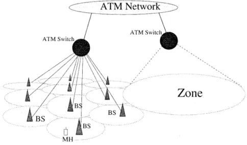
Fig. 1. A wireless ATM network infrastructure.
Fig. 2. An example mobile connection.
receive in order and have no data loss [1]. It is based on a packet forwarding method to prevent packet loss. They also propose another protocol to preserve the order of packets. It can assure that the packets from the old BS will reach the gateway faster than the new one. That is, this handover protocol can guarantee the quality of service. However, the handover process requires including packet forwarding and it will lengthen the processing time to complete the handover protocol. Thus this protocol will not be suitable for a frequent handover environment.
To prevent handover dropping, some radio channel assign-ment schemes [13]–[16], such as fixed channel assignassign-ment and dynamic channel assignment, and wireless call admission control schemes [17]–[19] have been proposed. These channel assignment schemes reserve a proportion of guard channels for handover calls or give handover calls higher priorities than new calls. They maintain cell state information, such as predictive cell resource requirements, as a criterion for wireless call admission control. However, if too many mobile users cluster in a small geographical region, these schemes will not effectively lower the handover dropping probability as a result of heavy loading of radio channels. Thus, based
on our network infrastructure, we will propose a hierarchical wireless admission control to avoid the radio congestion and to guarantee the predefined QoS.
III. DESIGNAPPROACH
In this section, we will design a novel handover protocol that has low-latency processing time and supports high frequent han-dover in a micro and nonoverlapping cellular environment. Our protocol can also avoid cell loss and maintain cell sequence. The network model is composed of an ATM fixed network, ATM switches, links, and BSs. As illustrated in Fig. 1, some BSs link to an ATM switch. Each BS cover a cell, and those cells under the same switch form a large region named as a zone [5].
A. Connection Setup
We will focus on building a connection; the detailed call setup procedure is not in the scope of this paper. In Fig. 2, we assume that an MH is in BS1. We refer the BS to which the MH is currently connected as the mobile user’s access point [3]. If the MH is in one cell, those cells that are around this cell are named
as adjacent cells, and those BSs in adjacent cells are referred to as adjacent mobile access points.
We first consider the case of a mobile connection involving an MH and a fixed host. When creating a new mobile connec-tion, the call setup procedure will be executed in two steps. As the thick lines show in Fig. 2, first, a path from a fixed host to switch A is set up, and secondly, seven paths from switch A to the seven BSs are set up for this connection. That is, one path is from switch A to BS1 and the others are from switch A to the adjacent mobile access points of BS1. These seven preestab-lished paths form a mobile connection tree. Switch A is the root and the associated BSs are the leaves of the tree. The geograph-ical region covered by these seven cells is referred to as a
mo-bile connection region. The MH can use the assigned virtual
channel identifiers (VCIs) to communicate with the network. At any time, only the path between switch A and BS1 is actu-ally in use while the other preestablished paths are used during the handover process. A mobile connection tree is similar to a one-to-many multicast tree. For the case of a mobile connection involving two MHs, each connection end is a mobile connection tree.
B. Handover Protocol
We will describe an intraswitch handover protocol for the mo-bile connection regions involved in the handover that are in the same zone and an interswitch handover protocol for the mobile connection regions involved in the handover that cover different zones. We will use emphasized characters to represent signaling messages.
1) Intraswitch Handover Protocol: In order to guarantee the
quality of service, we will discuss the handover protocol to pre-serve cell sequence and to avoid cell loss separately.
a) Handover protocol for traffic from a switch to an MH: As shown in Fig. 2, the MH is currently communicating
with the fixed ATM network via BS1. A mobile connection tree has been created for this MH from the root (switch A) to the BSs (BS1-BS7). Without loss of generality, we assume that the MH will move from BS1 to BS2. A new mobile connection tree will be created during the handover, and BS1–3 and BS7–10 will be the leaves of the new connection tree. The signaling message flow is presented in Fig. 3. The proposed protocol to avoid cell loss is described as follows.
a) When the MH detects the receiving channel strength di-minishing, it initiates a FLOOD message via BS1 to re-quest the root of the mobile connection tree to multicast the incoming cells to all leaves, not only to the mobile user’s access point. At this time, the MH begins to search a new available radio channel for handover.
b) Switch A responds this message by multicasting the downward cells to BS1–BS7.
c) The MH gets a new available radio channel and initiates a JOIN message with the next expected cell sequence number ( ) to the new base station (BS2). BS2 re-sponds the JOIN message by issuing REROUTING and
CHANNEL RELEASE to switch A. At the same time,
BS2 also sends subsequent cells, which were multicast earlier to the MH via the new radio channel.
d) When switch A gets the REROUTING message, it inspects the topology of the zone and realizes that this handover is an intraswitch handover. The switch activates a SETUP message to BS8–10 to establish a new tree and send a
RELEASE message to release the virtual channel
connec-tions from switch A to BS4–6. The old virtual channel connections to BS1, BS3 and BS7 will still be used in the new tree. At this time, the downward cells are still mul-ticast to the mobile connection region until switch A re-ceives a STEADY message.
e) The MH continues to sense the strength of the new channel. If the channel strength becomes strong enough, the MH concludes that it has been away from the cell boundary and will send out a STEADY message to inform switch A. On the other hand, if the channel becomes weak gradually, the MH will search for another channel for handover again.
f) After switch A receives the STEADY message, it stops multicasting and just sends the subsequent cells to the mo-bile user’s current access point (BS2).
The signaling flow mentioned earlier can guarantee the misrouted cells eventually received by the MH. When the MH moves back and forth between cells, this protocol also can provide a fast handover without losing cells.
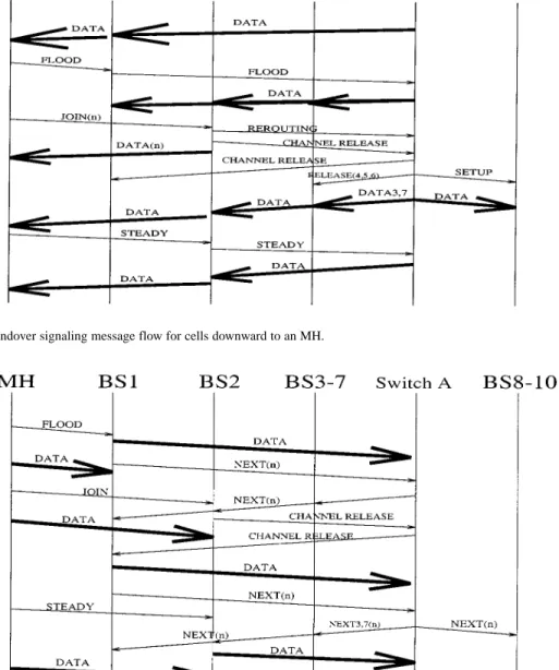
b) Handover Protocol for Traffic from an MH to a Switch: The signaling message flow is illustrated in Fig. 4. We
describe this protocol as follows.
1) When BS1 receives a FLOOD message, BS1 acknowl-edges that the MH will have a handover at any time. How-ever, the MH still sends out cells to BS1. In order to pre-serve the cell sequence, whenever BS1 flushes out the last buffered cell, it issues a NEXT message to tell switch A that there is no cell in BS1. The NEXT message also car-ries the next cell sequence number ( ) that BS1 will send. Switch A responds to this message by multicasting the message to all leaves of the tree.
2) At this time, the MH joins to BS2 and send out cells to BS2 via the new radio channel. However, these cells will be buffered at BS2 and will be triggered to be sent upwardly to switch A by a NEXT message received from switch A. BS2 then initializes a CHANNEL RELEASE message to inform BS1 to release the previous radio channel.
3) After BS2 gets the NEXT message with “ ,” it sends out the buffered cells to the root of the tree. BS2 will send out the NEXT message whenever it flushes out the buffer for this connection.
4) When BS2 receives the STEADY message, it goes to the steady state and stops issuing the NEXT message. The handover signaling message flow may avoid cells via the new BS transmitted faster than cells via the old BS. Thus, it may guarantee the cell sequence.
2) Interswitch Handover Protocol: We now discuss the case
of an MH moves from Zone I to Zone II, as shown in Fig. 2. We assume that an MH is currently communicating with BS12, and the mobile connection region covers BS6, 7, 11, 12, 13, 15, and 16. BS6, 7, 11–13 belong the same zone under switch
Fig. 3. The intraswitch handover signaling message flow for cells downward to an MH.
Fig. 4. The intraswitch handover signaling message flow for cells upward to a switch.
A, and BS15 and 16 are in another zone under switch B. The MH will move from BS12 to BS16 and create a new mobile connection tree. BS12–13 and BS15–19 are leaves of the new tree. We discuss the protocol in the following two sections.
Interswitch handover protocol for traffic from a switch to an MH: In Fig. 5, the signaling message flow is similar to that
mentioned in the intraswitch handover. It is summarized as fol-lows.
1) The normal data flow goes from switch C passing through switch A to BS12, and then to an MH via a radio link. When the MH detects the radio channel strength’s dimin-ishing, it realizes that the radio channel will be unavail-able and delivers a FLOOD message to BS12 to request the root of the current mobile connection tree (switch C) to multicast the subsequent cells to all leaves of the tree (BS6, 7, 11–13, 15, 16).
2) Switch A receives the FLOOD message, looks up the topology table, knows that some leaves belong to Zone
II, and then delivers the FLOOD to switch B via switch C. At the same time, switch A also multicasts the cells to the leaves, BS6–7 and BS11–13, that are in Zone I. 3) When switch C receives the FLOOD message destined to
switch B, it will relay it to switch B and multicast the cells to switch B. After switch B receives the FLOOD message, it will lookup its topology table and then multicast the cells to BS15 and BS16.
4) After the MH joins BS16 and carries the next ex-pected cell sequence number ( ), BS16 will deliver a
REROUTING message to request switch B to adjust the
old connection tree to a new one and deliver CHANNEL
RELEASE to release the previous channel at the BS12
radio interface. Switch B processes the signaling mes-sage by looking up the topology table, sets up the new joining leaves, and also issues a REROUTING message to switch A via switch C. The REROUTING message will tell switch A to release the virtual channel connection
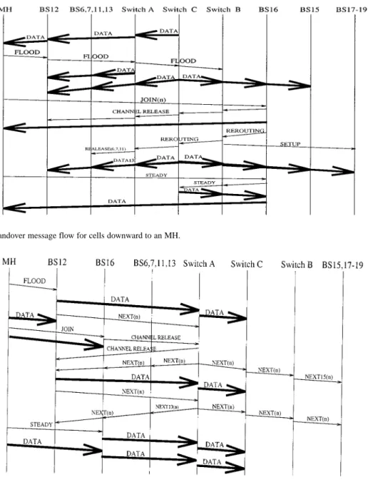
Fig. 5. The interswitch handover message flow for cells downward to an MH.
Fig. 6. The interswitch handover message flow for cells upward to a switch.
Fig. 7. The state diagram of a BS for data flow from a switch to an MH.
from switch A to BS6, 7 and BS11. At this time, the connections are still in the multicast state and the cells are now multicast to the new mobile connection region. 5) Switch C will continue to multicast cells to the new
mo-bile connection region until it receives a STEADY mes-sage from the MH. The STEADY mesmes-sage will enable switch B and C to turn the multicast to a single cast.
By the above protocol, the misrouted cells can be handled in this interswitch handover procedure successfully, and the protocol can also support a user moving back and forth between cells.
Interswitch handover protocol for traffic from an MH up-ward to a switch: The signaling message flow is presented in
Fig. 6. It is similar to that in Fig. 4. The protocol is summarized as follows.
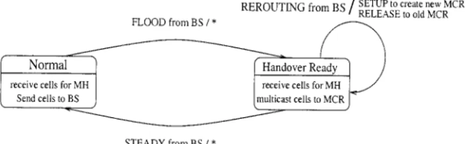
Fig. 8. The state diagram of a switch for data flow from the switch to an MH.
1) An MH sends a FLOOD message to inform BS12 that it may have a handover. After BS12 receives the FLOOD message, whenever BS12 flushes out the buffer for this connection, it will issue a NEXT message with the next expected cell sequence number ( ).
2) Whenever switch A gets the NEXT message, it will mul-ticast the message to the mobile connection region ac-cording to its topology table. There are two situations. The first situation is that the MH does not yet join an-other BS. In this situation, the NEXT message will not af-fect any nodes. BS12 ignores the NEXT message and just sends out the new incoming cells if available. The second situation is the MH has joined another BS. Then the NEXT message with the cell sequence number “ ” will be used to recognize the BS that the MH joins. The BS with a cell whose sequence number is “ ” will respond to the multi-cast NEXT message by sending out the next expected cell. In this way, the cells sent via the old BS can reach the root of the tree (switch C) faster than the subsequent cells via the new BS.
3) As shown in Fig. 6, the first NEXT message initiated by BS12 does nothing because the MH has not joined BS16 and the second initiated NEXT message is multicast to the mobile connection region. This mobile connection re-gion may be a new one or the old one. This is related to the timing sequence of the NEXT, RELEASE, and SETUP messages described above. The NEXT( ) message sent to BS16 will trigger BS16 to send out the buffered cells. 4) A STEADY message will be used to inform BS16 that the
current connection is in the steady state now and needs not issue a NEXT message again, whenever it flushes out its buffer.
As described above, this protocol can guarantee that the out-going cells will be delivered by the ATM switches in sequence despite of the MH handover.
IV. FORMALREPRESENTATION OF THEHANDOVERPROTOCOL We use the notation to mean that message is received by a node and message is sent by the node [1]. If A or B is a “ ,” there is no corresponding message. We divide the protocol by the data flow from a switch to an MH and from an MH to a switch and describe their formal representations, respectively.
A. Formal Representation of the Data Flow from a Switch to a Mobile Host
The state diagram of a BS for the data flow from a switch to an MH is shown in Fig. 7. There are three states:
1) Sleep: the BS does not belong to the mobile connection region;
2) Passive: the BS is a member of the adjacent mobile access points;
3) Active: the BS is in the mobile user’s access point. In Fig. 7, a BS, in a sleep state, receives a SETUP message to request to join the mobile connection region, and then it goes to the passive state. Responding to the received JOIN with
REROUTING and CHANNEL RELEASE messages makes it
enter the active state. The CHANNEL RELEASE message for releasing the radio channel makes it enter the passive state. Finally, the RELEASE message for releasing the virtual channel connection makes it back to the sleep state.
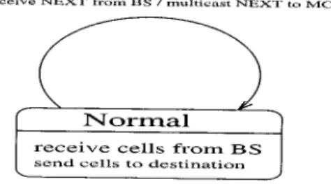
The state diagram of a switch for data flow from the switch to an MH is shown in Fig. 8. There are two states:
1) Normal: the switch just receives cells destined for an MH and routes them to the corresponding mobile user’s access point;
2) Handover ready: the switch receives cells destined for an MH but multicasts them to the mobile connection region. When the radio channel is strong enough, the switch is in the normal state. In this state, the switch is in the single cast state. When the radio channel becomes weak, then the switch goes to the handover ready state. The switch then multicasts cells destined for an MH to the mobile connection region. When the switch receives a STEADY message, the MH will not handover again and the switch then goes back to the normal state.
B. Formal Representation of the Data Flow from a Mobile Host to a Switch
The state diagram of a BS for the data flow from an MH to a switch is shown in Fig. 9. There are four states.
1) Passive: the BS is in the adjacent mobile access point. It just listens for a JOIN message in this state.
2) Active-Buffered: the MH has handed over to the BS, which can receive cells from the MH and then buffer them.
3) Active-Flood: for the data flow, the BS receives a cell from the MH and relays it to the switch. For the signaling message, whenever the BS flushes out its buffer, it will issue a NEXT message.
Fig. 9. The state diagram of a BS for data flow from an MH to a switch.
Fig. 10. The state diagram of a switch for data flow from an MH to the switch.
4) Active-Steady: the connection is in the steady state and the BS need not issue a NEXT signaling message again. In Fig. 9, when a BS, in the passive state, receives a JOIN message and sends out CHANNEL RELEASE, it goes to the active-buffered state. The BS is now the mobile user’s access point. When the BS receives an indication message NEXT, it sends out the buffered cells to the switch. The BS then enters the active-flood state. In this state, the connection is not in the steady state, and the MH still may handover again. After receiving a signaling message STEADY from the MH, the connection is in the active-steady state. A FLOOD message makes it enter the active-flood state again. When the BS, in the active-flood state, receives a CHANNEL RELEASE message, it means the MH has left the cell and the BS enters the passive state. The state di-agram of a switch for data flow from an MH to the switch is described in Fig. 10. It has only one state. For the signaling mes-sage, whenever it receives a NEXT mesmes-sage, it will multicast the message to the current mobile connection region.
V. PERFORMANCEANALYSIS ANDEXPERIMENTALRESULTS
A. QoS Parameters
In microcellular ATM networks, each BS has finite radio channels. Thus, the radio channels may become the major bottleneck. Overloading may occur if a large volume of mobile connections crowds into a specific small region. A mobile con-nection will be dropped out if an MH moves into a cell where no radio channel is available. ATM networks are supposed to provide a transmission QoS guarantee. Therefore, an important
QoS criterion is to ensure that an in-progress connection will accomplish its transmission without being interrupted. Hence, handover dropping probability and forced termination
probability are two important QoS parameters for evaluating
the performance of wireless networks [17], [21]. The handover dropping probability is defined as the dropping probability of a mobile connection as a result of moving into a cell where no radio channel can support this connection [17]. The forced termination probability is defined as the probability of an in-progress call’s being terminated due to handover dropping during its connection lifetime [17]. The forced termination probability depends on the number of handovers during its connection lifetime and the handover dropping probability [17]. Based on the mobile connection tree, we will present a hierar-chical wireless call admission control scheme to admit (reject) a connection request at the tree-based layer and cell-based layer, respectively. In the tree-based (cell-based) layer, the wireless call admission control will deny new initiated calls and only admit handover calls when the number of calls in the tree (cell) exceeds a predefined threshold. This scheme maintains both the tree and cell state information as the hierarchical criteria for call admission control. The purpose of hierarchical wireless call admission control is to limit the number of in-progress calls and to prevent the forced termination of in-progress calls.
B. Analytic Model
We consider a homogeneous system that the arrival of new calls forms a Poisson process with arrival rate per cell. The call
holding time is exponentially distributed with mean 1 and the
dwelling time of a call in a cell is exponentially distributed with
mean 1 where the handover rate is [17]. Suppose each BS can support at most calls. We model the wireless call admis-sion control as an queueing model. A new call may be blocked, either first by the tree-based call admission control when the total number of calls in the tree exceeds a predeter-mined threshold or later by the cell-based admission control where the available channels are less than a predefined ratio of
all channels . We assume the probabilities
of a call blocked by the tree-based admission control as and blocked by the cell-based admission control as . Since the
Fig. 12. State transition of Markov process for in-progress calls in a cell.
two admission controls are independent, the total call blocking
probability ( ) is given by [17]
(1)
1) Tree-Based Wireless Call Admission Control: First, we
consider wireless call admission control from the tree point of view. Since a tree consists of seven cells, thus the new call arrival rate of a tree is 7 and the rate of handover calls into a tree is
(2) where denotes the handover dropping probability. Note that 3 is obtained since there are 18 edges in a mobile connection region and the handover rate to an edge of a cell is 6, as shown in Fig. 2. As mentioned before, if the total number of calls in a tree exceeds the threshold , then the admission control will deny new calls and only allow handover calls. Therefore, we get the effective arrival rate of the queueing model as
. (3)
An in-progress call in the tree is released with rate
(4) Therefore, the effective call departure rate in state is given by (5)
where . Fig. 11 illustrates the state transition
of Markov process for in-progress calls in a tree. Let the proba-bility of the process in state be Thus, we have
(6)
From [22] and [23], we get
(7)
Then the steady-state probability in state is derived as
.
(8)
Substituting into (6), we get
(9) Then can be obtained by substituting into (8). Therefore, we get
(10)
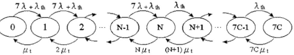
2) Cell-Based Wireless Call Admission Control: From
the cell point of view, we consider a fixed channel assign-ment scheme where a BS reserves a fraction ( ) of total channels as guard channels for handover calls. If the total number of in-progress calls in a cell, denoted as , exceeds , then the BS will accept handover calls only and deny new arrival calls. The state transition of the Markov process for in-progress calls in a cell is shown in Fig. 12. Since the new calls must get through the tree-based admission control, the new call arrival rate is
(11) and the rate of handover calls into a cell is
(12) The effective call arrival rate is given by
Fig. 13. Handover dropping probability versus Erlang load under two-layer and single-layer admission controls.
Fig. 14. Forced termination probability versus Erlang load under two-layer and single-layer admission controls.
Since a busy channel is released with rate , the
effective call departure rate in state is given by
(14)
where . Therefore, we have
(15)
where is the probability of the Markov process in state . Therefore, the steady-state probability in state is derived as follows:
.
(16)
Substituting the above equations into (15), we get
(17) Therefore, we have
(18) From Fig. 12, we get
(19)
can be obtained by assigning an initial value for and iterating (12), (17), and (19) until the value converges [21]. To meet the QoS requirement, the tree-based admission control threshold and cell-based reserved fraction are used to con-trol the handover dropping probability below a predetermined level at all time.
3) Forced Termination Probability: From the user point of
view, another QoS parameter, forced call termination proba-bility ( ), is measured. We define as the probability that an in-progress call makes a successful handover and as the probability of a failure handover. We have [24], [25]
(20) (21) Therefore, [24]
(22)
C. Experimental Results
This section uses an example to illustrate our hierarchical wireless call admission control. We consider a homogeneous system that the call holding time is 10 units of time and the dwelling time of a call in a cell is 2 units of time. Each BS
Fig. 15. Tree-based call blocking probability versus Erlang load at different predeterminedP .
Fig. 16. Tree-based call blocking probability versus forced termination probability at different Erlang loads.
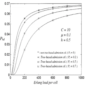
can support up to ten calls. The parameters given above do not affect the relative experimental results shown in the following figures. In Fig. 13, we compare the handover dropping probabil-ities under the two-layer admission control and the single-layer admission control. It shows that as the Erlang load per cell in-creases, the handover dropping probability increases. In addi-tion, the tree-based admission control can effectively reduce the handover dropping probability in comparison with no tree-based admission control ( ). Increasing the new call blocking probability ( ) of the tree-based layer will re-duce the effective new call arrival rate, and thus have a smaller handover dropping probability. Fig. 14 shows the relation be-tween Erlang load per cell and forced termination probability where four different tree-based new call blocking probabilities are considered. It shows that the forced termination probability increases as the Erlang load increases. To guarantee the QoS, controlling the forced termination probability under a prede-fined level is an important criterion. From Fig. 14, adopting
Fig. 17. Total call blocking probability versus Erlang load at different predeterminedP .
Fig. 18. Handover dropping probability versus Erlang load at different handover rates.
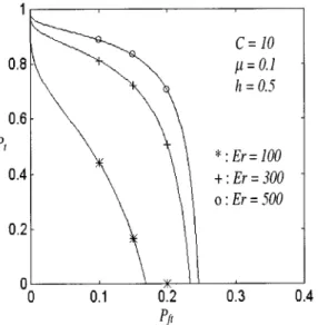
a larger can lower the forced termination probability. The values of that the tree-based admission control should sup-port to meet different requirements is shown in Fig. 15. It shows that a smaller needs a larger to meet the QoS in a heavy traffic load environment. This result can also be validated from Fig. 16. Fig. 17 shows the total call blocking probability of a new call under a given and Erlang load. A new call is more difficult to admit (larger ) in a system where a higher QoS (a smaller ) is requested in a heavy traffic load environment. We now take the effect of handover rates into account. Fig. 18 shows the relation between handover dropping probability and Erlang load at different handover rates. It indicates that an MH has a lower handover dropping probability in a high handover rate environment than in a low one. This is because a higher han-dover rate will have a larger average departure rate in the state transition of the Markov process in Fig. 12; thus, it will have a lower probability in state . Fig. 19 shows that the forced ter-mination probability initially increases up to a threshold, and
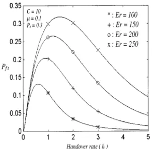
Fig. 19. Forced termination probabilities versus handover rate at different Erlang loads.
then decreases gradually as the handover rate increases. In the ascending curve, the handover dropping probability will not de-crease abruptly due to the inde-crease of the handover rate, while in the descending curve, the forced termination probability will approach zero (but not equal zero) because the handover drop-ping probability will be a small value as the system is in a high handover rate environment.
VI. CONCLUSION
The challenge of the handover problem is closely related to the development of wireless networks. In our proposed approach, under an ATM network backbone, an MH may have high frequent and smooth handover without increasing the workload of network control during the connection lifetime, and it also allows the MH to handover back and forth in a short period of time. Our handover protocol can avoid cell loss and preserve cell sequence. Hence, it can enhance the quality of transmission in real-time traffic such as voice and video. An-other advantage of our protocol is that it can also work correctly in a nonoverlapping microcell environment without any hurdle. This increases network capacity relatively. A formal repre-sentation of the handover protocol using finite-state diagrams has been depicted for protocol specification and verification formally. In addition, a hierarchical wireless call admission control is used to control the handover dropping probability and the forced termination probability below predefined levels to provide a quality-of-service guarantee. Experimental results show that our hierarchical call admission control can provide higher QoS (smaller handover dropping probability and forced termination probability) for admitted MHs in comparison with the single-layer call admission control. With good quality of service for the dense user population, our efficient handover scheme can help to speed up the spread of cellular ATM networks.
ACKNOWLEDGMENT
The authors would like to thank the anonymous reviewers for their valuable comments that improved the quality of this paper.
REFERENCES
[1] R. Cohen, B. Patel, and A. Segall, “Handover in a micro-cell packet switched mobile network,” ACM-Baltzer Wireless Networks, vol. 2, no. 1, pp. 13–25, Mar. 1996.
[2] D. J. Goodman, “Cellular packet communication,” IEEE Trans. Commun., vol. 38, pp. 1272–1280, Aug. 1990.
[3] A. S. Acampora and M. Naghshineh, “An architecture and methodology for mobile-executed handoff in cellular ATM networks,” IEEE J. Select. Areas Commun., vol. 12, pp. 1365–1375, Oct. 1994.
[4] K. S. Meier-Hellstern, G. P. Pollini, and D. J. Goodman, “Network pro-tocols for the cellular packet switch,” IEEE Trans. Commun., vol. 42, pp. 1235–1244, Feb./Mar./April 1994.
[5] B. A. Akyol and D. C. Cox, “Handling mobility in a wireless ATM net-work,” in Proc. IEEE INFOCOM’96, Mar. 1996, pp. 1405–1413. [6] A. S. Acampora and M. Naghshineh, “Control and quality-of-service
provisioning in high-speed microcellular networks,” IEEE Personal Commun., pp. 36–43, 2nd quarter 1994.
[7] J.-Y. Le Boudec, “The asynchronous transfer mode: A tutorial,” Comput. Networks ISDN Syst., vol. 24, pp. 279–308, 1992.
[8] J. Y. Hui, “Resource allocation for broadband networks,” IEEE J. Select. Areas Commun., vol. 6, Dec. 1988.
[9] G. Gallasi, G. Rigolio, and L. Verri, “Resource management and dimen-sioning in ATM networks,” IEEE Network Mag., pp. 8–17, May 1990. [10] B. A. Akyol and D. C. Cox, “Rerouting for handoff in a wireless ATM
network,” IEEE Personal Commun., vol. 3, pp. 26–33, Oct. 1996. [11] R. Ghai and S. Singh, “An architecture and communication protocol
for picocellular networks,” IEEE Personal Commun., vol. 1, pp. 36–46, 1994.
[12] K. Lee, “Supporting mobile multimedia in integrated services net-works,” ACM-Baltzer Wireless Networks, vol. 2, no. 3, pp. 205–217, Aug. 1996.
[13] T.-P. Chu and S. S. Rappaport, “Overlapping coverage with reuse parti-tioning in cellular communication systems,” IEEE Trans. Veh. Technol., vol. 46, pp. 41–54, Feb. 1997.
[14] S. S. Rappaport and L.-R. Hu, “Microcellular communication systems with hierarchical macrocell overlays: Traffic performance models and analysis,” Proc. IEEE, vol. 82, pp. 1383–1387, Sept. 1994.
[15] C. W. Sung and W. S. Wong, “User speed estimation and dynamic channel allocation in hierarchical cellular system,” in Proc. IEEE 44th Veh. Tech. Conf., vol. 1, 1994, pp. 91–95.
[16] K. A. West and G. L. Stilber, “An aggressive dynamic channel as-signment strategy for a microcellular environment,” IEEE Trans. Veh. Technol., vol. 43, Nov. 1994.
[17] M. Naghshineh and A. S. Acampora, “Design and control of micro-cel-lular networks with QoS provisioning for real-time traffic,” in Proc. IEEE Int. Conf. Universal Personal Commun., 1994, pp. 376–381. [18] M. Naghshineh and M. Schwartz, “Distributed call admission control in
mobile/wireless networks,” IEEE J. Select. Areas Commun., vol. 14, pp. 711–717, May 1996.
[19] D. A. Levine, I. F. Akyildiz, and M. Naghshineh, “A resource estimation and call admission algorithm for wireless multimedia networks using the shadow cluster concept,” IEEE/ACM Trans. Networking, vol. 5, pp. 1–12, Feb. 1997.
[20] M. Ferracioli and R. Verdone, “A general methodology based on the handover rate for network planning of cellular radio networks based on ATM,” IEEE J. Select. Areas Commun., vol. 18, pp. 1313–1325, July 2000.
[21] Y.-B. Lin, S. Mohan, and A. Noerpel, “Queueing priority channel as-signment strategies for PCS hand-off and initial access,” IEEE Trans. Veh. Technol., vol. 43, pp. 704–712, Aug. 1994.
[22] L. Kleinrock, Queueing Systems. New York: Wiley Interscience, 1975, vol. 1, Theory.
[23] J. N. Daigle, Queueing Theory for Telecommunications. Reading, MA: Addison-Wesley, 1992.
[24] S. S. Rappaport, “The multiple-call hand-off problem in high-capacity cellular communication systems,” IEEE Trans. Veh. Technol., vol. 40, pp. 546–557, Aug. 1991.
[25] T.-P. Chu and S. S. Rappaport, “Overlapping coverage and channel rearrangement in microcellular communication systems,” Proc. Inst. Elect. Eng. Commun., vol. 142, no. 5, pp. 323–332, Oct. 1995.
He served in the army as a Second Lieutenant Communication Platoon Leader from 1978 to 1980. His research interests include computer networks, mobile computing and wireless Internet, fault-tolerant computing, and mobile agents and e-commerce.