1153
IEEE TRANSACTIONS ON COMMUNICATIONS, VOL. 42, NO. 21314, FEBRUARY/MARCH/APRIL 1994
Design and Analysis
of
a Pipeline Ring
Protocol
P.C. Wong, Senior Member, IEEE, and Tak-Shing Peter
Yum,
Senior Member, IEEEAbstract - A new distributed protocol which supports con- current message transmissions on different ring segments in a ring network is proposed. This protocol allows the destination station to remove the message body from the ring and to issue a new token for the succeeding stations to establish another transmission in the remaining ring segment. This protocol requires only one-bit latency at each station and supports variable size messages. We derived the maximum throughput of the pipeline ring and found it to be
heavily dependent on the message size distribution. The maximum throughput of a single ring for exponential messages and fixed size messages are 1.23 and 1.68 respectively; while for the double ring, the per-ring throughput is 1.7 and 3.25 respectively. Due to analytical complexity, the delay performance is obtained by simu- lation. Two service disciplines are compared. It is found that the Furthest Within Segment (FWS) discipline always performs better than the First Come First Serve (FCFS) discipline. The Short Message Transmission (SMT) scheme is introduced. Under bimodal traffic, it can significantly increase the ring efficiency.
I. INTRODUCTION
Ring networks are very common in local and metropolitan area networks. In particular the Token Ring and the FDDI were developed into the IEEE 802.5 standard [I] and the ANSI X3 standard [2] respectively. The node-to-node connective nature of the ring is particularly suitable for using optical fibres and for supporting concurrent message transmissions on different ring segments. This spatial reuse ability of the ring is used in anumber of single and double ring protocols [3-121. Examples include: 1.
2.
3.
Slotted Rings (e.g. Cambridge Ring [3], Orwell Ring [4])
By allowing the destination to remove the message, the emptied slots can be immediately used by the succeeding stations.
Buffer Insertion Rings (e.g. DLCN [5], DDLCN [ 6 ] ) The ring interface contains a variable length shift register which can buffer incoming messages during the transmission of locally generated messages.
Segmented Rings (e.g. Jafari Loop [7], Leventis Double Loop[8], Circuit-switched Playthrough Rings [9,10], T-S Ring [ 111, Concurrent Transmission Ring (CTRing) [ 121) The ring is logically partitioned into a number of segments, each supports a message transmission. In Jafari loop, when a node wants to communicate with another node, it sends a request message to the controller via a separate control ring. The controller then sends out messages to create a com- munication path between the two nodes on the data ring. Leventis loop is a double ring operating in cycles which are initiated by controller stations. Forward and backward transmissions are limited by the positions of these controller Paper approved by lnder Gopal, the Editor for Network Protocols ofthe IEEE
Corn-unications Society. Makscript received May 8, 1988; revised July 31, 1991. This paper was presented at the IEEE Intemational Conference on Communications, Philadelphia, PA, June 1988.
The authors are with the Department of Information Engineering, The Chinese University of Hong Kong, Shatin, N.T. Hong Kong.
stations. In the playthrough ring, a higher priority preemptive token GO circulates continuously in the ring to collect information and set up new message transmissions on non-overlapping idle ring segments. All message trans- missions are continually interrupted by GO and so the effective transmission time is increased. In the T-S protocol, destination stations are responsible for removing messages from the ring and for initiating new message transmissions by issuing tokens downstream. In order to prevent a new message from colliding with the current transmissions, all current transmissions must finish before the arrival of that new message. This requires long messages to be cut into small units before transmission and the protocol works like a slotted ring. If the message is too small, the destination will not issue any token. Instead, a new token will be released by the source station after the current transmission just like a token ring. These protocols can all achieve a maximum throughput greater than one but on the other hand, they have one or more of the following limitations:
1. 2. 3. 4. 5 . -
Messages have to be cut into smaller units for transmission. This adds overheads in transmission and processing (buffer insertion ring, slotted ring and T-S ring ).
Centralized ring access control by means of a separate ring is needed (Jafari loop).
Each station has to buffer a sufficient number of inbound characters to check the address to determine if the passing message needs to be removed or not. Extra delay (say, 30 bits) is introduced at each station which might affect the ring efficiency if the number of stations is large (buffer insertrings, playthrough ring, Jafari loop and T-S ring).
Message transmission is periodically interrupted by a higher priority control token. The ring interface design is compli- cated and the effective message transmission time is pro- longed (playthrough ring).
Only the double ring structure is supported (Leventis double loop and Jafari loop).
In the following, we describe the pipeline ring protocol [13] which attempts to avoid the above limitations. This protocol performs like an ordinary token ring at light load but gives significantly higher throughput at heavy load by supporting concurrent transmissions on different ring segments. It operates in cycles and provides a fair access to all stations by rotating the
start-up station status among the stations on around-robin basis.
The CTRing is similar to the pipeline ring with the absence of the reset phase. It will be discussed in Section V.
11. PROTOCOL DESCRIPTION
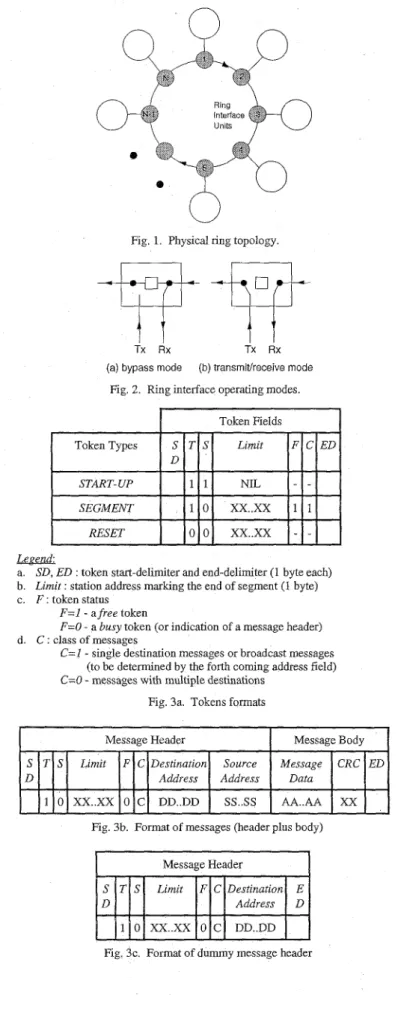
Consider a ring network connecting N stations as shown in figure 1. When the ring is operating, each station can either be in the bypass mode or in the transmidreceive mode (figure 2).
1154 E E E TRANSACTIONS ON COMMUNICATIONS, VOL. 42, NO. 21314, FEBRUARYMARCHIAPRIL 1994 In the bypass mode, each bit arriving at the station is simply
copied out onto the ring. One-bit latency is introduced to the messages passing by. A station in the transmitheceive mode can be transmitting messages, receiving messages, or both.
Units
4 e
L J
Fig. 1. Physical ring topology.
F
Tx R xv
Tx Rx (a) bypass modeFig. 2. Ring interface operating modes.
(b) transmivreceive mode
I
Token FieldsI
La%z.fL
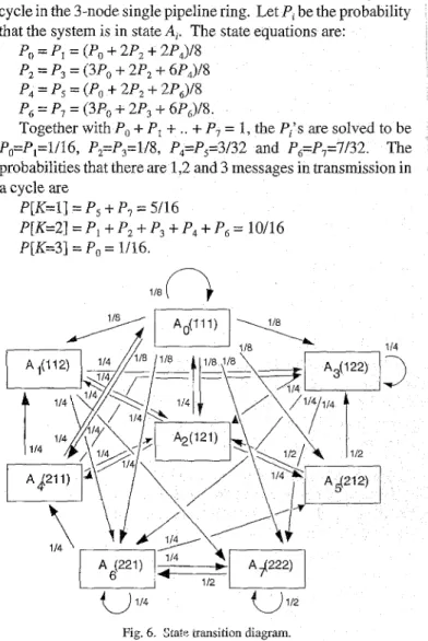
a. SD. ED : token start-delimiter and end-delimiter (1 bvte each) b
c F tokenstatus
Limit station address marking the end of segment (1 byte)
F=l - a free token
F=O - a busy token (or indicat~on of a message header)
C=I - single destinauon messages or broadcast messages (to be deterrmned by the forth cormng address field) C=O - messages with multiple destinations
Fig 3a Tokens formats
d C classofmessages
I
Message HeaderI
MessageBodyI
Fig. 3b. Format of messages (header plus body)
I
Message HeaderI
Fig. 3c. Format of dummy message header
There are three types of control tokens: the START-UP token, the SEGMENT token and the RESET token. Their formats are shown in figure 3a. The Tand the S bits are used to identify the tokens and the messages respectively. The Limit field stores the station address which marks the end of a free segment in the ring. The F bit indicates whether a SEGMENT token is free or not. The Cbit is used to identify messages with multiple destinations.
startup
destination
(a) startup station transmits
+-
first messagedestination
startup
station message remove the sg body
segment token (Iimit=q)
H1 dummy header of msg 1
(b) destination issues a SEGMENT token after the previous header
destination move the
startup
ss body
(c) station 4 seizes the SEGMENT token and transmits its message Message 2
Fig 4 Step-by-step pipeline nng operation.
To illustrate the ring operation, we use an example shown in figure 4. When the ring is idle, a START- UP token circulates in
the ring and all stations are in the bypass mode, i.e., monitoring the ring channel bit by bit. Let station 1 has a message to transmit to station 2. When station 1 detects the START-UP token (i.e. S=l), it changes to the transmitheceive mode and converts the
token into a message header (figure 3b) by setting the S-bit to 0,
Limit field to 1 (its own address), F-bit to 0, C-bit to 0 or 1 depending on the message class and appends the destination address and the source address fields. The message body is then followed. Station 1 assumes the status of the start-up station and starts a busy cycle in the ring.
Succeeding stations relay the message on a bit-by-bit basis if they are not the destination and introduces one bit latency per station. When station 2 (the destination of the message) detects its own address, it changes to the transmitheceive mode and removes the message body from the ring. At the same time, it appends an end-delimiter (ED) to terminate the message header.
WONG AND YUM: DESIGN AND ANALYSIS OF A PIPELINE RING PROTOCOL 1155
This dummy message header will be ignored by all the down- stream stations until it reaches the start-up station and gets absorbed.
The Limit field in the message header is recorded by the destination station. If that station has a message with a desti- nation that is within the free segment limit, it can transmit the message with a new message header attached, following the previous dummy message header. Otherwise, the destination station issues a SEGMENT token downstream to create more transmission segment. In figure 4b, station 2 has no message to transmit, so it issues a SEGMENT token downstream.
Let station
4
has a message to transmit to station 6. When station 4 detects the SEGMENT token and finds that its message falls within the Limit (i.e. station 6 is between station 4 and thestart-up station), it converts the token to a message header and
follows it with the message body. Again, when this message reaches its destination (station 6), another SEGMENT token will be generated and forwarded. This process continues until the
SEGMENT token reaches the start-up station and gets absorbed
together with all the dummy message headers. In figure 4c we show two concurrent message transmissions (1 to 2 and 4 to 6) in this busy cycle.
When the start-up station (station 1) finishes its transmission, it sends out a RESET token (with the Limit field set to its own address). This RESET token is stored and forwarded by the "still transmitting" stations without preemption until it gets back to the
start-up station. After the start-up station absorbs back the RESET token, the ring is idle again. The start-up station then
issues a new START-UP token for the succeeding stations to start a new cycle.
A. Broadcast and Multicast Messages Transmission
When a station wants to broadcast a message, it waits for a
START-UP token, seizes the token and then transmits the
message with the destination address set to 0. All stations will then read the message in the bypass mode without removing the
message body. When a station wants to send a message to a number of destinations, it sets the C-bit to zero and writes all the destination addresses in the message header according to their order in the ring. When aSTART- UP token or aSEGMENTtoken
with sufficient segment size arrives, it seizes the token and transmits the multicast message. The last destination is responsible for removing the message body.
B. Short Messages Transmission (SMT) Scheme
Traffic patterns in LANs are often bimodal, Le. a mixture of short and long packets [14]. When a station has a very short message (say, a few characters) to transmit, the advantage of concurrent message transmissions is less pronounced. An optional SMT scheme can be used to increase the ring efficiency in this case. When a station has a short message, say the transmission time is less than the round-trip propagation delay on the ring, it waits for a START-UP token, seizes the token and transmits the packet with the Limit field set to zero. This setting prohibits the downstream stations from issuing SEGMENT tokens. After the message transmission, a new START-UP token is released immediately to start a new busy cycle. Short message
are hence transmitted in cycles separated from long messages. This scheme provides a fair round-robin assignment of the
start-up station status. Its performance is given in section V. 111. ERROR RECOVERY PROCEDURES
In the IEEE 802.5 token ring, the destination station can send an implicit acknowledgement back to the source station by setting a bit at the end of the message. The message will retum to the source station after around-trip delay and be removed from the ring. In the pipeline ring, errors are handled by the link-level protocols using explicit acknowledgement frames similar to those used in Ethernet. We now describe the recovery procedures for losing tokens and detecting unwarrented tokens:
A. Loss of START-UP token
When a station detects that there is no passage of tokens or messages for a specific time interval, it may conclude that the
START-UP token is lost. It then switches into the transmidre- ceive mode and sends out a RESET token with its own address
stored in the Limit field. When the RESET token returns, the station can issue a new START-UP token downstream. Since a number of stations may issue RESET tokens independently, the
Limit field in each of the received RESET tokens is checked. If the Limit field is larger than the station's own address, the RESET token is discarded. Otherwise, the RESET token is forwarded. In this way, only the station with the smallest address will retrieve its RESET token.
B. Loss of RESET token
After a station issues a RESET token, it starts a timer. If it does not retrieve the issued RESET token within the time-out period, it reissues the RESET token.
C. Loss of SEGMENT token
The loss of SEGMENT token only prohibits possible con- current transmission in a particular cycle. Since the ring is reset after each cycle, no particular recovery procedure is needed.
D. Detection of unwarrented tokens
If there are multiple START-UP andlor multiple SEGMENT tokens with overlapping segment limits in the ring, message transmissions may overlap. To cope with this situation, when a transmitting station receives a message which is not for itself, it terminates its own transmission immediately by appending an End-Delimiter (ED) and issues a RESET token to the ring. If multiple RESET tokens are generated, they are handled as in Case A. If a START-UP or a SEGMENT token is received while a station is transmitting, the token is simply discarded.
IV. THROUGHPUT ANALYSIS
Consider an N-node single ring. To find the maximum throughput, we assume that the ring is under heavy traffic and each station always has a message ready for transmission. We assume that the probability that the message in station i (i=1,2, ...iV) destined for station j (j ;ti) is l/(N-1), independent of
1156 IEEE TRANSACTIONS ON COMMUNICATIONS, VOL 42, NO 21314, FEBRUARYMARCHIAPRIL 1994
of message transmissions in a cycle and T(K) be the length of a K-transmission cycle (see below). In the following, we shall use a 3-node ring to illustrate the analysis.
A. 3-node Single Ring
Fig 5 A 3-node nng network.
Let stations A, B and C in a 3-node ring be arranged as in figure 5 and let the direction of transmission be clockwise. Let
h, be the number of hops required for the message at the start-up station to reach its destination. Similarly, let h, and h, be the
number of hops required for the messages in stations one and two hops away from the start-up station to reach their destina- tions respectively, We denote (h,,hl,h2)=( 1,1,1) as state 0, or A,. At A,, since the hop counts for the messages in all three stations are one, three simultaneous transmissions are possible in the cycle. After the cycle, all three nodes generate new messages with hop counts equal to 1 or 2 with equal probability. Therefore, there are eight possible state transitions from A,, indicated by
{ (h,,hl,h,)ih,,hl,h, E { 1,2}}, each with probability 1/8.
To further illustrate the state transition process, consider A7
with (h,,hl,h,)=(2,2,2). Let station A be the start-up station. In this state, only the transmission by station A is possible. After
ssion is over, station B becomes the new start-up station. But station B has a message with hop count equal to 2 still not transmitted. Therefore h, for the new cycle is 2. Siinilarly, station C has a message with hop count 2; but since station Cis one hop away from the start-up station, h,=2. After the message transmission, station A generates a new message with hop counts 1 or 2 with equal probability and in the new cycle, station A is 2 hops away from the start-up station. Hence
h2=X, where X is equal to 1 or 2 with equal probability. The
transitions of the other states are similar. TABLE 1 : SYSTEM STATES OF THE 3-
I
A , 11 12 12 12Ix
12Ix
ODE PIPELINE RING
I
Table 1 shows the eight possible states, their associated hop counts in the present cycle, the number of simultaneous message transmissions in each state, the possible hop counts of the messages in the next cycle (an X indicates that the entry could be either 1 or 2), the possible states in the next cycle and the transition probability to each of the next states (all equal).
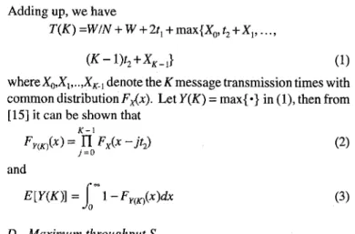
Figure 6 shows all the possible state transitions from cycle to cycle in the 3-node single pipeline ring. Let P, be the probability that the system is in state A,. The state equations are: I
Po = PI = (Po
+
2P2+
2P4)/8Pz = P3 = (3Po
+
2P,+
6P4)/8 P4 = Ps = (Po+
2P2+
2PJ8 P6 = P, = (3Po+
2P3+
6PJ8.Together with Po
+
P,+
..+
P, = 1, the P,'s are solved to be Po=P,=1/16, P2=P,=1/8, P4=P,=3/32 and P6=P,=7/32. The probabilities that there are 1,2 and 3 messages in transmission in a cycle are P[K=l] = P,+
P, = 5/16 P[K=2] = P I+
P,+
P3+
P4+
P,
= 1W16 P[K=3] = Po = 1/16. 118 114 112Fig. 6 . State cransition diagram.
In general, for an N-node ring, the number of states in the Markov chain is (N-l)N. Due to symmetry, only (N-l)@"')
-
1 simultaneous equations need to be solved. Even so, analytical solution beyond N=5 is difficult. We have solved the 3 and 4 node cases and resort to simulation for larger values of N. Aswill be shown in section V, the performance of the pipeline ring is relatively independent of the number of stations in the ring. So the analysis for small number of stations is still useful.
i
B. 3-node Double Ring
In a bidirectional double ring, each station selects the ring with the smaller hop count to transmit its message. The maximum size of each transmission segment is hence reduced from N - l hops to L, = LN/2_1 and L?_ = N - L r ~ i 2 . I - 1 hops for the clockwise and the anti-clockwise sub-rings respectively. As in the single ring case, we assume that the ring is under heavy traffic and each station always has a message ready for transmissioii at
WONG AND YUM: DESIGN AND ANALYSIS OF A PIPELINE RING PROTOCOL 1157
each sub-ring. Let the throughput of the two sub-rings be denoted as S, and S,. Then for the two sub-rings having the same bit rate, the average throughput per ring is (S,+S,)/2.
Consider first the clockwise sub-ring for the 3-node double ring. Here L, =L3/d = 1 and L,=l. Each message therefore requires only one hop to reach its destination. Hence three transmission segments can always be set up. Similarly, the number of simultaneous message transmissions in the anti-clockwise sub-ring is also 3. The average throughput per sub-ring is therefore equal to 3. To solve for the distribution of simultaneous message transmissions per cycle for double rings with four or more nodes, the same technique of enumerating all possible states used in the single ring case can be employed. Again, we limit the analytical computation to N54 and resort to simulation for larger values of N.
C. Cycle Length
Since messages can be of variable sizes, short messages have to wait for long messages to complete before a cycle can end (figure 7). Let r be the ring propagation delay and b be the bit transmission time. Since the protocol introduces one-bit delay at each station, the ring walk time W, defined as the ring propagation delay plus the N-bit station delay, is W=r+Nb. Assuming the N stations are uniformly located on the ring, the walk time from one station to the next is WIN. Let the transmission time of the START-UP and RESETtokens be tl and the transmission time of the SEGMENT tokens be t2. Let the
message transmission time X has a distribution function FAX).
Station 1 releases the STARTUP token
to stad a new cycle STARTUP token
“h
I II
Station Identities RESEl token”1
11 12 \\\\w
1 ’ ‘w+w,N- -
max{%,t;x,3 2 t ; y l ? jFig. 7. A typical cycle showing the tokens and niessages transmission. It can be seen from figure 7 that the length of a cycle with K message transmissions, denoted as T(K), consists of
1. The walk time of a token from the last start-up station to the present start-up station, W/N.
2. The walk time of the token around the ring, W.
3. The total transmission time of the START-UP token and the RESET token, 2t,.
4. The duration of the K simultaneous message transmissions including the staggered SEGMENT token transmission delays ~
Adding up, we have
T(K) =WIN
+
W+
2t1+
max{XD, t2+
X,,. . . ,
(K-l)t,+X,-,I (1)
whereXo,X,,..,XK., denote the Kmessage transmission times with common distribution FAX). Let Y ( K ) = max{ *} in (l), then from
[ 151 it can be shown that
(2) K - 1 j = D FY&) =
n
Fx(x-.&I
and (3) D. Maximum throughput ,,SThe maximum throughput of the pipeline ring
,
,
S
is equal to the ratio of expected amount of message transmissions per cycle to the expected cycle length orN k = l
c
kE[X]P[K=k] (4) s l n a = Nc.
{ W/N+
W+
2t1 + E [Y(k)]} P[K = k] k = lFor fixed size messages of length B, E[X] = B E[Y(k)] = (k
-
l)t2+
B . Hence N k = l B kP[K = k]C
{WIN+
W +2t1 + B + ( k-
l)tJP[K =kI ( 5 ) ’llla= N k = lFor exponentially distributed messages with mean transmission time Up, we have
Denote the second integrand as D,,, we have E[Y(k)] = E[Y(k - l)] + S - D , - , d x
Repeated use of (7) and note that E[Y(1)]= 1/p, we have eventually
1 k - 1
p i = l 0
E[Y(k)] =-+ s m D i d We now expand the Di’s into a series:
1158 IEEE TRANSACTIONS ON COMMUNICATIONS, VOL. 42, NO 21314, FEBRUARY/MARCH/APRIL 1994
The coefficients A,G) are evaluated as follows. Let QJj) = {Qi,Q2, ...} be the set of all j-element subsets of {0,1,2,..,i-l} where Ql,Q2,..,([) in total) are the individual subsets and g, be the sum of all elements in Q,. (Note that Q,’s and g,’s are all functions of j. j Then it can be shown that
n = l
Integrating (9), we have
Substituting (1 1 j back to (8), we have
Substituting (12) into (4j, S,, can be explicitly evaluated. V. RESULTS AND DISCUSSIONS
A. Analytical Results for 4-node Rings
4.0 Analytical results Simulation results
xm
3.0 E (97% C.I.) (I) 3 II 3 .y6
2.0 2 55
.E
1.014 ... -...-.-2
0 0 0 001 0 01 0 1 1 0Normalized propagation delay a
Legend:
o double ring, fixed size messages o double ring, exponential messages n single ring, fixed size messages n single ring, exponential messages A IEEE 802 5 token ring
Fig. 8 Maximum throughput vs normalization delay a on a 4-node ring,
FCFS discipline
In the following discussions, we assume that the expected message size is 16 kbits for both exponential and fixed size messages. The channel data rate is 5 Mbps for each ring and the propagation delay in the cable is 5 psfkm. Figure 8 shows the
maximum throughput S,, of 4-node single and double pipeline rings with different values of normalized propagation delay a where a=rlE[a is defined as the ratio of the round-trip ring delay to the expected message transmission time. The maximum
throughput of a single ring for exponential messages and fixed size messages are 1.23 and 1.68 respectively. In the double ring, each station selects the ring with the smaller hop count to transmit its message. The possibility of concurrent transmissions is therefore increased. The per-ring throughput for exponential and fixed size messages are 1.7 and 3.25 respectively. The total throughput is twice the per-ring throughput, i.e., 3.4 an3 6.5 respectively. The maximum throughput of the pipeline rings I
therefore is always larger than that of the IEEE 802.5 token ring, which is 1. The throughput decreases as a (or the ring size)
increases. The ring throughput with fixed size messages only is larger than that with exponential messages because there i s no need to wait for the longest message to complete transmission beforeanew cyclecan be started. As shown, the analytical results agree very closely with the simulation results.
B. Simulation Results
In the simulation model, we assume that the mean message size is 16 kbits for both exponential an3 fixe3 size messages. The message anivals are assumed to be Poisson. The number ~
of stations is 15. The data rate on each ring is 5 Mbps and the
1
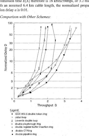
propagation delay in the cable is 5 psfkm. The expectedmessagetransmission time E[XJ therefore is 16 kbits/5Mbps, or 3.2 ms. With an assumed 6.4 km cable length, the normalized propa- gation delay a is 0.01.
1) Comparison with Other Schemes:
’
100 L I 50 30 n 22 20 n x a, -0 ar N % 10E
0 z 5 3 2 1 ‘ I I I I 0 1 2 3 4 Throughput S LegendI IEEE 802 5 double token ring o Jafari loop
A Leventis double loop o double playthrough ring
+ double register buffer insertion ring double CTRing
double pipeline ring
Fig. 9 Delay compansons, double rings, N = 15, a = 0.01, exponentially distributed messages, FCFS discipline
WONG AND YUM: DESIGN AND ANALYSIS OF A PIPELINE RING PROTOCOL 1159
Figure 9 compares the delay performance of pipeline ring, IEEE 802.5 token ring, CTRing, buffer insertion ring, slotted ring, Leventis loop, Jafari loop and playthrough ring. Slotted Ring and T-S ring are not shown for comparison as these rings require data messages to be cut into small units. The message size is exponentially distributed and the destination of a message is uniformly distributed over the ring. The service discipline is First-Come-First-Serve (FCFS). A double ring structure is assumed since it is supported by all protocols. Each station selects the ring with the smaller hop count to transmit its message. The total ring throughput is used for comparison. The results of the Jafari Loop, the playthrough ring and the buffer insertion ring are quoted from [[7], [lo] and [16] respectively. Since other protocols are similar in operation with the pipeline ring, we modified our simulation program and obtained their simulation results under the same set of ring parameters.
As shown, the pipeline ring gives the best overall perform- ance. It has a maximum throughput of about 3.5 (2 times the 1.75 per-ring throughput) and the lowest delay among all the protocols shown up to a throughput of 3.4.
Since the Jafari loop uses only one ring for data transmission, the throughput is definitely lower than that of the other double ring schemes. The maximum throughput is about 1.5 because the number of simultaneous transmissions is limited by the uniform message destination distribution assumed and the FCFS discipline. If we allow the Jafari loop to configure transmissions in different directions, the maximum throughput can be slightly increased to 1.75.
Although the Leventis loop can set up multiple messages transmissions in both rings, the throughput is only around 2, which is similar to that of a double token ring. The throughput is not as high as the double pipeline ring because it needs to wait for the longest message in both "loops" to complete transmission before a new cycle can start. It is therefore better to have independent cycles for each ring (as in the pipeline ring case) so as to reduce the cycle length.
Since there is a continuous interruption of control messages, the delay performance of the playthrough ring at light load is slightly worse than that of the other ring protocols. However, it can achieve a higher maximum throughput of 3.3.
The buffer insertion ring has significantly higher delay than the other rings in light to medium traffic conditions. This delay increases with the number of stations in the ring. It can however achieve a maximum throughput close to 4 at very heavy traffic conditions.
The working principle of the CTRing is similar to that of the pipeline ring and was proposed roughly at the same time. Like the pipeline ring, only the message body is removed and the truncated message header is removed by the original source station. Instead of using special segment tokens, it uses the source and destination addresses in the truncated header to determine the transmission limit and hence can use standard IEEE 802.5 token and message formats. The main difference from the pipelinering is that thereis no reset cycle. When a station finishes its transmission, it will not notify other stations. Instead, it waits in transmitheceive mode until it retrieves its own message header. Therefore if a station receives the dummy headers of
other stations and gets a token, it can only initiate new trans- missions within the calculated transmission limit even if other stations have already finished their transmissions and the entire ring is available for a new cycle of concurrent transmissions. This reduces the possibility of concurrent transmissions and we found from simulation that the total maximum throughput of a double CTRing is only 2.5. As the load increases further beyond the limit, more stations have backlogged messages and the possibility that a transmission can be initiated within a limit is increased. But on the otherhand, the possibility that a new cycle can be restarted for more concurrent transmissions is also reduced. Simulation results in figure 9 show that the throughput is slightyly reduced at heavy loads.
2 ) Number of Stations: 100 50 30 0 20 n x a a, U
-
.-3
10-
mE
Z 5 3 2 1Fixed size messages
(N=l5,50)
...
... ...
... Fix.e.~ .siz.e. .mes.s.a.g.es~
0 0.5 1 1.5 2
Throughput S
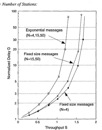
Fig. 10. Delay-throughput characteristics of single pipeline rings, a = 0.01 (N
is the number of stations).
Figure 10 shows the simulation results of the normalized average delay D for three single pipeline rings with 4,15 and 50
nodes respectively. It is seen that the delay is essentially independent of the number of stations for N-4.
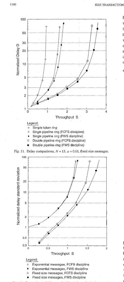
3) Different Service Disciplines:
Figure 11 shows the average delay of a 15-node single ring and a 15-node double ring, both with fixed size messages. The per-ring throughput is shown. Two service disciplines are compared. The First Come First Serve (FCFS) discipline is self-explanatory. The Furthest Within Segment (FWS) discipline selects the message in the station output queue that has the furthest destination within the transmission segment. It is shown that FWS gives higher throughput and lower delay in comparison to FCFS. The maximum throughput values are 1.68 and 1.87 for the single pipeline ring with FCFS and FWS disciplines respectively. The maximum per-ring throughput for the double
1160 100 50 30 n
+
20n
2 10E
x U a N 0 Z 5 3 2 1IEEE TRANSACTIONS ON COMMUNICATIONS, VOL 42, NO 21314, FEBRUARYIMARCWAPRIL 1994
r O 1 2 3 4
Throughput S Legend
+
Simple token ring0 Single pipeline ring (FCFS discipline)
I Single pipeline ring (WS discipline)
0 Double pipeline ring (FCFS discipline)
0 Double pipeline ring (FWS discipline)
Fig 11 Delay compansons, N = 15, a = 0 01, fixed size messages
0 0 5 1 1 5 2
Throughput S Legend:
0 Exponential messages, FCFS discipline
o
e
Exponential messages, FWS discipline Fixed size messages, FCFS discipline Fixed size messages, FWS discipline
Fig. 12. Comparison of delay standard deviations, single ring, N = 15,
a = 0.01
pipeline rings is 3.26 and 3.51 for FCFS and FWS respectively. Figure 12 compares the delay standard deviations of single pipeline rings using the two service disciplines. We found that for both exponentially distributed and fixed size messages, there i s no increase of delay variance using the FWS discipline. In
fact, the delay variance of FWS becomes increasingly smaller when compared to FCFS as the traffic load increases. Therefore, the overall performance of the FWS discipline is always superior than the FCFS discipline in the pipeline ring. From simulation, we found that with the use of tbe FWS discipline, messages to a closer destination are still more readily transmitted than mess- ages to a further destination. There is no forever bloclung of certain messages because the status of start-up station is rotated on a round-robin basis.
4) Bimodal Traffic:
0 0.5 1 1 5
Throughput S Legend:
X Token ring with bimodal traffic A Pipeline ring
0 Pipeline ring with SMT scheme
0 Pipeline ring with long packets only
Fig. 13. Ring performance under bimodal traffic (50% long packets, 50% short packcts).
Figure 13 shows the delay-throughput performance of the pipeline ring with half of the packets 16 kbits long and half of the packets 160 bits long. Other ring parameters are the same as before. The size of the short packets is comparable to the ring round-trip delay. Instead of the normalized delay which depends on the message transmission time, we showed the average waiting time for comparison. We found that the average waiting time of long and short packets are the same under all traffic conditions. The maximum throughput of the pipeline ring under bimodal traffic is 1.25, which is significantly less than the maximum throughput of a pipelinc sing with long packcts only, which is 1.63. Using thc SMT schcme described in section 11,
the maximum throughput can be increased to 1.46. The delay-throughput performance o l the simple token ring is also shown for comparison.
1161
WONG AND YUM: DESIGN AND ANALYSIS OF A PIPELINE RING PROTOCOL
VI. CONCLUSION
In this paper the pipeline ring protocol was proposed and analyzed. This protocol is distributed and can provide a fair access to all stations. Both single and double rings are supported. We found that the ring efficiency is almost independent of the number of stations under symmetrical traffic.
The Furthest Within Segment (FWS) service discipline was proposed for use in the pipeline ring. Its performance was shown to be always better than the traditionally used First Come First Serve (FCFS) discipline. A Short Message Transmission
(SMZ',)
scheme was proposed which can significantly increase the ring efficiency under bimodal traffic conditions. A performance comparison with the IEEE 802.5 token ring, buffer insertion ring, Leventis loop, Jafari loop, CTRing and the playthrough ring was also made.
REFERENCES
[1] Local Area Network Standards: Token-passing ring access methods and physical layer specifications, ANSVIEEE 802.5,1985.
American National Standard, "FDDI Token Ring Media Access Control A. Hopper and R.M.Needham, "The Cambridge Fast Ring Networking System," ZEEE Trans. on Comp., vo1.37, no.lO,Oct.1988, pp.1214-1223.
R.M.Falconer and J.L.Adams, "Orwell: A Protocol for an Integrated Services Local Area Network," British Telecom Technology, October
M.T.Liu and C C.Reames, "Message communication protocol and oper- (MAC)," ANSI X3.139-1987.
1985, pp.27-35.
1.51
ating system design for the distributed loop computer network (DLCN),"
Prdceedings 4th Annual Symp. Computer Architecture, March 1977,
pp. 193-200.
J.J.Wolf and M.T.Liu, "A Distributed Double-Loop Computer Network (DDLCN)," Proceedings of 7th Texas Conf Comp.Syst., Nov.1978,
H.Jafari, T.G.Lewis and J.D.Spragms, "Simulation of a class of ring structured network," IEEE Trans. on Computers, Vo1.C-29, May 1980,
pp.385-392.
SLeventis, G.Papadopoulos and S.Koubias, "A new experimental com- puter network and its simulated performance," Proceedings of INFO- COM'82, Las Vegas, NV, March 1982, pp.113-121.
[6]
pp.6.19-6.34. [7]
[8]
[9] C.B.Silio, Jr., Performance of Multi-Message, Single-Token Rings, Technical Report, ENEE85-05-15, Electrical Engineering Department, University of Maryland, 1985.
[lo] C.B.Silio, Jr., "Performance Approximations for multimessage circuit- switched rings," Proceedings ofZNFOCOM'86, Washington D.C., U.S.A.,
[1 I] G.Pacifici, A.Pattavina, "T-S Protocol: An Access Protocol for Ring Local Area Networks," Proceedings of IEEE GLOBECOM'86, U.S.A., 1986,
pp.25-28.
[12] M.Xu, J.H.Herzog, "Concurrent Token Ring Protocol," Proceedings of
[13] P.C Wong, T.S.Yum, "Design and Analysis of a Pipeline Ring Protocol,"
Proceedings of ICC'88, June 1988, pp.1268-1274.
[14] P.C.Wong, T.S.Yum, "An Integrated Services Token-Controlled Ring Network," IEEE Journal on SelectedAreas in Communications, vo.7, no.5,
June 1989, pp.670-679.
[15] A.Papoulis, Probability, Random Variables, and Stochastic Processes,
McGraw-Hill, 1985.
[16] J.L.Hammand, P.J.P.OReily, Performance Analysis of Local Computer Networks, Addison Wesley, 1986.
March 1986, pp.85-93.
IEEE INFOCOM'88, U.S.A., 1988, pp.145-154.
P.C. Wong (S'82-M'89-SM'93) received his B.Sc, M.Phil. and Ph.D. degrees all from the Chinese University of Hong Kong (CUHK). He returned to CUHK inthe Department of Information Engineeringin 1990. He was avisitingscientist
in IBM T.J,Watson Center, NY in the summer of 1992 and a visiting research professor in the Department of Communication Engineering o f the National Chiao Tung University in 1993. His research interests include fast packet switching, optical networking, network services and applications, and network software engineering.
Tak-Shing Peter Yum (S'76-M78-SM'86) received his BSc, MSc, MPh and PhD from Columbia University in 1974,75,77 and 78 respectively. He worked in Bell Telephone Laboratories, USA for two and a half years and taught in National Chiao Tung University, Taiwan, for 2 years before joining The Chinese University of Hong Kong in 1982. He has published original research on packet switched networks with contributions in routing algorithms, buffer management, deadlock detection algorithms, message resequencing analysis and multiaccess protocols. In recent years, he branched out to work on the design and analysis of cellular network, lightwave networks and video distribution networks. He
believes that the next challenge is designing an intelligent network that can accommodate the needs of individual customers. Peter claims himself to be an existentialist. He enjoys playing bridge and badminton.