DSP-based Robust Controller Design for a Synchronous Reluctance Drive
Ming-Tsan Lin and Tian-Hua LiuDepartment of Electrical Engineering,
National Taiwan University of Science and Technology
Taipei, 106 Taiwan, R. 0. C.
Abstract-This paper presents a systematic robust
controller design for a synchronous reluctance drive
system. This robust controller consists of two parts: a forward-loop
H"
controller to improve the transientresponse, and a load compensator to reduce the load
disturbance. Based on a simplified model of the drive system, the robust control algorithm can be derived. The effect of the parameter variations is studied also. A digital signal processor-TMS C30 is used to implement the control algorithm. All the control loops are executed by
the digital signal processor. The hardware, therefore, is very simple. The drive system performs well. For speed control, the system can be operated even at a low speed as
1 r/min. Several experimental waveforms validate the
theoretical analysis.
I. INTRODUCTION
The synchronous reluctance motor (SRM) has been recognized to have many advantages. For example, its structure is rugged and simple and its efficiency is hgher than the induction mot"? because SRM has no windmg in the rotor. In addition, the SRM does not require any magnetic material. Before ten years ago, the SRM was regarded as mferior to that of the other types of ac machmes due to its lower average torque and larger torque pulsation. Recently, many researchers, however, have proposed many methods to improve the characteristics of the motor as we11 as the drive system [1]-[2]. SRM has been shown to be suitable for ac drive systems. There are many reasons. First, the SRM does
not require to compute the slip as an induction motor does. As
a result, there is no permanent magnetic material parameter sensitivity problem. Next, it does not need any as the permanent magnet synchronous motor does [3]-[4].
Many researchers have applied vector control for the SRMs. However, the advanced control algorithms have not been used in these published papers [1]-[4]. To obtain a hgh performance drive system, the controller design is very
Th~s research is supported by National Science Council under
...
Grant NSC 86-2213-E-011-039.0-7803 -3902-0
important, however, there are only a few papers studled t h ~ s topic. For example, Liu, et al. proposed a fuzzy sliding-mode controller design for a synchronous reluctance drive [5]. The system, however, needs to estimate the acceleration of the motor. Moreover, only a speed-loop controller is designed to acheve both a fast transient response and a good load disturbance rejection. The fuzzy sliding-mode control algorithm, therefore, is very complicated. In th~s paper, a robust control whch consists of a forward-loop
H"
controller and a load compensator is presented. The
H"
is used to improve the transient response of the dnve system, the load compensator, on the other hand, is used to increase the external load disturbance capability. In addition, theH"
controller and the load disturbance can be designed independent because they have different control goals. The design procedures of the robust control are complicated; however, the implementation of the robust control law is very easy. Moreover, the closed-loop SRM drive system performs well by using this proposed control method. For instance, the drive system can be operated at a low speed as 1 rlmin. Basedon the proposed structure, an outer position-loop is easy to be extended. Then, a position control drive system can be obtained. This drive system, therefore, is very flexible. To the best of the authors' knowledge, this is a new control algorithm for the SRM dnve system.
11. MATHEMATICAL MODEL
A. Motor and Load Dynamics
The mathematical model of a synchronous reluctance motor without a damping winding can be described, in the synchronous
d e
- q e
reference fiame, by the following nonlinear differential equations:P id, = ( 'ds -'s id, + Lqs iqs Lds (1)
P
iqs
= (v,,
-
5
i,
-
U ,L,
ids 1L ,
(2)where p is the differential operator ddt,
i,
andiqs
areq e
axis stator voltages,r,
is the stator resistance, U , is the angular synchronous speed,Lds
andL,,
are thed e
-
q
eaxis stator inductances. The electro-magnetic torque of the motor is
2 P
(3)
where
Po
is the number of poles of the motor. The speed of the motor is(4)
J
where J is the inertia constant of the motor and load,
I;
is the external load torque, B is the viscous frictional coefficient of the motor and load.B. Simplified Model
In this paper, a voltage-source, current-regulated inverter which is based on three-phase independent current control is used. The current control is executed by the DSP with 50 ps
sampling interval. The switchmg fi-equency of the inverter, therefore, is 20 kHz. Then, the three phase currents i , , i , ,
i , can follow the three-phase current commands
i,
, l b s ,i:,.
After the coordinate transformation fi-om the a-b-c stationery fi-ame to thed e
- q e
synchronous fi-ame, we can obtain that thed e
-
q e
axis currentsi,
andi,,
follow thed e
- q e
axis current commands very well. The torque equation (3), therefore, can be expressed as* .*
( 5 )
According to equation
(9,
we can determine the torque of the motor by adjusting the d-q axis current commands. If we maintainids =
*i,,
* , then the torque<
is proportional to' 2
i , and a maximum torque control is achieved.
Although this maximum torque control has larger torque/ampere ratio, this simplified plant, however, is a nonlinear system. The speed-loop controller, therefore, is difficult to design. If we maintain ,;z as a constant, the torque is hnearly proportional to the q-axis current. This is a field oriented control. The speed of the motor can be easily controlled by adjusting the torque.of the motor. As a result, we can easily design the speed-loop controller under field oriented control. In this paper, we focus only on the field oriented control because it is more suitable for a high
performance dnve system.
111. CONTROL ALGORITHM
A. The Closed-loop Control System
The proposed closed-loop control system is shown in Fig 1. The system consists of a simplified plant and a robust control law whch is implemented by a DSP. A PI controller
has been widely used in a forward-loop of the speed control drive system. The P controller is used to improve the transient response. The I controller is used to reduce the steady-state error. However, using only a PI controller can not obtain both a fast transient response and a good load disturbance rejection capability for a drive system. The major reason is that the PI controller belongs to a one-degree-of-fieedom controller and can not control both transient response and load disturbance very well at only one set parameters of the PI controller. In addition, the selection of the parameters of the PI controller needs trial and error. Hori , et al. proposed using a forward- loop PI controller with a load compensator for a dc dnve system [6]. Thls control algorithm can perform better than a simple PI control. The major reason is that in this paper, the forward-loop PI controller is used to adjust the transient response, and the load compensator is used to compensate the speed dip as the external load is added. a s control algorithm, therefore, belongs to a two-degree-of-fieedom controller. These papers, however, still require a PI controller as a forward-loop controller. The
H"
controller has been shown to perform better than a PI controller because its parameters is determined by using optimization techmque. In this paper, we propose a new method by using both theH"
controller and the load compensator to control a SRM drive system. The simulation and experimental results show that the system performs very well.
In addition, the parameters of theH"
controller can be systematically determined. The detailed design procedures and the closed-loop system analysis are shown as follows. r - - - - - - - - - - S np1,f e l Yodel T i = - -1 - - - ? "J_
w
d
y
p
s
+
~~ .i 1.I_
- I rnntroiier,
J s + B IFig. 1 Block diagram of the system.
4
where
p
is a tuning factor,p
is a selected dc gain, andx
is a B. The Forward-loop Controller DesignA
H"
controller is designed for the forward-loop controller. The design objective of theH"
controller is to minimize the form( 6 ) where V and W are suitably chosen weighting functions, which are based on the designer's choice. S is the sensitivity h c t i o n , and T is its complement. In this paper, paper, the wei&ting functions V and W are selected, respectively, as
Sup[lV(iw)
S ( i W )I
+IW(iW) T ( i W )I
'
10
( 7 )
and
W(s>= ( (8)
The
H"
controller can be calculated. The parameters of theH"
controller are related to the parameters of the simplified plant and the weightjngs. First, define a tuning factor p=(a,
/a ,
) . The weighting function V is used here to reflect the information about the transient response and the load attenuation. The weighting function W, on the other hand, is used here to reflect the dormation about the input energy of the plant. Generally speaking, the value of p is selected as a small value (e.g. 0.001), in order to obtain a fast response and good load attenuation. The energy of the control input is less importantthan
the performance for a dnve system. Then, we can compute a pseudo parameterx
according to the following nonlinear equation:(9)
Finally, the speed-loop
H"
controller is related to the measured parameters of the motor and the parametersp
,p
andx
.
It can be expressed asJ,s
+
B,
K,S2
pseudo parameter
C. The Load Compensator Design
A load compensator, which includes an external load estimator and a current command compensator, is shown in Fig. 1. First, the load estimator is used to estimate the external load. This estimator uses the q-axis current, speed, and acceleration to determine the external load. Their relationship
is described as follows: A
T
=K -
T,
I
=K,
Awhere
T
is the estimated external load. In the real world, the estimated external load consists of a lot of noises which causes by the speed sensor and the derivation of the speed. A low pass filter, Q(s), therefore, is designed to reduce these high &equency noises. Then, we can easily compute the compensating current command as:I?
A 1
where A i q * (s) is the compensating current command, Q(s) is the transfer function of the low pass lilter. Theoretically, by using the above method, we can exactly compensate the speed dip whde the external load is added. In the real world, however, there are some problems. First, the parameters of the plant can not be precisely measured. There are some differences between the measured parameters and their true values. Next, the parameters of the plant may be changed at a different environment. In addition, the low pass filter causes
lag between
T
and Aiq * . Although the load compensator can not perfectly compensate the effect of the external load, it stdl can effectively reduce the speed dip of the dnve system. In this paper, we select Q(s)=1/(1+2, s), where2, is the inverse of the bandwidth of the low pass filter. The q-axis current command isA
1
the q-axis current command.
IV. EXPERIMENTAL RESULTS
Some simulated and experimental results are shown here. The tuning parameters are selected as: pO.001, p=lO, Zc=O.OO1. Fig. 2 shows the speed responses of the drive
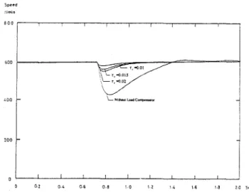
system at 600 rlmin. Selecting a small p can obtain a faster response. Fig. 3 shows the load disturbance responses of an external load 6 Nt. m. According to this figure, a small 7,
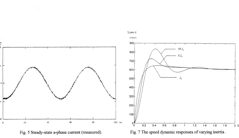
can obtain a better load disturbance response. In the real world, however, the Z, can not be too small because a small Zc causes a lot of harmonics in the signal of the estimated torque. Fig. 4 shows the a-phase current at 1 rlmin. The figure shows the SRh4 drive system can be operated at a low speed. The speed response is not shown here because of the 1 rlmin signal is too weak to be measured by a storage scope. Fig. 5 shows the steady-state a-phase measured current waveforms. The waveforms are obtained at 600 rlnlin with 6 Nt-m external load. Fig. 6 shows the measured pulse width modulated voltage waveforms of the line voltage,
.
The switching frequency is about 20 kHz. Fig. 7 shows the dynamic responses when the inertia of the external load is varied. Although the controller is designed under the measured parameterJ,,
, the closed-loop system performs well even the inertia is changed fromJ,,
to 5J,,
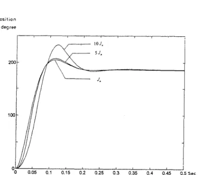
. Fig. 8 shows the measured position response. Fig. 9 shows the closed-loop dynamic position responses when the inertia of the load is changed.Speed rim," BOO I ,
I
0 I , I 1 , I o 0 2 0 4 1. 0 3 o z L , a 7 , secFig. 2 The speed responses at 600 rlmin (measured).
I
0 ' I I I I I -
-0 0.2 0.L 0 6 0-8 1 0 1 2 1 1 1.6 I 8 2 0 5 ~ Fig. 3 The load disturbance responses (measured).
Fig. 4 The a-phase current at 1 rlmin (measured).
I I I I
O 10 a 60 a0 100 711
Fig. 5 Steady-state a-phase current (measured).
"ob
I I
-100
'
I I I0 20 '0 6 0 ea im l l s
Fig. 6 Steady-state h e voltage
t,
(measured).J. 400 800 700 600 500 400 300 200 100 0 0 0 2 0 4 0 6 0 8 1 1 2 1 4 1 6 1 8 2 % I 4
i
Fig. 7 The speed dynamic responses of varying inertia
Position degree 20 0 100 0 I 0 100 200 300 400 500 m s
VI. ACKNOWLEDGMENT
Posit i o n
degree
‘
A
0.05 0.1 0.15 0.2 0.25 0.3 0.35 0.4 0.45 0.5 Sec
Fig. 9 The position dynamic responses of varying inertia
.
V. CONCLUSIONS
In this paper, the design and implementation of applymg robust control for a DSP-based synchronous reluctance drive system has been investigated. A systematic and analyt~c approach of designing this robust controller is presented. A fully digital with multi-rate drive system is proposed. The proposed theoretical modeling and design approach has been validated by the measured waveforms. Although the control algorithm is very simple for the DSP, the drive system performs well. The proposed system is flexible because the control algorithm is executed by using a DSP. Other advanced
control algorithms can be developed in this proposed control structure. The results presented in this paper represent a new direction of designing an advanced robust control algorithm for a synchronous reluctance drive.
This research was supported by the National Science Council of the Republic of China under grant NSC 86-2213- E-0 1 1-039.
REFERENCES
L. Xu, T. A. Lipo, andD. W. Novotny, “Vector control of a synchronous reluctance motor including saturation and iron loss,” IEEE Trans. on Ind. Appl., vol.. 27, no. 5, Sep.1 Oct.
1991, pp. 977-985.
L. Xu, and J. A. Yao, “Compensated vector control scheme of a synchronous reluctance motor including saturation and iron losses,” IEEE Trans. on Ind. Appl., vol. 28, no. 6, Nov./ Dec.
1 9 9 2 , ~ ~ . 1330-1338.
B. K. Bose, “Technology trends in microcomputer control of electrical machines,” IEEE Trans. on Ind. Electron., vol. 35, no. 1, Feb. 1988, pp. 160-
177.
T. A. Lipo, “Recent progress in the development of solid-state ac motor drives,” IEEE Trans. on Power Electron., vol. 3, no. 2 ,Apr. 1988, pp. 105-
117.
T. H. Liu, and M. T. Lin, “A f i z z y slidmg-mode controller design for
a
synchronous reluctance motor dnve,” IEEE Trans. on Aero. and Electron. Syst., vol. 32, no. 3, July 1996, pp. 1065-1076.T. Umeno, and Y. Hori, “Robust speed control of DC servomotors using modern two degees-of- fieedom controller design.,” IEEE Trans. on Ind. Electron., vol.. 38, no. 5 , Oct. 1991, pp. 363-368.