Study on a practical use of the suction
method for reservoir sustainability and
downstream conservation in Japan
M. Miyakawa, T. Miyawaki, S. Nakanishi and T. Ishigami
Abstract
In Japan, reservoir sedimentation is one of the most critical issues encountered in the field of reservoir sustainability and downstream river environment conservation. Though the conditions where sediment countermeasure methods can be effectively employed are limited, and it is difficult to control the quantity and quality of the discharged sediment by only applying a single method, appropriate sediment management must be implemented. In this study, we report on the effectiveness of the suction method as a dam sediment countermeasure by recent experimental results. Based on the results of this study, we suggest there is a need to examine and design an optimal countermeasure approach that combines practical methods and the suction method based on dam characteristics on a case-by-case basis to appropriately manage sediment, thereby ensuring reservoir sustainability and downstream river environment conservation.
Keywords: suction method, sediment management, reservoir sediment countermeasure.
1. Introduction
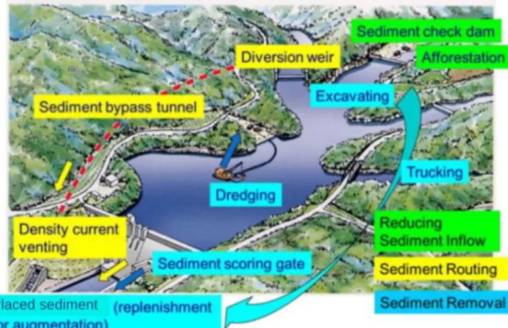
The construction of a dam can interrupt the movement of sediment through a river system. Decreased downstream sediment causes environmental complications related to the riverbed such as degradation, armoring, and fewer opportunities to renew the riverbed material. Furthermore, sedimentation causes a reduction in reservoir storage capacity; thus, reservoir sedimentation is one of the most critical issues encountered regarding reservoir sustainability and downstream river environmental conservation in Japan. Furthermore, according to Sakamoto.et al. (2018), sediment yields of Japanese rivers are often relatively high because of topographical, geological, and hydrological conditions, thereby causing sedimentation problems in several reservoirs. A number of studies have been conducted to evaluate the countermeasure methods to address sedimentation issues. The countermeasure methods for suitable sediment management include the following three primary approaches: (1) reducing sediment inflow using various measures such as the use of check dams; (2) routing sediment inflow using various measures, including the use bypass tunnels; and (3) eliminating accumulated sediments using various measures, such as excavation and dredging (Figure 1). Thus far, sediment flushing (via a sediment scoring gate) with water level drawdown and sediment bypassing methods have been developed and employed in Japan along with traditional measures, including excavation
and dredging. However, the conditions required for the application of these countermeasure methods are restricted, and when considering reservoir sustainability and downstream river environment conservation, it is difficult to control the quantity and quality of the discharged sediment using only one method. Furthermore, in Japan, it is also necessary to implement appropriate sediment management efforts to avoid burying reservoirs and river channels, as well as preventing the discharge of turbid water under non-flood conditions.
2.
The burrowing-type sediment removal suction pipe method
Recently, the suction method has been developed as a new sediment supply measure that uses the differential water head between the upstream and downstream river areas of a dam. This method has become a practical application around the world, and from past research and cases studies, we classify three types of the suction method: (1) fixed type, such as a sedicon sulicer and vertical, multi-holed double-pipe system; (2) mobile type, such as a sedicon dredger and siphon system; and (3) semi-fixed type (surface installation type), such as the burrowing-type sediment removal suction pipe method.
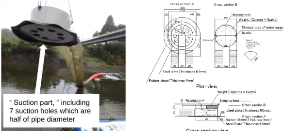
We have been working to develop the burrowing-type sediment removal suction pipe method and have set the following objectives to ensure the development and applicability for Japan’s specific needs, including: (1) a change in reservoir operation is not required; (2) the sediment discharge rate can be controlled based on the water discharge rate; (3) the size of the facility is small, and it is economic, easy to construct, and mobile; and (4) it can be operated safely under flood conditions. Figure 2 depicts a 300-mm diameter burrowing-type sediment removal suction pipe which is the largest size now. It is shaped like a bent pipe with a water intake at the upstream end of the flexible pipe and an outlet at the downstream end of the flexible pipe. The U-bent portion comprises steel and an impermeable sheet. Furthermore, the sediment suction holes are installed at the U-bent section and upstream portions of the pipe. Figure 3 depicts the sediment discharge process for the burrowing-type sediment removal suction pipe. The pipe was initially set on the surface of the deposited sediment under non-flood conditions. When the valve was
Figure 1. Practical sediment countermeasure methods in Japan (partially modified Sakamoto.(2018))
opened at the beginning of the discharge process under flood conditions, the pipe was expected to suck up the sediments through the sediment suction holes in the bent part and gradually burrow into the sediment using the energy of the differential water head. Several laboratory and field experiments were used to confirm that the pipe could be discharged to non-cohesive debris-less sediment materials.
3.
The burrowing-type method’s performance
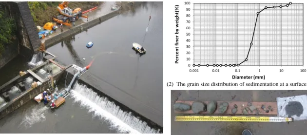
We demonstrated the 300-mm diameter pipe’s performance based on the results of recent laboratory and field experiments. Figure 4 depicts the field experiments and results. Figure 4(1) shows the field experiment setup in experimental condition with about 1.6 m of water head difference and an approximately 20-m long pipe, and Figure 4(2) shows the grain size distribution of sedimentation at the surface. Figure 4(3) shows a sample of discharged sedimentation, with experimental results indicating it can be discharged a maximum 150-mm sediment as same as a suction hole diameter. Figure 5 shows the laboratory experimental situation and results. Figure 5(1) shows the experimental setup with about 2.4 m of water head difference and an approximately 20-m long pipe, while Figure 5(2) shows the grain size distribution of the sediment. Figure 5(3) shows the
time-“ Suction part, time-“ including 7 suction holes which are half of pipe diameter
Figure 2. The 300mm diameter of the burrowing-type sediment removal suction pipe & suction part
series relationship between sediment concentration and suction part depth, which confirmed that the sediment concentration rose to about 10% as the suction part was submerged. Figure 5(4) shows the time-series relationship between sediment concentration and pipe velocity, which indicated that the sediment concentration increased, and the flow velocity in the pipe decreased. When a volume of removed sediment was obtained by a surveying sedimentation surface shape before and after sediment discharge, it was confirmed it can be discharged at a rate of about 50 m3/h of sedimentation. For larger reservoirs, further increases in this rate are expected. As a result of these experiments, this method is expected to be implemented as a practical method at dams. Now, research regarding suction efficiency and the facility placement is being conducted regarding certain unexplained conditions, such as the water head difference,
0 10 20 30 40 50 60 70 80 90 100 0.001 0.01 0.1 1 10 100 P e rc e nt fine r by w e ight (%) Diameter (mm)
Figure 4. The 300-mm diameter pipe’s field experiment results(quoted from Miyakawa et al.(2015))
(3) A sample of discharged sedimentation (2) The grain size distribution of sedimentation at a surface
(1) The field experiment setup at the check dam
0.0 1.0 2.0 3.0 4.0 5.0 0 5 10 15 20 25 0.0 0.5 1.0 1.5 2.0 Pipe V elocit y (m/ s) Sedimen t Conc en tr at ion (%) Time (hr) Sediment Concentration Pipe Velocity 0.0 0.5 1.0 1.5 2.0 2.5 0 5 10 15 20 25 0.0 0.5 1.0 1.5 2.0 Suct ion P ar t Dept h (m) Sedimen t Concen tr ati on (% ) Time (hr) Sediment Concentration Suction Part Depth
Figure 5. The 300-mm diameter pipe’s laboratory experiment results
0 10 20 30 40 50 60 70 80 90 100 0.001 0.01 0.1 1 10 100
Percent finer by weight
(%)
Diameter (mm)
(2) The grain size distribution of sediment (1) The laboratory experimental setup
(3) The time series of relation between sediment
pipe length, sediment particle diameter, and the relationship between the flow velocity inside the pipe and the sediment concentration.
4.
Development a preprocessing method
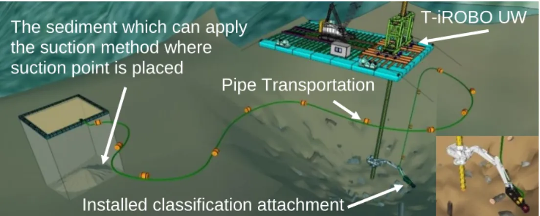
A reservoir not only captures water and sediment, but also debris, driftwood, and other such obstructions. If the suction method is applied to sedimentation including obstructions, these can prevent the suction from functioning properly. Consequently, we propose a preprocessing method to eliminate the debris, driftwood, and other such obstacles at various depths of the reservoir. Figure 6 shows an image of preprocessing dredging method that can be used to until a depth of 50 m by employing T-iROBO UW (i.e., the underwater method of working the relies on shaft-style equipment) with a sediment classification attachment. In particular, an attachment with a pump and a screen can be used to classify the sediment and eliminate obstructions into the pipe. The sediment is transported from the suction point via a pipeline, and at the end of the pipe, the sediment is discharged to the downstream destination. This method is currently under development by Taisei Co., Ltd. as part of the joint research efforts. Our primary objective is to employ the suction method in conjunction with this preprocessing method at a dam.
5.
Considering the sustainable sediment countermeasure
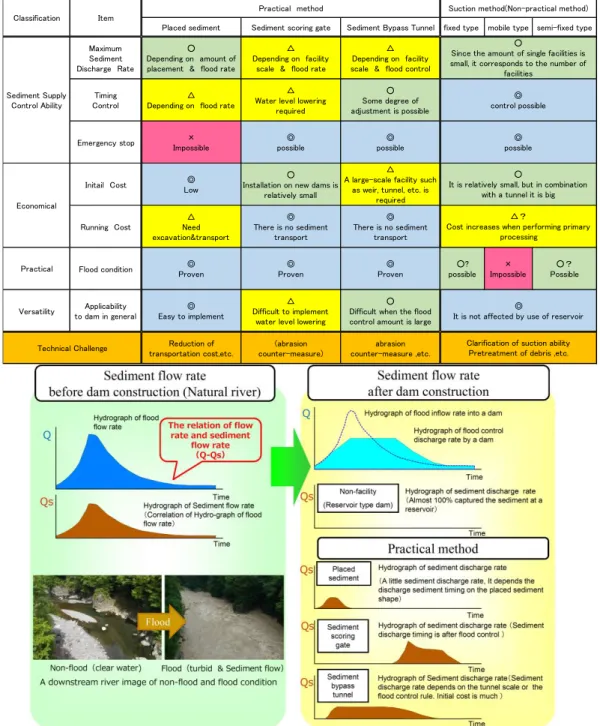
Table 1 summarizes the characteristics and challenges of sedimentation countermeasure methods (i.e., sediment supply countermeasures) in Japan. There are advantages and disadvantages and technical challenges to be further resolved for each sediment countermeasure method. The relationship between Q and Qs (flow rate and sediment flow rate) characteristics before and after dam construction is shown in Figure 7 based on a general case of method application. Before constructing a dam, the sediment flow rate is determined based on the flood flow rate. For this reason, after the dam construction, the ideal sediment discharge rate is considered to be decided according to the flow rate after the flood control rate from the dam to the downstream river channels. Based on the information provided in Table 1 and Figure 7, when a general case is considered and only one method is selected, the sediment bypass tunnel is likely to be the optimal option.
The sediment which can apply the suction method where suction point is placed
Pipe Transportation
Installed classification attachment
Figure 6. An image of a preprocessing dredging method (cooperated with Taisei Co., Ltd.)
However, bypass tunnels exhibit various sediment discharge characteristics that depend on the tunnel scale and water level; therefore, a bypass tunnel is not always the most suitable solution for every downstream river environment. Whereas, Figure 8 shows the relationship between Q and Qs characteristics of the suction method at a flood condition. Based on the information provided in Table 1 and Figure 8, the suction method may be able to control the maximum discharge rate and incorporate various timing of discharges, providing a degree of flexibility. Since it is crucial to avoid burying reservoirs and river channels, as well as prevent the discharge of turbid water during non-flood conditions, in
Table 1. Characteristics and challenges of sediment countermeasure methods in Japan
Placed sediment Sediment scoring gate Sediment Bypass Tunnel fixed type mobile type semi-fixed type Maximum Sediment Discharge Rate ○ Depending on amount of placement & flood rate △ Depending on facility scale & flood rate △ Depending on facility scale & flood control Timing Control △ Depending on flood rate
△ Water level lowering
required
○ Some degree of adjustment is possible Emergency stop Impossible× possible◎ possible◎
Initail Cost Low◎
○ Installation on new dams is
relatively small
△ A large-scale facility such
as weir, tunnel, etc. is required Running Cost △ Need excavation&transport ◎ There is no sediment transport ◎ There is no sediment transport
Flood condition Proven◎ Proven◎ Proven◎ possible○? Impossible× Possible○?
Versatility to dam in generalApplicability Easy to implement◎
△ Difficult to implement
water level lowering
○ Difficult when the flood control amount is large Reduction of transportation cost,etc. (abrasion counter-measure) abrasion counter-measure ,etc.
Technical Challenge Clarification of suction abilityPretreatment of debris ,etc. ○
Since the amount of single facilities is small, it corresponds to the number of
facilities ◎ control possible ◎ possible ◎
It is not affected by use of reservoir ○
It is relatively small, but in combination with a tunnel it is big
△?
Cost increases when performing primary processing
Practical Economical
Suction method(Non-practical method) Practical method
Classification Item
Sediment Supply Control Ability
Japan, the optimal sediment discharge countermeasure design and configuration may be a combination of a sediment bypass tunnel and a semi-fixed type suction method. In particular, it is necessary to examine to a plurality of countermeasure methods in accordance with the characteristics of each dam on a case-by-case basis.
6.
Conclusions
In this study, we confirmed that a 300-mm diameter burrowing-type sediment removal suction pipe can discharge at about 50 m3/h and a 150-mm diameter sediment through the experiments. This is expected to be implemented as a practical method. In addition, we propose a preprocessing method to classify obstructions to ensure that the suction method can be practically applied. Finally, we suggest the need to examine the adequately design an optimal solution that includes a combination of countermeasure methods including the suction method in Japan. Whereas, the best solution should be considered according to the characteristics of the dam to ensure appropriate sediment management as close as possible to the natural sediment flow conditions before dam construction, thereby ensuring reservoir sustainability and downstream river environment conservation.
Acknowledgement
We are deeply grateful to the Takataki dam administration office of Chiba prefecture and the National Institute for Land and Infrastructure Management of MLIT for their help with our experiment. We are also deeply grateful to Mr. Kusumi, M., Mr. Kimura, M., Mr. Arai, H., & Mr. Sano, K. for their help with our preprocessing method research.
References
Aspen, B., Stokseth, S., Jacobsen, T. (2015): Installation of 1200 mm casing pipe under Bajna Dam in Albania,for high capacity hydrosuction dredging, Twenty-fifth International Congress on Large
Dams, Question 99, R.24:pp.318–330, International Commission on Large Dams, Stavarnger,
Norway.
Ishigami, T.(2019): Technical view of sediment control measures of dams, Dam Engineering, No.389,pp.15–20. (in Japanese)
Hisano, A., Ota, S., Maeda, K. (2016): Vertical multi-holed double-pipe system: A new sediment suction method utilizing a natural head, 4th Asia-Pacific Group Symposium and 9th East Asian Area Dam
Conference, pp.2-25-2-30, Asia-Pacific Group International Commission on Large Dams,
Sapporo, Japan.
Jacobsen, T. (2014). Sediment removal in South America, International Water Power & Dam Construction, Website: https://www.waterpowermagazine.com/features/featuresouth-american-sediments-4398226/
Jacobsen, T. (2018): Maintaining reservoir volume by combining hydrosuction dredging and bypass tunnels, Twenty-sixth International Congress on Large Dams, Question 100, R.7:pp.93–105, International Commission on Large Dams, Vienne, Austria.
Jimenez, A., Figueroa, R., Jacobsen, T. (2015): Dredging of cohesive sediments with sedicon dredge in El Canada hydropower plant in Guatemala, Twenty-fifth International Congress on Large Dams, Question 99, R.26:pp.349–361, International Commission on Large Dams, Stavarnger, Norway. Miyakawa, M., Hakoishi, N.,& Sakurai, T. (2014): Development of the sediment removal suction pipe by laboratory and field experiments, International Symposium on Dams for A Changing World, No.186, International Commission on Large Dams, Bali, Indonesia.
Miyakawa, M., et al.(2015): Examination for practical use by the field experiment of the sediment removal suction pipe, Advances in river engineering, No.21,pp.189–194.(in Japanese)
Miyakawa, M., Motoyama, K., Kusumi, M.&Kimura, M. (2017): Study on the pretreatment method of debris for the application of the suction method (the burrowing-type sediment removal suction pipe), 72th JSCE Annual Meeting, Ⅵ-852, pp.1703–1704. (in Japanese)
New paradigms on sediment management for reservoir and river basin sustainability in Japan,
Hydropower & Dams, 2, pp.66–72.
Sakurai, T. & Hakoishi, N. (2012): Hydraulic characteristics of the burrowing type sediment removal suction pipe, International Symposium on Dams for A Changing World, No.281, International Commission on Large Dams, Kyoto, Japan.
Sakurai, T. (2014): How far advance the sediment supply countermeasure?, The proceedings of river research seminar in 2014.,pp.130–142. (in Japanese)
Sano, K., Kimura, M., Arai, H., Kusumi, M. Miyakawa, M., Motoyama, K. (2018): The development of cutting attachment of driftwood with underwater working machine, 73th JSCE Annual Meeting, Ⅱ-077, pp.153–154. (in Japanese)
Sumi, T., Itoh, H., Sase, T., Satoh, T., Kantoush, S. (2017): Sediments discharging using siphon system demonstration test at the Republic of Indonesia Wonogiri multipurpose dam, International
Symposium on Dams for A Changing World, No.82, International Commission on Large Dams,
Prague, Czech Republic.
Authors
M. Miyakawa (corresponding author) T. Miyawaki
S. Nakanishi T. Ishigami
Public Works Research Institute (PWRI), Japan Email: [email protected]