A Location-based 3-tier Multimedia Transmission Platform over Mobile Wireless Networks
7
0
0
全文
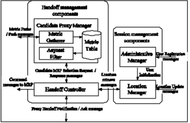
(2) and video transmission are suitable to use the 3-tier networking architecture to achieve fast and scalable services [2]. In the 3-tier networking architecture, proxies are located at suitable places for load balance and scalability concerns. The 3-tier networking architecture inevitably should be applied to the mobile Internet for the same concerns that exist in the wired Internet. However, when a mobile host, which is served in the 3-tier networking architecture, moves far away from the currently used proxy P, it is hard and unreasonable that the mobile host still should receive packets from proxy P. One reasonable solution is that proxies should dynamically serve mobile hosts according to geographical dependency and the network situation. Under the above concerns, the 3rd handoff type at the application layer called "proxy handoff" or "`layer 7 handoff"' should be adopted. The goal of proxy handoff is to allow a mobile host still can receive packets from the corresponding server when its served proxy is switched from the currently used one to the other one.. (MSCs), in which each MSC contains one mobile handoff server (MHS) and one or more media servers (MS). The proxy level contains a number of mobile regional proxy (MRP) servers and access point manager (APM) servers. The client level contains a number of mobile hosts (MH) and wireless access points (AP).. Figure 1: The abstract system architecture of Mobile Multimedia Transmission Platform (MMTP).. To resolve handoff control in the 3-tier networking architecture over the wireless mobile Internet, we propose a 3-tier multimedia mobile transmission platform (MMTP) in the IPv6-based wireless mobile network. MMTP provides means of AP, IP, and proxy handoff operations and keeps the media service session in progress when the mobile host does AP handoff, IP handoff, and/or proxy handoff. For proxy handoff, we propose a scheme based on the anycasting technique. When a mobile host needs to do proxy handoff, some proxy servers are selected as the candidate proxy servers to form an anycast group according to the selection policy. The selection policy essentially takes load balance, transmission delay, and scalability into consideration. Then, a proxy server will be selected from the anycast group. To have smooth handoff, the media server transmits packets to candidate proxy servers using multicast before the proxy handoff is executed. In this way, candidate proxy servers can cache a certain amount of packets before it servers the corresponding mobile host.. 2.1. The Server Level The server level contains a number of mobile server clusters. A mobile server cluster contains a mobile handoff server (MHS) and a number of media servers (MSs). Since an MS is the regular media-streaming server, we focus on MHS. Two sets of components in MHS are session management components and handoff management components. Figure 2 is the functional block diagram for the internal architecture of MHS.. The remaining part of this paper is organized follows. Section 2 presents the system architecture of MMTP. Section 3 introduces handoff operations. Section 4 has performance analysis. Finally, conclusion remarks are given in Section 5.. Figure 2: The functional block of the mobile handoff server (MHS).. 2. MMTP System Architecture Session management components are in charge of managing each MH's service session and maintaining each MH's location information in order to provide mobility support. Session management components contain Administrative Manager and Location Manager.. The Mobile Multimedia Transmission Platform (MMTP) that we proposed in this paper is a 3-tier based multimedia system architecture. Three levels that MMTP contains are (1) server level, (2) proxy level, and (3) client level. Figure 1 depicts the abstract system architecture of MMTP. The server level contains a number of mobile server clusters. l. -2-. Administrative Manager.
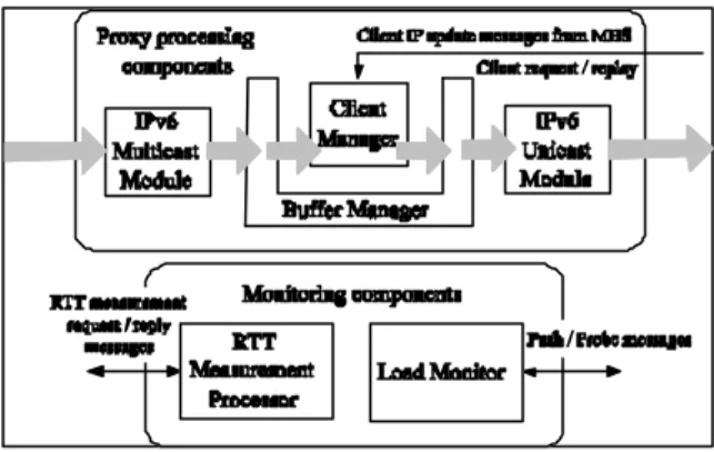
(3) Administrative Manager is in charge of management of the MH's service session. To begin a service session, Administrative Manager accepts the initiation or registration message from the MH. After authentication and authorization, it sends a media menu that records the media ID, which represents the identifier of each media content unit, back to the MH. While the mobile user chooses a specified media ID, the corresponding media contents will be delivered from media servers. l. Location Manager. To keep track of each MH's mobility situation, Location Manager maintains an MH's mobility information table that includes the unique mobile host ID, currently IP address, currently used MRP, past used MRP, APM ID/IP, and media ID. Administrative Manager transmits the mobile user information, which is extracted from registration message, to Location Manager to initiate the MH's mobility information table. When the table has some updates, MHS will report update location information to the corresponding MRP so that media streams can be forwarded to the current location in which the MH locates.. each MRP's performance metric in order to maintain the metric table up to date or (ii) gather each MRP's performance metric that is pushed by the corresponding MRP.. 2.2. The Proxy Level The proxy level consists of a number of Mobile Regional Proxy (MRP) servers and Access Point Manager (APM) servers. MRP mainly provides the function of forwarding media packets from MSs to MHs. APM is in charge of observing each MH's mobility situation and measuring Round-Trip Time (RTT) from the APM to the surrounding MRPs. l. Mobile Regional Proxy (MRP). Figure 3 is the functional block diagram of MRP's internal architecture. Two sets of components that exist in the MRP server are proxy processing components and monitor processing components. Proxy processing components manage incoming packets from MSs and transmit them to the corresponding MHs. Proxy processing components consist of IPv6 Multicast/Unicast Module, Buffer Manager, and Client Manager.. Handoff management components mainly help the MH to discover a suitable MRP using the location-oriented application layer anycasting method and then informs the MH to access media packets through the selected MRP. Handoff management components contain Handoff Controller and Candidate Proxy Manager. l. Handoff Controller. Handoff Controller controls negotiation of proxy handoff and schedules the system workflow. For example, Handoff Controller can communicate with Anycast Manager to discover a suitable MRP or retrieve the MH location information from Location Manager; then, it informs the selected MRP to receive media packets from the corresponding MS, the past MRP to stop receiving media packets from the MS, and the MH to receive media packets from the selected MRP. l. Candidate Proxy Manager. Candidate Proxy Manager mainly performs the candidate MRP selection function using an application-layer anycasting method. Candidate Proxy Manager consists of Anycast Filter and Metric Gatherer associated with a metric table. The metric table records MRP-related information, e.g., proxy server response time, proxy server load, etc. Anycast Filter is used to select a suitable MRP for each MH according to the values of one or more metrics in the table. For example, a weight sum of metrics can be used to allow a user to control the importance of each metric. Metric Gatherer can (i) periodically probe. -3-. Figure 3: The functional block of the Mobile Regional Proxy (MRP). l. IPv6 Multicast/Unicast Module. In order to receive multicast packets from MSs, an MRP has to able to join the corresponding multicast group and receives packets. IPv6 Multicast Module can be informed to join the specified media multicast group, in which the control message is sent from MHS. IPv6 Unicast Module is in charge of the output interface that sends buffered media packets to the MH. l. Buffer Manager. Buffer Manager is responsible for managing each served MH's buffer queue and controlling the store-and-forward functionality. That is, it allocates and initiates buffers for its served MHs and controls how media packets stored in the buffer are enqueued or dequeued..
(4) l. Client Manager. wireless networks and present media contents to the mobile user. Figure 4 depicts the abstract internal architecture of the MH. Three main components that deal with the handoff management are AP Handoff Manager, IP Handoff Manager, and MRP Handoff Manager.. Client Manager is responsible for maintaining all relay sessions from the MS to MHs. It records current IP address of each MH that is served by the MRP. Client Manager is aware of each MH's current mobile location by receiving MH's IP update message sent from MHS in MMTP. Client Manager sends packets to the current location of each MH through IPv6 Unicast Module. l. Load Monitor. Load Monitor is in charge of observing the MRP's load, i.e., the number of MHs that are currently served by the MRP. Load Monitor actively notifies Candidate MRP Manager of MHS if the number of served MHs is changed, i.e. Load Monitor can push the MRP's load information to Candidate MRP Manager. Additionally, Load Monitor accepts queries sent from the MHS. l. RTT Measurement Processor. Figure 4: The hierarchical functional blocks of the. RTT Measurement Processor is in charge of recording the system time. When RTT Measurement Processor receives the Round-Trip Time (RTT) measurement message, it sends back the requested RTT information. In MMTP, the MHS and each APM periodically multicast RTT measurement messages to an MRP anycast group and then a response message containing the MRP IP/ID and time information is sent from each MRP.. mobile host (MH). l. Access Point Manager (APM). In MMTP, each IP subnet is configured with one APM that manages all APs at that subnet. An APM is in charge of observing the mobility situation of each MH that is located at its administrative area. That is, an APM keeps tracks which AP each MH is currently associated with in its administrative area. In order to trigger MRP handoff, we define an APM administrative area as a proxy domain. That is, an MH moves from an APM administrative area to the new one, the new APM will find that an MH is entering into its administrative area and then the APM will trigger the proxy handoff by sending a notification message to the MHS. Additionaly, each APM measures and calculates Round-Trip Time (RTT) between itself and adjacent MRPs. It periodically multicasts the RTT measurement message to an MRP anycast group. By assigning a suitable TTL for multicast packets, the APM can control the measurement range and avoid too much loading in the system.. 2.3. The Client Level An MH can receive media packets from. -4-. l. AP Handoff Manager. In the wireless mobile network, an MH accesses the Internet via APs over wireless links. When an MH is moving, it may leave the wireless coverage of one AP and enters into the other one, which results an AP handoff between APs. In MMTP, the AP handoff is mobile -controlled handoff. AP Handoff Manager is responsible for constantly monitoring the signal quality of its current wireless link. Upon detecting the signal quality is falling below certain threshold, AP Handoff Manager switches to a surrounding AP based on surrounding APs' signal qualities. l. IP Handoff Manager. When an MH moves from an AP's coverage within a subnet to an adjacent AP's coverage, in which the AP is within the other subnet, IP handoff occurs. IP handoff should discover a new access router for the MH's IP handoff and obtain a valid IP address for the routing purpose. Two modes that are generally adopted are stateless mode and stateful mode. In the stateless mode, an MH can receive a router advertisement message or send a router solicitation message to discover the new access router and obtain the router prefix. In the stateful mode, an MH can exchange DHCP configuration messages with the DHCP server in order to obtain the new routing IP address. In MMTP, the stateless IPv6 Neighbor Discovery protocol combined with the AutoConfiguration protocol is adopted to find the access router and get a new IP address. IP Handoff Manager is responsible for (i) observing whether the.
(5) MH's routing IP address needs to be changed, (ii) retrieving the routing IP address from the IPv6 protocol stack kernel and, (iii) sending the IP address update information message to the MHS that provides mobile multimedia services. l. MRP Handoff Manager. When the MH is moving from one AP's coverage within a proxy domain to an adjacent AP's coverage in which the AP is within the other proxy domain, the MRP handoff occurs. That is, the MH needs to switch the served MRP to the one which is selected by the MHS. MRP Handoff Manager is responsible for triggering MRP handoff and MRP setup and configuration. When MRP Handoff Manager is notified by the MHS to have MRP handoff, it extracts the MRP information from the control message and sets MRP configuration to the specified MRP. Then, multimedia client applications will start to receive media contents from the new MRP.. 3. The handoff operations In MMTP, handoff management is the key concern that needs to be resolved. In this Section, we describe the operations of (1) AP handoff, (2) IP handoff, and (3) Proxy handoff in detail.. 3.1 AP Handoff and IP Handoff When an MH moves from the radio coverage of one AP to the other one, the MH needs to change the associated AP. In this way, the MH can continuously access the Internet through the wireless interface. AP handoff belongs to the layer 2 (L2) handoff. AP handoff is transparent to the routing at the IP layer and the media session at the application layer. The L2 handoff can be network-initiated or mobile -initiated. If the MH wants to control the AP handoff according the specific decision algorithm, the L2 protocol stack needs to provide proper APIs.. That is, when an MH switches to one neighboring AP that is not managed by the original APM, the new APM will generate the proxy handoff notification message and send it to MHS. To enable seamless proxy handoff, an MH needs to discover candidate MRPs for proxy handoff. The discovery process is performed using the application layer anycasting method in MMTP. The application layer anycasting service is accomplished through Candidate Proxy Manager of the MHS, which consists of Anycast Filter and Metric Gatherer associated with a metric table. MRP-related parameters are elements of the metric table. Metric Gatherer is a daemon that deals with the collection of metric values. Anycast Filter is in charge of selecting which MRP is optimal to the MH based on the metrics of the table.. 4. Performance Evaluation Figure 5 depicts the configuration of the experiment environment. A mobile server cluster MSC that contains a mobile handoff server MHS and a media server MS is associated with IP domain subnet C. Three mobile regional proxy servers MRP 1, MRP 2, and MRP3 are set in IP domains subnet A, subnet B, and subnet C, respectively. Two access point managers APM A and APM B located at subnet A and subnet B to form proxy domain A and proxy domain B, respectively. All servers are connected through wirelines that are with duplex 10Mbps bandwidth. APM A and APM B are monitoring Compaq WL410 802.11b access points AP 1 and AP 2, respectively. The coverage of AP 1 and AP 2 are contiguous along a straight line but disjoint. A mobile host MH using Orinoco 11Mbps wireless PCMCIA card communicates with the IPv6 network via APs.. For AP handoff, if the new AP is associated with a new subnet, the MH's IP address should be changed and thus the corresponding MRP should be informed of IP update. IP handoff is to change layer 3 (L3) routing reachability point when an MH moves between IP subnets. IP handoff should be transparent to the media session at the application layer. The L3 protocol stack of the MH needs to have a mechanism to obtain the new IP address and to send the message to the corresponding hosts. Figure 5: The experiment environment configuration.. 3.2 Proxy Handoff When the MH is moving from one AP's coverage within a proxy domain to an adjacent AP's coverage in which the AP is within the other proxy domain, proxy handoff occurs. In MMTP, we define a proxy domain as the administrative area of an APM.. -5-. 4.1. Examination of handoff latency In the latency test, AP handoff latency, IP handoff latency, and proxy handoff latency in MMTP are measured. AP handoff latency is defined as the.
(6) time period from the time at which the MH sends handoff request to the new AP to the time at which the first packet is received from the new AP. IP handoff latency is defined the time period from the time at which the air link with the new AP is reconnected to the time at which the MHS finishes updating the IP address of the MH to the MH mobility information table. The proxy handoff latency is defined as the time period from the time at which the MHS receives the ProxyHandoff request to the time at which the MH receives the first packet sent from the new MRP. In this experiment, we also use the experimental testbed depicted in Figure 5. The scenario is that MS sends MPEG-1 streaming packets with the spead of 1.5 MB per second to the MH that is in subnet A through MRP 1. The MH is moving between AP 1's radio coverage and AP 2's radio coverage. That is, the MH is moving between subnet A and subnet B or between proxy domain A and proxy domain B. Therefore, when the signal quality between the MH and the associated AP falls below certain minimum threshold, the MH starts to do AP handoff, IP handoff, and proxy handoff in succession. We observe and find out the time needed for completing related handoff procedures. The average latency for each AP handoff latency, IP handoff latency, and proxy handoff latency were computed and compared. The experiment was repeated 20 to 30 times and measured times were averaged.. 4.2. Configuration of Handoff Threshold In order to determine when the MH should do AP handoff when the signal quality of the currently used wireless link is becoming worse, we need to know the relationship between throughput and signal quality and between packet loss rate and signal quality such that we can define the AP handoff threshold. The test items for handoff threshold contains throughput, packet loss rate, and signal quality. Figure 7 depicts this experimental environment confguration. It consists of a wired server, an IPv6 router, an access point, and a wireless client. The wireline connection part is 10 Mbps Ethernet and the wireless connection part is 802.11b. The wireless client uses Orinoco 11Mbps wireless PCMCIA card to access the Internet. The access point (AP) is Compaq WL410 802.11b access point.. Figure 7: The experiment configuration of testbed l. Throughput. Throuhput is a measurement of how fast data moves from a wired server to a wireless client via an access point. The test sends a file at the 500kbps rate from the wired server to the wireless client, measures how much time it takes, and calculates the result. When the wire less client moves far away AP slowly, which results in worse signal quality, throughput will decrease to reflect signal quality. l. Figure 6: The experiment result of AP, IP, proxy handoff latency. Figure 6 depicts the experiment results. The processing time of AP handoff is in the range between 272 ms and 204 ms. The average time is about 228.5 ms. The processing time of IP handoff is in the range between 1.08 s and 0.753 s. The average time is about 0.868 s. The processing time of proxy handoff is in the range 2.02 s and 2.90 s. The average time is about 2.381 s. Therefore, the average system handoff latency for achieving AP, IP, and proxy handoffs is about 4.477 s.. -6-. Packet Loss Rate. The test measures how well a continuous stream of data is handled. The test is based on UDP. The wired server continuously pushes data at the 500Kbps rate to the wireless client when the wireless client is moving far away AP. When signal strength between AP and wireless client is becoming worse and worse, the packet loss situation may occurs. In other words, packet loss rate will increase to reflect signal quality. l. Signal Quality. When throughput and packet loss rate are measured, we can retrieve RSSI (Received Signal Strength Identifier) values from miniport driver of the wireless card using L2 APIs. In our test, RSSI values can be used as signal quality parameters of the.
(7) antenna/radio system. In general, a change of MH's location always directly affects the signal quality. Thus, observing RSSI values gives information about the MNs movements. RSSI is measured in dBm and higher numbers mean that signal quality is better.. transmission platform, called MMTP, and a control scheme to support proxy handoff (layer 7 handoff) in this paper. Three handoff types that are distinguished in MMTP are AP handoff, IP handoff, and layer 7 handoff, i.e., proxy handoff. Two goals that the proposed layer 7 proxy handoff scheme wants to archieve are location-oriented selection and load balance. Our proxy handoff scheme adopts the application layer anycasting method to achieve the two goals. Using the anycasting technique, a suitable proxy is selected to serve the MH according to MH's current location and the load of candidate proxies.. Reference [1]. M.. Endler. and. V.. Nagamuta,. Approaches. for. Implementing. General Seamless. Handover, Proceedings of the 2th ACM International. Workshop. on. Principles. of. Figure 8: hroughput vs. Signal Quality Mobile Computing, pp. 17 - 24, Oct. 2002. [2]. S. Hadjiefthymiades and L. Merakos, ìUsing Proxy Cache Relocation to AccelerateWeb Browsing. in. Wireless/. Mobile. Communications, Proceedings of the 10th International Conference on World Wide Web, pp. 26 - 35, May 2001. [3]. R. Koodli, Fast Handovers for Mobile IPv6, Internet draft, Mar. 2002.. [4]. S. Pack and Y. Choi, Pre -Authenticated Fast Handoff in a Public Wireless LAN based on. Figure 9: Packet loss Rate vs. Signal Quality IEEE 802.1x Model, IFIP TC6 Personal Figure 8 depicts the relationship between bandwidth and RSSI and Figure 9 depicts the relationship between packet loss rate and RSSI. When RSSI values are in the range of -40 to -80, actual throughput is close to 500Kbps and the packet loss rate is almost ideally zero. That is, throughput and packet loss rate do not have too much affects when signal strength is good. When RSSI values are smaller than -80, packet loss rate increases very quickly and throughput also slows down very quickly. Therefore, we can define the AP handoff minimum threshold to be in the rang of -70 and -80. That is, when the MH detects the signal quality between itself and the assoicated AP is in the range between -70 and -80, the MH scans the surrounding APs and does handoff to the new AP, which is assiciated with the better signal quality.. Wireless Communications, Oct. 2002. [5]. C. E. Perkins, Mobile IP and the IETF, ACM SIGMOBILE. Mobile. We have proposed a 3-tier multimedia mobile. -7-. and. Communications Review, VOL. 4, NO. 3, pp. 6 - 11, 2000. [6]. J. Seitz, K. Cheverst, N. Davies, M. Ebner, and A. Friday, Management of Proxy Objects Providing Multimedia Applications in the Mobile Environment, Proceedings of the 6th IFIP/IEEE. International. Symposium. on. Integrated Network Management, pp. 915 928, May 1999.. 5. Conclusion. Computing.
(8)
數據


+3


相關文件
¾ Relocation, which modifies the object program so that it can be loaded at an address different from the location originally specified.. ¾ Linking, which combines two or
Teacher starts the lesson with above question and explains to students that making business decision is one of the basic functions of a
Since the sink is aware of the location of the interested area, simple greedy geographic routing scheme is used to send a data request (in the form of
Take a time step on current grid to update cell averages of volume fractions at next time step (b) Interface reconstruction. Find new interface location based on volume
Take a time step on current grid to update cell averages of volume fractions at next time step (b) Interface reconstruction.. Find new interface location based on volume
(a) The principal of a school shall nominate such number of teachers of the school for registration as teacher manager or alternate teacher manager of the school as may be provided
Then they work in groups of four to design a questionnaire on diets and eating habits based on the information they have collected from the internet and in Part A, and with
The aim of this theme is to study the factors affecting industrial location using iron and steel industry and information technology industry as examples. Iron and steel industry
