All-Optical IP-over-DWDM MAN Ring Network with CSMA/CP MAC Protocol
7
0
0
全文
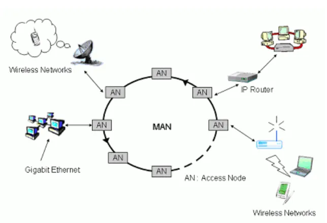
(2) jamming signally mechanism to handle the optical. packet. collision.. The. W data channels as show in Fig 1.. data/packets. regeneration may minimize the number of erbium-doped fiber amplifiers (EDFA’s) and reduce amplifier noise accumulation, however the O/E conversion may also constrain the transmission rate of the high speed DWDM backbone network. This paper proposes a novel network with CSMA/CP (Carrier Sense Multiple Access with Carrier Preemption) protocol to transmit IP. Fig 1. Network architecture for MAN ring networks.. packets directly over the DWDM network instead of encapsulating them into SONET. Each access node is composed of two. frames. It is a all-optical network that eliminates. interfaces: the Gigabit Ethernet interface is used. all O/E conversion. For achieving all-optical,. for transmission between the access nodes and. the DWDM network is implemented by the. the access networks, the Optical-Link interface. Sub-Carrier Multiplexing (SCM) technique to. is used to access the DWDM MAN ring in. mix the sub-carrier frequency multiplexed tones. optical domain. Each node is also equipped with. as packet headers and employ RF detection. a tunable transmitter and multiple fixed. techniques to monitor the availability of. receivers; each receiver takes case of a. wavelengths [1][4][10].. particular data channel which owns a unique. Following the introduction, this paper is. specific wavelength. Nodes can simultaneously. organized as following. Section II introduces the. receive data from any wavelengths (or receivers).. network architecture and the proposed MAC. Channels can works independently without. protocol. Section III presents the simulation. mutual interference to each other. Logically, the. model and simulation results to demonstrate the. network can be treated as a multi-ring network.. system performance such as transmission delay and queuing delay. It also studies the effect of various system parameters and compares the proposed architecture to the presented single fixed receiver architecture in open literature.. II. System Architecture A. The Network Architecture The proposed network architecture is based. Fig 2. Structure of Access Nodes. on a single unidirectional fiber ring topology, it The node structure is shown in Fig 2. The. consists of a number of access nodes (ANs) and. 2.
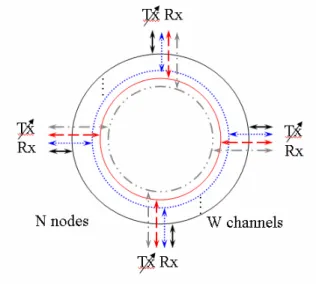
(3) optical signal sent from upstream nodes will be. fiber first, and then sent to downstream nodes.. tapped off a small portion of optical power from. B. CSMA/CP Protocol. the ring to receivers by the splitter. Every. In the network architecture, each node has the. receiver continuously monitors the sub-carrier. ability to access any wavelength and statistically. frequencies carried in all opened wavelength to. shares the bandwidth of each data channel. A. detect whether the wavelengths are transmittable. logical architecture is shown in the figure 3 for. or not, and to inspect the header information.. the case of four wavelengths and four nodes.. According to the information, the data packets will be passed to the local network if their destination addresses does match the node address. Meanwhile, the MAC control scheme is signaled to activate the Fiber Bragg Grating (FBG) Filter for filtering the received packet that carried in major portion of the optical signal through the delay line. If the destination address does not match to the node address, the retrieved packet is ignored, the node then continuously scans the next packets. When the optical signal goes through the Fig 3. Logical Architecture. delay line, it will be delayed a period of delay time for the operation of address recognition and the adjusting of phase mask for the FBG Filter. To avoid packet collision and efficiently. in order to drop the specified wavelength. In this. govern the unprecedented bandwidth, this paper. network architecture, the destination removal. proposed a novel carrier preemption Medium. policy is used.. Access Control (MAC) protocol that is based on. The transmitting packets are added into the. carrier sense multiple access scheme. The. transmission queue before sending. Each node is. carrier sensing mechanism is used by receiver to. equipped with multiple fixed receivers where. inspect the sub-carrier signaling of transmitted. each takes case of a data channel, hence the. packets in optical fiber. Each wavelength is. receivers may detect more than one available. associated with a sub-carrier frequency. Nodes. data channels at the same time. However, there. detect the availability of wavelengths by. is only a tunable transmitter to transmit packet. monitoring the sub-carrier in RF domain.. on a specified wavelength at a time; this paper. To solve the access collisions in the network,. uses the random selection strategy to make the. each node monitors the wavelengths and tries to. decision for it. As packets will be transmitted. find an opening window on channels for packets. onto the available data channel, the optical. transmission. Transmitting packet onto a target. carrier of packets and the sub-carrier frequency. channel while the other packet (called carrier). multiplexed tones are coupled into the optical. from upstream node is arrived at the node on the. 3.
(4) same channel, and a collision is occurred. The. which labels the data frame which is conveyed. reason for collision happens is that nodes do not. in data channel either for packets or fragments.. have enough information to know whether the. The destinations address (DA) and the source. opening. address (SA) field record address information in. window. is. long. enough. to. accommodate the packet.. the network. The sequence number (SN). In the carrier preemption scheme, a collided. expresses the serial number in a sequence of. packet which transmission does not finish will. fragments and end fragment (EF) field is used to. be immediately fragmented into two parts: one. indicate the last fragment. Finally, the flag field. should be transmitted and the other must still be. (FG) is reserved for extended protocol functions. in queue is shown in Fig 4. The transmitter can. such as define different service class for the data. continually transmit the former when the arrival. payload. Fig. 6 shows how the packet is. carrier passes into the delay-line. Until the. fragmented into two parts if packet collision. carrier through delay-line after Ti nano-seconds,. happened. Each packet must append frame. the. header either being transmitted or being. transmitter. just. finishes. the. former. transmission. For the fragment in queue, it will. fragmented.. be transmitted later on the same channel or on other available channels.. Fig 5.The frame format Fig 4. (a) Carrier Sense (channel i). Fig 6. The data frame fragmentation. III. Simulation and Results Fig 4. (b) Carrier Preemption (channel i). This study adopts the SIMSCRIPT language to implement the simulation programs. Fig. 7. To support the carrier preemption scheme, the. shows the simulation model of the access node.. frame format is designed as shown in Fig. 5. It. In the model, the upstream traffic is generated. is adopted as the solution of the addressing. by the upstream nodes instead of using the. capabilities and fragmentation mechanisms [5].. traffic. Basically, it consists of a start delimiter (SD),. destination address of the packet on each. 4. generator.. Each. node. checks. the.
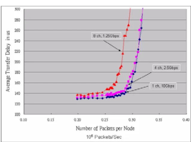
(5) wavelength from the upstream nodes. If. Figure 8 shows the relation of the average. destination address matches the node address,. transfer delay versus the number of packets per. the packet is received, and calculated its. node in a 10Gbps DWDM ring with various. transmission latency. Otherwise, the packet will. numbers of channels. Under the steady state. be added into the delay-line queue by the CHK. network condition, the higher the number of. module.. channels in the DWDM ring obtains the higher the node throughput. The means the throughput characteristic of the network depends on the aggregated transmission capacity of the network. We also compare the single receiver case of this network, as the number of channels increased the difference of performance is increased.. Fig 7. Simulation Model of the access node The CHK module is also responsible to fragment the transmitting packet to avoid collision by using the carrier preemption scheme. The simulations are processed under various parameters for the symmetric traffic. The symmetric traffic means that the arrival traffic of every node is equal, and their destinations are. Fig 8. Average transfer delay for various the number. even to other nodes. The transmission-delay is. of channels. measured from the time the packet is completely stored in the transmit buffer of a source node to the time the packet is completely received by the receive buffer of a destination node. To evaluate the performance of the DWDM ring network, the assumption for the simulation parameters have shown in Table 1. Table 1 Network Parameters Number of nodes. 16. Number of channels. 1, 2, 4, 8. Ring distance. 50km. Channel speed. OC-192 (10Gbps). Size of the delay line. 80ns. transfer delay will be small changed between the. Average IP packet size. 512 bytes. networks with various channels as shown in Fig. Fig 9. Average transfer delay for various channel speeds and the number of channels. In constant total bandwidth case, the average. 5.
(6) 9: eight-channel of 1.25 Gbps DWDM ring,. Network Based on CSMA/CA Packet. four-channel of 2.5 Gbps DWDM ring and. Switching”, IEEE Photon. Technol. Letters,. single-channel of 10Gbps DWDM ring. The. vol. 11, no. 11, November 1999.. reason of the difference in the node latency is. [2] I. M. White, K. Shrikhande, M. S. Rogge, S.. each node only has a tunable transmitter. In. M. Gemelos, D. Wonglumsom, G. Desa, Y.. single channel case, the transmitter only. Fukashiro, L. G. Kazovksy, “Architecture. transmits optical packet in fixed channel without. and Protocols for HORNET: A Novel. any tuning operation. However, in multiple. Packet-over-WDM Multiple-Access MAN”,. channel case the tunable transmitter has to be. GLOBECOM 2000, San Francisco, CA,. tuned to other channel and use the random. November 2000.. selection policy to choose the available channel.. [3] K. Shrikhande, I. M. White, M. S. Rogge, D.. The tuning time and the selection times will. Wonglumsom, S. M. Gemelos, L. G.. increase the additional transfer delay.. Kazovksy, “CSMA/CA MAC Protocols for. IV. Conclusions. IP-HORNET:. An. Metropolitan. Area. IP. over. Ring. WDM. Network”,. GLOBECOM 2000, San Francisco, CA, This paper proposes a novel MAC protocol. November 2000.. for all optical DWDM ring networks. The. [4] C. L. Lu, D. J. M. Sabido IX, P. Poggiolini,. protocol supports the transmission of IP packets. R. T. Hofmeister, and L. G. Kazovsky,. directly over DWDM networks. Meanwhile, this. “CORD-A. novel network architecture accommodates an. Subcarrier-based signaling and control. arbitrarily number of nodes and each node can. scheme,” IEEE Photon. Technol. Lett., vol.. operate independently. Simulation results show. 7, May 1995.. WDMA. optical. network:. the excellent characteristics of high throughput. [5] Wen-Shyang Hwang, Wen-Fong Wang,. and low latency in the way of all optical. Jun-Yao Wang, Chien-Chun Li, “A Carrier. communication.. Preemption Access Control Protocol for Supporting IP Packets over WDM Ring. Acknowledgment. Networks”, ISCOM 2001 [6] Christophe S. Jelger and Jaafar M. H.. This work was supported by the National. Elmirghani, “A Simple MAC Protocol for. Science Council (NSC), Taiwan R.O.C. The. WDM. Project number is NSC 90-2213-E-151-014-.. Networks”, GLOBECOM 2001, vol. 3,. Metropolitan. Access. Ring. 2001. References. [7] Hyuek Jas Lee, S. J. B Yoo, Vincent K. Tsui, and S. K. H. Fong, “A Simple All-Optical. [1]S.. M.. Gemelos,. I.. M.. White,. D.. Label Detection and Swapping Technique. Wonglumsom, K. Shrikhande, T. Ono, and. Incorporating a Fiber Bragg Grating Filter”,. L. G. Kazovsky, “ WDM Metropolitan Area. IEEE Photon. Technol. Letters, vol. 13, no.. 6.
(7) 6, June 2001. [8] Lisong Xu, Harry G. Perros, and George Rouskas, “Techniques for Optical Packet Switching and Optical Burst Switching”, IEEE Communications Magazine, January 2001. [9] Christophe S. Jelger, and Jaafar M. H. Elmirghani, “Performance of a slotted MAC Protocol for WDM Metropolitan Access Ring Network under Self-Similar traffic”, IEEE International Conference on , Volume: 5 , 2002.. [10] Rongqing Hui; Benyuan Zhu; Renxiang Huang; Allen, C.T.; Demarest, K.R.; Richards, D. “Subcarrier multiplexing for high-speed optical transmission “, IEEE Lightwave Technology, Journal , vol 20 Issue: 3 , March 2002, pp.417 -42.. 7.
(8)
數據
相關文件
(A) NAT (Network Address Translation) (B) DHCP (Dynamic Host Configuration Protocol) (C) DNS (Domain Name Server) (D) ARP (Address Resolution
A host connecting to the outside network is allocated an external IP address from the address pool managed by NAT... Flavors of
Signaling over standard IP uses a common transport protocol that ensures reliable signaling delivery. Error-free
Responsible for providing reliable data transmission Data Link Layer from one node to another. Concerned with routing data from one network node Network Layer
In the work of Qian and Sejnowski a window of 13 secondary structure predictions is used as input to a fully connected structure-structure network with 40 hidden units.. Thus,
Transfer the P-CSCF address with the PDP Context Activation signaling to the UE. GGSN acts as a DHCP Relay Agent 1.Create PDP context bearer ( TS 23.060) 2.UE requests a
3. Works better for some tasks to use grammatical tree structure Language recursion is still up to debate.. Recursive Neural Network Architecture. A network is to predict the
To tackle these problems, this study develops a novel approach integrated with some graph-based heuristic working rules, robust back-propagation neural network (BPNN) engines
