Anti-competition of laser modes in semiconductor lasers
Chi-Chia Huang a
Ching-FuhLin a,bYu-Chen Yu C
and Yi-Xiong
Lin Ca Graduate
Inst. of Electron-Optical Engr., National Taiwan Univ., Taiwan
b
Dept. ofElectrical Engr.and Graduate Inst. ofElectronics Engr., National Taiwan Univ., Taiwan
C
Industrial
Technology of Research Institute, Chutung, Hsinchu, Taiwan
ABSTRACT
Anti-competition of laser modes is observed in dual-wavelength semiconductor lasers with single gain medium. Under anti-competition, the increase of intensity of one lasing mode could enhance the intensity of another mode, which is opposite to the usual mode competition. In our experiment, anti-competition can be observed for wavelength separation larger than 1 1 1 nm, and gradually disappears for wavelength separation less than 100 nm. Besides, anti-competition can also be influenced by the intensity and the wavelength position of both modes. A simple theoretical analysis shows that anti-competition is due to the physics similar to optical pumping.
Keywords: mode competition, anti-competition, two-mode semiconductor laser, nonidentical multiple quantum wells, broadband semiconductor optical amplifier.
1. INTRODUCTION
Mode competition is a well-known phenomenon in lasers. Soon after the invention of lasers, competition of laser modes has been observed and analyzed [1]. In a multi-mode laser system, different modes will in general have different gains, losses and saturation parameters, and will compete for the available population inversion in the laser. Since the total gain of a laser system is constant under fixed external pumping level, oscillation in one mode will generally reduce the gain available for another mode, and in some situations may suppress the other mode entirely [2]. Under strong coupling condition, competition can lead to bistability ofthe two lasing modes [3], which has been analyzed through perturbation stability analysis [2]. Competition can also lead to tristability [4, 5] and even chaotic behaviors [6, 7]. Those phenomena are found useful for optical switching, optical logic, data encryption [8, 9], and so on. Competition dynamics is also an important phenomenon in injection locking [10], mode locking [1 1-13], and cross gain modulation in optical amplifiers [14]. For many years, the appearance of competition has been taken for granted among laser modes, and is thought to be inevitable. However, we have discovered a behavior opposite to competition between lasing modes. That is, the increase ofthe oscillation intensity in one lasing mode was found to enhance the intensity ofanother mode. This behavior is what we called anti-competition of laser modes.
In this work, we will demonstrate that anti-competition can be observed at wavelength separation larger than 111 nm. Besides, the larger the wavelength separation is, the more apparent anti-competition can be observed. Some other influential factors of anti-competition will also be demonstrated, including the intensity and the wavelength position of the two oscillating modes. A simple theoretical analysis will be given, which shows that anti-competition is due to the physics similar to optical pumping.
2. EXPERIMENT
2.1 Broadband gain medium design
Since anti-competition can be observed only when the WS is larger than 1 1 1 nm, a broadband laser gain medium is
necessary. Quantum-well (QW) engineering is a convenient, widely used approach to broaden the bandwidth of
semiconductor superluminescent diodes (SLDs). This scheme includes using a single QW with simultaneous transitions of n = 1and n =2states [15,16], and using nonidentical QWs [17-20]. Because the simultaneous transitions of n =1 and
n =
2energy states in identical QWs rely strongly on the device lengths [15,16], nonidentical multiple quantum wells (MQWs) were recently been widely used for broadband purposes.l5nm
In086Ga 14As03P07
1II[1J1J1J
6nm IIn067Ga33As072P028 8.7nm
In0 53Ga0 47As
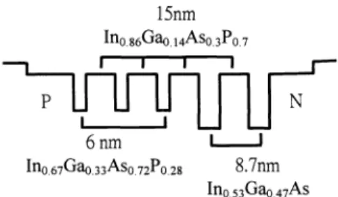
Fig. 1. Designed QW structure.
However, theoretically analysis has predicted that carrier distribution among the MQWs is nonuniform [17, 18]. Experimental evidence ofthis phenomenon was also indirectly obtained from the characteristics of laser diodes [19, 20]. Nonuniform carrier distribution means that each QW of the MQW structure accumulates a different number of carriers, so their corresponding emission intensities are not equal. Thus, the overlap ofthe individual spectrum from each type of QW, weighed by its corresponding emission intensity, does not directly result in a broadband spectrum. Investigation on
the influential factors of the nonuniform carrier distribution in order to achieve broadband characteristics is thus important [19-21]. With proper design of the nonidentical QW structure, extremely broad bandwidth of the gain
medium ofthe semiconductor lasers/amplifires is possible [22].
The designed QW structure is shown in Fig.1 .
A
separate confinement heterostructure (SCH) is formed in connection with the wells. The SCH layer has a thickness of 120 nm. The wells are separated by 15-nm-wideIn86Ga14As03P07 barriers. Three 6.0-nm In067Ga33As072P028 QWs are placed near the n-cladding layer, and two 8.7-nm In053Ga47As QWs are placed near the p-cladding layer. The emission energies of the 6.0-8.7-nm In067Ga33As072P028 QW and 8.7-nm In053Ga47As QW were calculated using the Luttinger-Kohn method [23]. Table I shows the emission wavelengths corresponding to the calculated energy levels. In067Ga33As072P028 QWs and In053Ga47As QWs have three and two quantized energy levels, respectively.
For this QW structure, emission at low injection current occurs at the wavelength corresponding to the n 1
transition in the 8.7-nm In053Ga47As QWs, which are close to the n-cladding layer. When the injection current increases, the emission spectrum is broadened owing to the simultaneous transitions of n 1 and n 2 states. The
emission contribution from the 6.0-nm In067Ga33As072P028 QWs is obvious only when the injection current is very large. In our experiment, we use laser diodes (LDs) with straight waveguide. This is because, compared with the tilt or bent waveguide superluminescent diodes (SLDs), the straight-waveguide LD has lower loss and lower threshold current. This can facilitate the tuning of the modes above 1 500 nm because those modes are very loss-sensitive. The length of the device was about 300 .tm. No facet coatings were applied to the device. The measured emission spectrum ofthe LD is shown in Fig. 2. The bandwidth of the emission spectrum is limited by the Fabry-Perot resonance of the straight waveguide LD. The operation temperature and current are 22.7 °C and 146 mA, respectively. The operation current is only 3 mA larger than the threshold current of the Fabry-Perot mode, so the oscillation of the Fabry-Perot mode is still negligible.
TABLE I. Calculated Transition Wavelengths Corresponding to the Bounded Energy States of the Nonidentita1 MQWs of the Designed SLD
n 8.7-nm In0 53Ga0 47AsDouble QW (jim)
6.0-nm In067Ga033As072P028 Triple QW (jim) 1 2 3 1.54 1.46 1.18 1.3 1.24 Unbounded
2.2 Experimentalsetup and steps
Our experimental setup is shown in Fig. 3. Theexternal cavity is of reflected-type grating telescope configuration. Two
collimators with f 4.5
mmand NA 0.55
areused to collimate the light beams emitted from two facets of the LD. The coupling efficiency of the collimators is about 70%. The grating is 600 lines/mm and is Au-coated. Its efficiency isabout 80%. A lens with f =10 cm is placed at 10 cm from both the grating and the mirror M2. The insertion of the mirror Ml and two physically separated mirrors for the mirror M2 are for the purpose of broadband tuning range. A double-slit is used for selecting the short-wavelength mode (SWM) and the long-wavelength mode (LWM), and a ND filter is put in front of each slit to control the light power of each mode at the same time.
a
04291 300tm straight
Fig. 2. Measured emission spectrum of the SLD.
Lock-in amp.
Fig. 3. Experimental setup.
By varying the loss of the ND filter in front of the slit, we can change the intensity of the controlled mode. When
the intensity of either mode is changed, the intensity of the other mode also varies due to the competition or
anti-competition. Plotting out the variation of the power of those modes, we can obtain several curves on the power plane,
where the two axes represent the power of the SWM and the LWM, respectively. Moreover, if the vertical axis
represents the power of the LWM, then the external loss introduced to the LWM must be kept constant throughout the measurement, and vice versa. The experiment for obtaining the curve with the vertical axis representing the power of the LWM goes through as follows. First, we choose the double-silt of certain mode spacing. The grating at the output
diffracts the two oscillation wavelengths chosen by the double-slit, and their light power is measured through two
detectors and an oscilloscope. Next, we tune the left ND filter (the one corresponding to the SWM) to a certain value of loss, and again measure the light power of both modes. Because the holding stage of the optical components in the
external cavity is not very stable, the ND filter of the LWM is tuned for keeping the external loss a constant if
necessary. This step is repeated until we have tuned the ND filter to its maximum loss, and the light power of the SW mode is about to vanish. After that, we have obtained a curve with certain external loss, or say, certain initial power of the LWM. Then, we tune the ND filter ofthe LWM to change the external loss, and follow the steps mentioned above to obtain another curve with this new external loss and initial power of the LWM. Finally, we remove the grating and the detectors and use the monochromator to measure the spectrum. For obtaining the curves with vertical axis represents the power ofthe SWM, the experimental steps are similar to that described above.
2.3 Experimental results and discussion
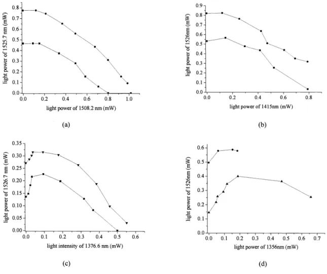
Our experimental result for wavelength separation 1 8 nm is shown in Fig. 4 (a). We see that, under this wavelength separation, the curves are of negative gradient. That is, the light power of the LWM decreases with the increasing of the
light power of the SWM. This is the same as the well-known mode competition. Howevre, when the wavelength
separation is increased to 1 1 1 nm (see Fig. 4 (b)), a curve with positive gradient appears on the plane. That is, increasing the light power of the SWM leads to the increase of the light power of the LWM. This behavior is opposite to mode competition, so we call it mode anti-competition. Some experimental results for larger wavelength separation are shown
0.6
U-L
I
0.0 0.2 0.4 0.6 0.8 light power of 1508.2 nm(mW) (a) 0.8 0.7 0.5 0.4 0.3 0.2 0.1 0.9 0.8 0.7I
0.2
0.1 1.0 E E 0 0) 0 .0 0.0 0.2 0.4 0.6 0.8 light power of 1415mn (mW) (b)/
/
0.6 0.5:.:
0.2
0.1
0.0 0.1 0.2 0.3 0.4 0.5 0.6 light intensity of 1376.6 nm (mW) 0.0 0.1 0.2 0:3 0:4 0.5 0.6 light power of 1356nm (mW) (d) 0:7 (c)Fig. 4. Variation ofthe light power ofthe LWM to that ofthe SWM at wavelength separation of: (a) 18 nm, (b) 111 nm, (c) I 50nm,(d) I 68 nm.
in Fig. 4 (c), (d).
Next, some influential factors of anti-competition are investigated. The first one is wavelength separation of the two modes. From Fig. 4, we can see that at larger wavelength separation, the slope of the positive-gradient curve is
steeper, and the maximum power the LWM can reach under fixed initial power is larger. That is, the larger the
wavelength separation is, the severer anti-competition is. For example, when the initial power of the LWM(thepower ofthe LWMwhenthe power ofthe SWM is zero) is fixed to about 0. 14 mW, anti-competition can cause the light power
ofthe LWMtoincrease to about 0.23 mW and 0.4 mW at wavelength separation 150 nm and 168 nm, respectively (see Fig. 4 (c), (d)). In addition, for those two curves, the slopes of the positive gradient region are about 1 .5and 1 .8 at
wavelength separation of 150 nm and 168 nm, respectively.
The second influential factor is the light power of the SWM. From Fig. 4, we see that no matter which wavelength separation is, anti-competition can exist only when the light power of the SWM is below certain level. For example, at wavelength separation of 150 nm and 168 nm (see Fig. 4 (c), (d)), anti-competition can exist only when the light power
of the SWM is below 0. 1 mW and 0.2 mW, respectively. Above this level, anti-competition disappears, and the
interaction between these two modes gradually turns into competition. In general, this power level, or say, the existing range of a anti-competition, is larger at large wavelength separation. During the transition from anti-competition to competition, region exists where the variation of the SWMpowerhas no influence on the LWMpower.The existing
range of anti-competition seems larger at wavelength separation 1 1 1 nm than at 1 50nm.This is because, at wavelength separation 1 1 1 nm, we only sample two points when the power of the short-wavelength mode increases from 0 mW to 0.18 mW (see Fig. 4 (b)). Therefore, in Fig. 4 (b), the maximum power of the long-wavelength mode (or say, the end point of anti-competition) should have appeared prior to our second sample point, but that point was missed.
The third influential factor is the initial power of the LWM. In general, anti-competition is severer when the initial power ofthe LWMissmaller. This can be verified from Fig. 4 (b), (c), (d).
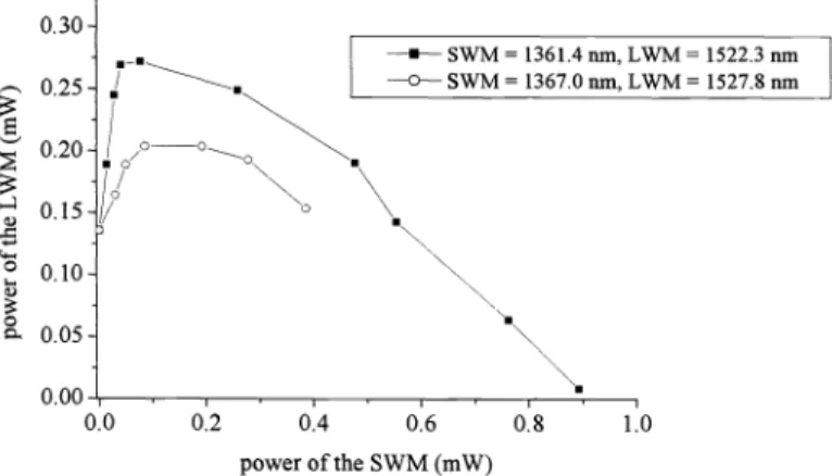
The last influential factor of anti-competition is the wavelength position of the two modes. As shown in Fig. 5,
anti-competitionat fixed wavelength separation 1 60 nm can have different behaviors because of different wavelength
positions. When both modes reside in the longer wavelength region, anti-competition is severer. The same phenomenon can be observed for wavelength separation larger than 140 nm. When the wavelength separation is smaller than 140 nm, a phenomenon behaves in the opposite way appears. That is, when both modes reside in the longer wavelength region, anti-competition is less obvious.
2.4 Reasons for anti-competition
The reasons for anti-competition are as follows. First, as discussed above, the emission spectrum of the laser gain medium is the overlap of the emission spectra of two different QWs. Since in our experiment, the wavelength position of the LWMisalways above 1510 nm (see Fig. 4, 5), mostof the carriers for the oscillation of the LWM are mostly
0.30 _________________________________________ —--—SWM=1361.4om, LWM= 1522.3nm 0 25
/ —=
—0-— SWM=1367.0nm, LWM= 1527.8nm 0.20 //OO
0.15 Q o N a 0.0 0.2 0.4 0.6 0.8 1.0 power of the SWM (mW)contributed from the n 1 state of the 8.7-nm In053Ga47As QWs. However, the wavelength position of the SWM
ranges from 1356 nm to 1415 nm at wavelength separation ranging from 168 nm to 111 nm. Therefore, both the 6.0-nm In067Ga33As072P028 QWs and the n =2 state of the 8.7-nm In053Ga47As QWs contribute to the carriers for the
oscillation of the SWM. The ratio of the carrier contribution form these two types of QWs to the SWM depends on the wavelength position of the SWM. If the SWM is located near 1300 nm, the In067Ga33As072P028 QWs have more
contribution to the gain, and vice versa. Therefore, at wavelength separation 1 1 1 nm (see Fig. 4 (b)), the two
wavelengths are nearly contributed from the In053Ga47As QWs. On the other hand, at wavelength separation 1 68 nm
(see Fig. 4 (d)), the SWM and LWM are nearly contributed from the In067Ga33As072P028 QWs and the In0 53Ga0 47As
QWs, respectively. Therefore, competition at wavelength separation 1 68 nm is weaker than at 1 1 1 nm (as shown in Fig. 4) because the carrier transportation between different QWs is a relatively slow process, compared with the intraband relaxation in the same well.
The second reason is, because the photon energy of the short-wavelength QWs is larger than that of the
long-wavelength QWs, some of the emitted short-long-wavelength photons will be absorbed by the long-long-wavelength QWs. This can provide the long-wavelength QWs with some optical gain, and is somewhat similar to optical pumping. At larger
wavelength separation, the photon energy difference is larger, so stronger optical pumping and thus severer anti-competition occurs. In addition, if the initial power of the LWM is large, there are already plenty carriers for the
oscillation of LWM. Therefore, optical pumping and anti-competition is weak at large LWM initial power. Moreover, the gain spectrum ofthe In053Ga47As QW has one peak at 1480 nm [24]. That is, the gain at 1522.3 nm is larger than at
0.30
\
NN 0.25 .0.20 \
\\\
0.15A
'\
I °°
\\•
. 0.05\
0.000.00A020304 0.5
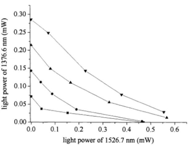
0.6 light power of 1526.7 nm (mW)Fig. 6. Variation ofthe light power ofthe SWM to that ofthe LWM at wavelength separation of 150 nm. The wavelength positions ofthe two modes are the same as in Fig. 4 (c).
1527.8 nm, and thus 1527.8 nm has fewer carriers. This results in that 1527.8 nm has stronger "optical consumption
ability" of the short-wavelength photons. Therefore, LWM at 1527.8 nm will have less apparent anti-competition
behavior than LWM at 1527.8 nm under fixed wavelength separation, as shown in Fig. 5.
Sinceanti-competition is due to the physics similar to optical pumping, it can exist only at the LWM. For the
SWM, increasing the light power of the LWM will only decrease its light power, as shown in Fig. 6 for the same two modes as in Fig. 4 (c). Note that although both Fig. 4 (a) and Fig. 6 are curves with competition, their behaviors are different. For example, the curves in Fig. 4 (a) are curving downward, whereas those in Fig. 6 are curving upward.
3. ANALYSIS
Previous models of competition usually use the following rate equations to describe the gain saturation: [5]
d11 g10
—11
(la)
=( g20
_
)'2
(ib)
dt
1+S212+C1211 2where the first term in parentheses [Eq. (Ia)] represents the gain with self- and cross-saturation; gio and goarethe
unsaturated gains of the modes Ii and 12 ,respectively;ii and 12 are losses of the modes Ii and 12 ,respectively. In reality,
the denominators in Eqs. (la) and (ib) are not linear functions of Ii and 12 .Therate equations can be put into more general forms:
-
= [G1(I ,
'2 )1 ]J ,
(2a)112
[G (I ,
12)
— 12"2
'
(2b)with Gi(Ii ,12) and G2(J1 ,12) representing general relations of the gains and the intensities Ii and 12 .Inthe steady state, dli Idt=d12Idt=0.Equations (2a) and (2b) can then be written as
[Gi(Ii ,12)-l1]I1 =0, (3a)
[G2(I1 ,12)-12]12 =0, (3b)
where Gi(Ii ,12) -
ii
=0 and G2(I1 ,12) -12 0 represent two curves on the Ii— 12 phase plane.Let's define Ii and 12 as the intensity of the LWM and SWM, respectively. The saturation effect causes the gain to decrease with the intensity, so the self-saturation leads to G2
I
12<
0.The competition is due to cross-saturation [2,3], so a G2 1Ii
<
0.Thus, for competition situation, the gain curve G 2(Ii,
12) -
12 0 should have the slope dli I d12<
0,which is the case for Fig. 4 (a) and for previous experiments [2,6]. For the case of anti-competition shown in Fig.4 (b)—{d), dli Id12>0.Because self-saturation still gives 3 G2 I 812 <0,it must be that G2
I
Ii
>0.As a result, the power-series expansion of G2 (Ii ,12) consists of a term ( 0 G2 I Ii )Ii (y Ii
>0),which means the condition likeoptical pumping. That is, the short-wavelength mode gives away its optical power to the long-wavelength mode.
However, the two-mode operation is not exactly the same as optical pumping. As shown in Fig. 4 (b)-(d), some regime of competition still exists, indicating that the cross-saturation plays an important role again for certain intensity of li.
4. CONCLUSION
Anti-competition of laser modes is observed in semiconductor laser with nonidentical MQWs. In this behavior, the oscillation intensity of the long-wavelength mode can be enhanced by that of the short-wavelength mode, which is opposite to the well-known mode competition. The phenomenon of anti-competition can be observed as long as the wavelength separation is larger than 1 1 1 nm, and is even more prominent for wavelength separation up to 1 68 nm. The influential factors of anti-competition includes the wavelength separation, the power of both modes and the wavelength position. Theoretical analysis shows that anti-competition is due to the physics similar to optical pumping.
REFERENCES
[1] W. E. Lamb, "Theory of an optical maser," Phys. Rev. A 134,1429(1964) [2] A. E. Siegman, Lasers (University Science Books, 1986).
[3] K. Shimoda, Introduction to Laser Physics (Springer, Berlin, 1984), p.187.
[4] M. Watanabe, H. Itoh, S. Mukai, and H. Yajima, "Optical tristability using a twin-stripe laser diode," Appi. Phys. Lett. 50, 427 (1987).
(c661)
8T
'1S1UOJ/
wnuvn
uz S7dOJpapa/as
Joivulnor
¶:q:qI'uijdnoo
!q1o-uds tP!M SJOS IPM-WmUnbpouis
jo
uijopoy,,
'unqj
j
pu
utqj
s-[i1
¶:I
T
wnuvn3
•uo43iq
'9Zi
(o661)'&!!x!w puiq OUOj1A 4TM