Mode Detection, Synchronization, and Channel Estimation for DVB-T OFDM
Receiver
Shiou-Hong Chen Way-Hong He Hou-Shin Chen Yumin Lee
Graduate Institute of Communication Eng. and
Department of Electrical Eng.,
National Taiwan University, Taipei 10617, Taiwan
Abstract – A baseband receiver for DVB-T OFDM withvariable number of subcarriers is presented in this paper. The proposed receiver consists of a blind mode detector, time and frequency synchronizer, and channel estimator. The blind mode detector uses a novel algorithm to detect the number of OFDM subcarriers in the received signal. Time and frequency synchronization is performed after the transmission mode is detected. Finally, channel estimation is performed using 1D or 2D interpolation. Simulation results show that the proposed mode detection and synchronization algorithms are close to ideal, and good overall performance is achievable.
I. INTRODUCTION
Terrestrial Digital Video Broadcasting (DVB-T) is a next-generation standard for wireless broadcast of MPEG-2 video [1]. In order to provide the high data rate required for video transmission, concatenated-coded orthogonal frequency division multiplexing (OFDM) has been adopted into DVB-T. In order to cope with a multitude of propagation conditions encountered in the wireless broadcast channel, many parameters of OFDM for DVB-T can be dynamically changed according to channel conditions. In particular, the number of OFDM subcarriers can either be 2048 (2K) or 8196 (8K) so that the desired trade-off can be struck between inter-symbol interference (ISI) mitigation capability and robustness against Doppler-spread [1][2]. As a result, a “mode detector” that detects the number of subcarriers in the transmitted OFDM symbol is required in a DVB-T receiver. Furthermore, time and frequency synchronization as well as channel estimation are also required as in any OFDM transmission system. Note that these operations can be performed and the transmitted information detected only after the correct number of subcarriers has been determined. Therefore mode detection must be done prior to synchronization and channel estimation in a DVB-T receiver. In principle, mode detection can be carried out by detecting the positions of pilot subsymbols. However, this method requires the knowledge of the pilot pattern and is therefore system-dependent. In this paper, a new algorithm is proposed for blind mode detection. The proposed algorithm exploits the cyclic nature of OFDM signals and difference in symbol durations to distinguish between different numbers of subcarriers. It will be shown in this paper that the proposed algorithm is simple and effective. Furthermore, since pilot subsymbols are not required, the proposed method is system-independent
and is applicable to any OFDM system with variable number of subcarriers.
In this paper, we also propose time and frequency synchronization and channel estimation algorithms that are performed after the transmission mode is detected and can be easily integrated with the blind mode detection scheme. Simulation results show that the proposed receiver can achieve very good overall performance.
II. SYSTEM SPECIFICATIONS
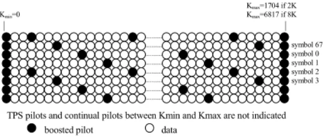
Although DVB-T allows flexible choice of many transmission parameters, in this paper we assume that the DVB-T transmitter uses OFDM with 16-level quadrature amplitude modulated (16 QAM) subcarriers. The
number of subcarriers can be N1 = 2048 (2K mode) or N2
= 8192 (8K mode). For both 2K and 8K modes, scattered pilots and continual pilots are present in the OFDM symbols as shown in Fig. 1. For 2K (8K) mode,
the useful part of an OFDM has a duration of TU =224
(896) µs (values for 8MHz channels). The length of the
cyclic prefix (CP) is assumed to be 0.125TU, therefore the
number of CP samples (chips) in an OFDM symbol is ∆1 =
256 and ∆2 = 1024.
The OFDM signal is transmitted to the receiver via the wireless channel, which is assumed to be a multipath Rayleigh fading channel corrupted by additive white Gaussian noise (AWGN). The multipath fading channel is modeled using the modified Jakes’ fading model [8] with a carrier frequency of 500MHz. At the receiver, the receiver signal is first downconverted to the baseband, filtered and sampled, and processed by the proposed receiver to be discussed in the next section.
III. PROPOSED RECEIVER
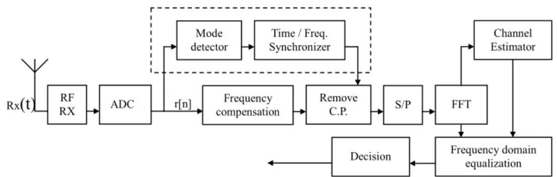
Figure 2 shows the block diagram of the proposed DVB-T receiver. The received signal is first processed by the RF front-end and analog-to-digital converter (ADC)
Kmax=1704 if 2K Kmin=0 Kmax=6817 if 8K | | symbol 67 symbol 0 symbol 1 symbol 2 symbol 3
TPS pilots and continual pilots between Kmin and Kmax are not indicated boosted pilot data
Fig. 2. Block diagram of the proposed DVB-T receiver. and fed into the blind mode detector and time/frequency
synchronizer to determine the transmission mode (2K or 8K), optimal timing, and carrier frequency offset. The CP is next removed and the resulting signal is serial-to-parallel (S/P) converted and transformed into the frequency domain using fast Fourier transform (FFT). Channel estimation and frequency-domain equalization are next performed, and the transmitted symbols are then detected using the decision device.
A. Blind Mode Detection and Synchronization
The purpose of blind mode detection is to determine the number of subcarriers in an OFDM symbol. In the proposed receiver, this is accomplished by exploiting the cyclic nature of OFDM symbols. Mathematically, define the autocorrelation function of the received OFDM signal as
[ ]
∑
−[
] [
]
= − − − = 1 0 * 1 NiQ j i i in N rn jr n j N x (1)where Ni is the number of subcarriers of the i-th mode and
Q is an integer. As shown in Figure 3, due to the cyclic
nature of OFDM symbols, when there is no noise,
periodic peaks can be observed in xi[n] only when Ni is set
to the correct value [4]. Using an incorrect value of Ni
results in a noise-like xi[•]. It can be argued from Figure
3 that the correct mode can be detected by examining the
relative dynamic range of xi[•]. We therefore define the
variation-to-average ratio as
[ ]
[ ]
[ ]
n x n x n x M i i i i 2 2 − = , (2)where <> denotes time-averaging over a number of samples. The transmission mode can then be detected as
i i M
iˆ =argmax (3)
After the transmission mode is detected, time and frequency synchronization are next performed. In the proposed receiver, the boundary between successive OFDM symbols is first acquired using the time synchronization algorithm. It can be seen from Figure 3
that the autocorrelation function xi[n] defined in (1) for
blind mode detection can also be exploited for time synchronization. In the proposed receiver, we first compute an average autocorrelation function defined as
Fig. 3 Examples of correlation output amplitude for (a) 8K-mode transmitted, frequency-flat channel. (b) 2k-mode transmitted, frequency-flat channel. (c) 8k-mode transmitted, frequency-selective channel.
[
]
∑
− = − ≡ 1 0 ˆ ˆ 1 ] [ L l i i n lN x L n x , (4)where L is the number of observed OFDM symbols. Assuming that the received signal has been frame-synchronized, the optimal timing (sample index of the beginning of the first OFDM symbol) is given by
δ − ≡ < ≤ [ ] max arg ˆ 0 0 x n n i N n , (5)
where the integer δ is a margin that is empirically
determined to reduce the sensitivity of the method. After the optimal timing is determined, the frequency offset is next estimated and compensated using a three-step frequency synchronization algorithm. Assuming that the frequency offset between the transmitter and receiver oscillators is given by
U T b K f =( + ) 1 ∆ , (6)
where K is an integer and –0.5 ≤ b < 0.5. It can be easily
verified that, when there is no noise, the phase difference between a sample in the cyclic prefix of a received OFDM
symbol and the sample TU seconds later is roughly –2πb.
Therefore an estimate for b is given by
[ ]
(
0)
0 Arg 2 1 n x b π − ≡ , (7) r[n] Rx(t)
RX RF ADC Remove C.P. FFT Channel Estimator Frequency domain equalization Time / Freq. Synchronizer Mode detector Decision S/P Frequency compensationwhere Arg(x) is the phase angle (modulo 2π) of x. On the other hand, K can be estimated by making use of the continual pilots. Specifically, let R(j, k) be the received subsymbol of the j-th OFDM symbol at the k-th subcarrier, and define the average correlation coefficient
2 0 2 0 0 * 0 0 ) , ( ) , 1 ( ) , ( ) , 1 ( ) ( k k j R k k j R k k j R k k j R k p p p p + + + + + + ≡ ρ , (8)
where <> denotes averaging over the continual pilot
subcarrier index kp. It can be easily argued that, when
there is no noise, ρ(k0) is maximized when k0 = K.
Therefore a reasonable estimate for K is given by
( )
0 0 0 max k K k ρ ≡ (9)The estimated frequency offset is then given by
(K0+b0)/TU Hz.
Preliminary simulations show that when b ≈ 0.5,
separately using (7) and (9) for frequency offset estimation may result in poor performance in the presence
of noise. For example, if K + b = 2.45 and K0 = 3, then
the error in K0 cannot be completely compensated because
b0≥ −0.5. In order to solve this problem, in the proposed
receiver frequency synchronization is done in three steps.
In the first step, (7) is evaluated to obtain an estimate b0.
The received signal is then frequency-compensated by
b0/TU Hz to make the residual frequency offset
approximately equal to a multiple of the carrier spacing. In the second step, (9) is evaluated to obtain an estimate
K0, and the received signal is frequency-compensated by
K0/TU Hz. Finally, (7) is evaluated again to recover the
remaining frequency offset. B. Channel Estimation
The purpose of channel estimation is to find an estimate )
, (
ˆ jk
H for the complex channel gain experienced by the
transmitted subsymbol in the j-th OFDM symbol at the
k-th subcarrier. In the proposed receiver, this estimation
is done by first estimating gains at the scattered pilots and then interpolating between OFDM symbols and subcarriers. In DVB-T, scattered pilot subsymbols in the
j-th OFDM are available at kp=12l+3(j–1), where l =
0,1,2,…, as shown in Figure 1. Assuming that a pilot
subsymbol X(j, kp) is transmitted in the j-th OFDM
symbol at the kp-th subcarrier, the corresponding channel
gain estimate is given by
( )
( )
p p p k j X k j R k j H , , ) , ( ˆ ≡ . (10)The gains at all other subcarriers are then obtained by interpolating the gains in (10) using various methods discussed as follows.
B.1 1D Interpolation
In this method, pilot subsymbols from four successive OFDM symbols are first grouped together to provide channel gain estimates at every third subcarrier in every OFDM symbol. Mathematically, we first define
( ) + − + − = ≡ else , 0 3 if , , 2 4 mod ) 3 ( ˆ ) , ( ~ jk H j l j k k l H
.
(11)Channel gain estimates Hˆ(j,k) at other (non-pilot)
subsymbols are then obtained fromH~(j,k)by interpolation.
The interpolation algorithms investigated in this paper include:
1) Linear interpolation [6], in which
+ + − ≡ 3 3 3 , ~ 3 3 mod 3 3 , ~ 3 3 mod 1 ) , ( ˆ jk k H j k k H j k H (12)
where x denotes the integer part of x;
2) Sinc interpolation[7], in which Hˆ(j,k) are
interpolated from H~(j,k)using discrete-time sinc
functions; and
3) Regularized least-squares (LS) interpolation, in which the regularized LS estimate of the time-domain channel impulse response is computed based on
) , ( ~ k j
H and transformed into the frequency domain
using DFT. Mathematically, let
[
]
T N j H j H j H~( ,0) ~( ,3) ~( , −1) ≡ L H . (13)We first find hˆthat minimizes
(
2 2 2)
min arg ˆ h H Wh h h + − ≡ σ (14)where σ2 is the regularization constant, W is a partial
DFT matrix so that H = Wh when there is no noise and h is the correct time-domain channel response.
B.2 2D Interpolation
In 2D interpolation, channel gain estimates at scattered pilot subsymbols are first interpolated over time so that
channel gain estimates H~(j,k) are available at every
third subcarrier in every OFDM symbol. Channel gain
estimates Hˆ(j,k) at all other subsymbols are then
obtained from H~(j,k) by interpolation as in 1D
interpolation. Note that the primary difference between
1D and 2D interpolation is in the way H~(j,k) is
obtained.
IV. SIMULATION RESULTS
A. Blind Mode Detection
The performance of the blind mode detector is shown in Figure 4 in which the mode detection error rate (MER) is
shown as a function of Eb/N0, where Eb is the energy per
channel bit and N0/2 is the two-sided power spectral
density of the AWGN. Only the 2K mode is simulated because it has a higher MER. Here the channel is assumed to be a frequency-flat Rayleigh fading channel. The time-average in (1) is taken over 81920 samples, while Q=32. It can be seen from this figure that the proposed blind mode detection algorithm is extremely reliable. In particular, error-free detection can be
achieved when Eb/N0 > 0dB. Since Eb/N0 must be
significantly larger than 0dB for the rest of the system to work, it can be concluded that the effect of mode detection error on overall performance is negligible when the proposed detection algorithm is used.
Fig. 4. Mode detection error rate as a function of Eb/N0.
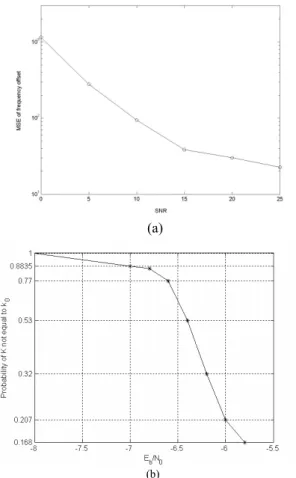
B. Time and Frequency Synchronization
The performance of time and frequency synchronizer is shown in Fig. 5. Here the channel is a Rayleigh multipath fading channel with exponential power delay profile and root mean-square (RMS) delay-spread of 5.2 µs. Only 2K mode is simulated and mode detection is assumed to be perfect. Fig. 5(a) shows the mean-square error (MSE) of the proposed frequency offset estimation algorithm as a
function of Eb/N0 when the carrier frequency offset is
roughly 3.44 subcarrier spacings (approximately 23 ppm of the carrier frequency). It can be seen that the RMS value of the estimation error is on the order of a few tens of Hz, or roughly 1% of the subcarrier spacing. In Fig.
5(b), Prob[K ≠ K0] is plotted as a function of Eb/N0. It
can be seen that this probability decreases rapidly with
Eb/N0. Although not shown in the figure, when Eb/N0 > -5
dB this probability is negligible. Since the estimated
frequency offset is given by (K0+b0)/TU, it can be inferred
from Fig. 5 that the proposed algorithm yields very accurate estimate for b. Furthermore, since time and frequency synchronization are intimately related by (7), it can therefore be further inferred that the proposed time synchronization algorithm also yields very accurate timing information.
C. Channel Estimation
The Performance of the proposed channel estimators in a Rayleigh multipath fading channel with exponential power-delay profile and RMS delay spread of 5.2 µs are shown in Figs. 6. Only the 2K mode is simulated. Mode detection and time and frequency synchronization are assumed to be ideal. In Fig. 6(a), the channel bit error rate (BER) of 1D interpolation channel estimators are shown as functions of C/N, where C/N is defined as the ratio of transmitted energy per subsymbol to the complex noise variance of the received subsymbols. The channels are assumed to be stationary within an OFDM symbol. It can be seen that regularized LS interpolation and sinc interpolation have similar performance, and both outperform linear interpolation at high C/N. This is because linear interpolation has a large interpolation error that results in a BER floor at high C/N.
(a)
(b)
Fig.5. The performance of time and frequency synchronizer. Fig. 6(b) shows the performance of the 1D and 2D interpolation estimators in a fast fading environment.
Here we have fmTU=0.05, where fm is the maximum
Doppler shift frequency. For both 1D and 2D interpolation estimators, regularized LS interpolation and linear interpolation are chosen for frequency-domain interpolation, while the 2D interpolation estimators also use sinc or linear interpolation in the time domain. It can be seen that 2D interpolation significantly outperforms 1D interpolation as one would expect. Furthermore, it can also be seen that the method used for time-domain interpolation does not affect performance, while using regularized LS interpolation in the frequency domain results in a slightly better performance.
D. Overall Performance
Fig. 7 shows the overall BER performance of the combination of the proposed blind mode detection, synchronization, and channel estimation methods. The channel is a Rayleigh multipath fading channel with exponential power-delay profile and RMS delay spread of 5.2 µs, and the carrier frequency offset is 10KHz (20ppm of the carrier frequency).The transmission mode is 2K. 2D interpolation with regularized LS frequency-domain interpolation and linear time-domain interpolation is used for channel estimation. Performance of a receiver with perfect mode detection and synchronization is also shown
for fm=0. The curve labeled as “ideal” is the
5 1 0 1 5 2 0 25 3 0 10-3 10-2 1 0-1 C /N (d B ) BER L ine a r S inc Re g ula rize d L S P erfe ct channe l knowle d g e
(a) 5 1 0 15 20 25 30 10-3 10-2 10-1 C /N (d B ) BER L ine a r 1 D Re g ula rize d L S 1 D L ine a r(fre q .) D F T(tim e .) L ine a r(fre q .) L ine a r(tim e .) Re g . L S (fre q .) D F T(tim e .) Re g . L S (fre q .) L ine ar(tim e .)
(b)
Fig.6 Performance of the channel estimators in a Rayleigh multipath fading channel: (a) 1D estimator for DVB-T 2K mode (b) 1D and 2D
estimator in a fast fading environment.
synchronization, and channel estimation. It can be seen that when the proposed algorithms are used, the effect of mode detection error and synchronization error on
performance is insignificant for fm=0. Furthermore, the
2D interpolation channel estimator achieves a performance that is roughly 2dB away from the ideal case. On the other hand, by comparing to Fig. 6, it can again be seen that the effect of mode detection error and synchronization error on performance is insignificant for
fmTU = 0. Therefore, the overall performance is dominated
by channel estimation accuracy. V. CONCLUSIONS
An OFDM receiver for DVB-T is proposed and analyzed by simulation in this paper. In the proposed receiver, a new blind algorithm is first used for detecting the number of OFDM subcarriers in the received signal. The received signal is then synchronized in time and frequency. Channel estimation is next performed using the pilot subsymbols and 1D or 2D interpolation. Simulation results show that the proposed blind mode detection and synchronization algorithms can achieve almost ideal performance. The overall performance is roughly 2dB away from the ideal performance, and is dominated by channel estimation error.
5 1 0 1 5 2 0 2 5 3 0 1 0-3 1 0-2 1 0-1 C /N (d B ) BER f mTU=0 .0 5 fmTU=0 id e a l m o d e d e te ctio n & syn. fmTU=0 id e a l
Fig.7 Performance of the proposed DVB-T receiver REFERENCES
[1] ETSI, “Digital Video Broadcasting: Framing Structure, Channel coding, and Modulation for Digital Terrestrial Television”, European Telecommunication Standard EN300744, Aug. 1997.
[2] A. Garci´a Armada, M. Calvo, L. de Haro, "Influence of the subcarrier spacing in the performance of an OFDM communication system", Proc. HDTV'97, Montreux, Switzerland, pp.C1-C4, 1997
[3] Hlaing Minn and Vijay K. Bhargava, “An Investigation into Time-Domain Approach for OFDM Channel Estimation,”
IEEE Transactions on broadcasting, vol. 46, no. 4, December 2000.
[4] Richard van Nee, Ramjee Prasad, OFDM for Wireless
Multimedia Communications, Artech house, 2000.
[5] A.A. Hutter, R. Hasholzner, J.S. Hammerschmidt, “Channel Estimation for Mobile OFDM Systems,” IEEE
International Vehicular Technology Conference, 1999. [6] Fabrizio Frescura, Stefan Pielmeier, Gianluca Reali,
Giuseppe Baruffa, Saverio Cacopardi ,”DSP Based OFDM Demodulator and Equalizer for Professional DVB-T Receivers,” IEEE Transactions on broadcasting, vol. 45, no. 3, December 1999.
[7] M. Garcia, J. Paez-Borrallo, S. Zazo, “DFT-Based Channel Estimation in 2D-Pilot-Symbol-Aided OFDM Wireless Systems,” IEEE Vehicular Technology Conference, 2001. [8] P. Dent, G.E. Bottomley, and T. Croft, Jakes fading model
revisited,” Electronics Letters, vol.29, no.13, pp.1162-1163, June 1993.