Modified TMN8 Rate Control for Low-Delay Video Communications
9
0
0
全文
(2) in the same order of coding; i.e., in a raster scan order (from left to right, then top to bottom). Our investigation indicates that the more complex MBs introduce more distortion, thus should be encoded before less complex ones. Based on the concept, we present a modified TMN8 in which the coding order is to favor the more complex MBs. However, the output sequence of a bitstream follow the raster scan order; thus the codec is fully compliant to the H.263 standard. The results indicate that the new scheme achieves average PSNR gain of 0.8 dB over TMN8. In addition, the buffer occupancy is steadier and average bit rate achieved is closer to the target channel rate. This paper is organized as follows. In the following section, we review the TMN8 rate control technique. The modification of TMN8 is then described in Section III. In Section IV, the experiments are conducted to evaluate the performance of the algorithm. Finally, the concluding remarks are provided in Section V.. where W W > 0.1 ∗ R / F , ∆= F W − 0.1 ∗ R / F , otherwise. The rate-control scheme used in TMN8 was designed for low-delay video communications [1]. The goal is to encode good quality video for transporting over a constant bit-rate channel and maintain a low buffer delay. The TMN8 rate control uses frame-layer rate control to select a target bit count for the current frame, and a macroblock-layer rate control to select the values of the quantization step-sizes for the macroblocks in the frame. A frame is skipped if the number of bits accumulated in the buffer after encoding the previous frame is greater than a limit. In the frame-layer rate control, the frame bit-budget varies according to the buffer fullness, the frame rate and the channel rate. Before encoding the current frame, the number of bits in the encoder buffer (buffer fullness) is calculated by (1). where D =the actual number of bits used for encoding the previous frame, Wprev= the previous number of bits in the buffer R= channel rate F= frame rate If W is larger than the predefined threshold M=R/F, the encoder skips encoding frames until the buffer fullness is below the threshold.. (3). The macroblock-layer rate control selects the values of the quantization step-sizes for all the macroblocks in a frame on a MB-by-MB basis. It is performed in a raster scan order (left to right then top to bottom). The optimal quantization step-size Q *i for the ith MB is derived using rate-distortion model and represented as Qi* =. 256 Ki σ i Si Li α i. (4). where σi is the standard deviation of the ith MB. Si =. II. TMN8 Rate Control. W=max(Wprev+D-R /F , 0). The frame bit-budget for the current frame is estimated as R BT = − ∆ (2) F. N. ∑ α k σ k is the weighted (with weight αk). k =i. energy sum of the remaining MBs at time unit i (MBs 1 to i-1 have been encoded). Li= β i - 256NiCi is the number of bits left for encoding the remaining MBs excluding overhead bits. The MB-layer rate control starts from the first MB. Calculating Q1 using Eq. (4) and encoding the MB, we have the coding bit-count of the MB. By subtracting the coding bit-count and the estimated header bit-count from the frame bit-budget, the remaining bit-budget is obtained. The procedure repeats for the second MB, the third MB, and so on, until all MBs are coded. The model parameters Ki and Ci are updated on a MB-by-MB basis. It is noted that the allocated quantization step-size of the current MB is dependent upon the remaining bit budget Li and complexity of the MB, σi. This implies that if the remaining bit budget is very low (may be zero sometimes), the current MB will be quantized very coarsely. Consequently, it will introduce more distortion.. III. Modified TMN8 Rate Control Algorithm In this section, we first discuss the relationship of quantization distortion and the coding order of MBs in a frame. Based on the relationship, a modified TMN8 rate control scheme is developed. 3.1 Relationship of Distortion and Coding Order The distortion in the ith macroblock is.
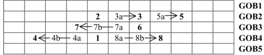
(3) introduced by quantizing its DCT coefficients with a uniform quantizer with step size Qi. The typical distortion measure of quantization is [1] D=. N. Qi2. i =1. 12. ∑αi2. (5). where N is the total number of macroblocks in a frame, and αi is the distortion weight of the ith macroblock. In current video coding standards, Qi=2 × QPi, where QP is the quantization parameter. Substituting the above equation into distortion function (4), we have D=. 256 N Ki α i σ i Si ∑ 12 i =1 Li. (6). It is obvious that the quantization distortion is proportional to the standard deviation σ of a MB. In other words, the higher complexity (larger σ ) of a MB, the more distortion will be introduced when the same quantization step size is used. The high complex MBs are more significant and should be quantized before low complex ones because of the following reason: y In low rate video coding standards such as H.263, the change of QPs of two adjacent MBs, DQUANT, is restricted within two levels. Thus, if the complexity of two adjacent MBs is greatly different, the restriction may result in the following two possible drawbacks. First, if the previous MB is low complex and the current MB is high, the previous QP (denoted as QPprev) will be small, so the current MB will be quantized too finely because its QP is limited to QPprev +2. Consequently, it will generate too much number of bits. This may result in the fact that the remaining bits are run out, and thus the remaining MBs should be quantized too coarsely. An alternative case is that the previous MB is high complex and the current MB is low. In this case, the QPprev will be large, so the current MB will be quantized too coarsely and significant distortion will be introduced. Based on the concept, the best manner is to sort the SAD values of all MBs in a frame in a descending order, and then encode the MBs in this order. However, it is necessary to send the ordering information to the decoder, which requires a large amount of overhead bits. Moreover, it violates the raster scan order in the typical video coding standards, which may decrease the coding efficiency of motion vectors with DPCM. To attack the problems, we develop an alternative scheme as follows. This scheme has the advantageous feature that the more complex MBs are encoded first while keeping the compatibility with the video coding standards.. 3.2 Modified TMN8 Rate Control Fig.1 shows the encoding order of the MBs in a QCIF frame. By performing motion compensation for all MBs in a raster scan order, we record motion vectors and SAD values of each MB. Then we sort the SAD values and denote the SAD order of each MB, with integer number, as shown in Fig.1. The number “1” represents the largest SAD, “2” the second largest SAD, and so on. According to the specification of H.263, in a GOB, the DQUANT (difference of quantization parameter QPs of two adjacent MBs ) is restricted to the values in (-2, -1, 1, 2); i.e., |DQUANT|=|QPk-QPk-1|≤ 2. In this work, the complex MBs should be coded first. If a particular MB of a GOB has been encoded (denoted as MBcoded), its QP is obtained. In such case, the QP values of the other MBs in the same GOB are restricted. To meet the restriction, the next coding MB should be the neighbor of MBcoded (right or left neighbor depending the location of the current MB). In other words, the coding order starts from the nearest neighbor of MBcoded to the current MB. We take an example shown in Fig.1 to further explain the new scheme. The MB “1” is coded first since it has the largest SAD. Its QP is calculated with Eq. (4) without any restriction because no MBs in GOB4 have been coded. Similarly, the MB “2” is coded next without any restriction. Normally, the following MB to be encoded is “3”. However, in the GOB of MB “3”, the MB “2” has been encoded. Thus the next coding MB should be “3a”, and then “3”, as indicated by an arrow. The QP value of MB “3a” is restricted by that of MB “2” within two levels, and the QP of MB “3” is restricted accordingly. Similarly, the next consideration for coding is “4”. But because MB “1” has been encoded, the coding order should be changed to : “4a”, “4b”, “4”. Repeat the above procedure until all MBs have been processed, we obtain the QPs of all MBs, the status of headers including COD, MCBPC, CBPY, MVD and codewords of MB data. These data are stored in a temporary memory, and finish the first pass of coding. Then we run the second pass which performs tasks: (a) re-encoding of headers including picture header, GOB header and MB header, and (b) packing and transmission of the bit stream. The modified TMN8 rate control algorithm is summarized as follows. Frame-layer rate control Step 1: Determine frame bit-budget of by BT=R/F-Picture_Header-GOB_Header..
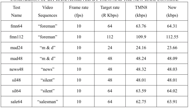
(4) Step 2: Calculate buffer fullness W using Eq. (1). Step 3: The bit budget for the current frame is updated by BT − 2 * (W / F ) if W > 0.5 ∗ ( R / F ) BT = BT + W − 0.5 ∗ ( R / F ) otherwise. Macroblock-layer rate control Initialization: Step 1: Clear quantization-parameter (QP)-table (set each entry of the table to zero). Step 2: Perform motion estimation and compensation for all MBs. For each MB, record its location, SAD, and motion vector. Sorting MBs according to the descending order of SAD values. Pass 1: Step 3(a): Select the next MB according to sorted order and denote it as MBcoding. Step 3(b): Search the MBs in the GOB that MBcoding locates to determine if any MB has been encoded. If the answer is no, determine Qi of MBcoding using Eq. (4) and encode the MBcoding and then go back Step 3(a). Otherwise, if there are MBs that have been coded, choose the coded MB that is nearest to MBcoding, and denote it as MBcoded. Step 3(c): The nearest neighbor of MBcoded that is closer to MBcoding is selected as the beginning of coding, denoted as MBstart. Encode all the MBs from MBstart to MBcoding using TMN8 scheme. Note that the QP value of the MBstart should follow the restriction of ±2 , relative to that of MBcoded. Go to Step 3(a). Notes: 1. During the encoding, we have to record QPs (QP=Qi/2) for all MBs on a QP table. If a MB is compensable, its QP is set to zero. In addition, the status of header codewords such as COD, MCBPC, CBPY, MVD, and bit stream of MBs should be stored into a temporary buffer. 2. The picture header and GOB header are not encoded in pass 1. Pass 2 Step 4(a): According to the status of the header of MBs and the records of the QP table, re-encode the header bits of MBs in a raster scan order. Step 4(b): Pack the newly generated headers, DQUANT, and the MB data into an encoded bit stream.. IV. Experimental Results We implemented the new rate control scheme and the TMN8 in a basic version of H.263 codec [13]. In this codec, the motion estimation is performed with full search algorithm (FSA) with 2:1 subsampling in both x and y directions for the concern of low computation. That is, a 16 x 16 MB is first reduced into 8 x 8 and then FSA is performed with search range of –15 to +15. The optional tools in H.263 such as advanced prediction (AP mode) and unrestricted motion vector were not implemented. Five QCIF test sequences, each with frame rate of 10 Hz and various target bit rates, are conducted. The first frame was intracoded (I frame) with QP=15, as in TMN8. The remaining frames were all intercoded (P frames) [1]. Table I shows the PSNR values of reconstructed pictures and the number of skipped frames. The former indicates the spatial quality, whereas latter the motion continuity (temporal quality). The new rate control achieves average PSNR gain about 1.05 dB. In addition, TMN8 skipped 5 frames for “mother and daughter” at 24 kbps. However, our algorithm does not skip any. The results indicate that our algorithm perform better than TMN8 both in spatial quality and temporal quality. Table II shows the actual bit rates achieved by TMN8 and the new algorithm. It indicates that the new algorithm achieves a bit rate closer to the target than TMN8 for most of sequences. Fig. 2(a) to Fig.2(c) show PSNR curves for various sequences. Obviously, our algorithm provides higher PSNR for most frames of a sequence. Figs. 3(a) to 3(c) show the number of bits in the buffer at each frame. The buffer overflow threshold is set to R/F in this work. If the buffer fullness is larger than the threshold, called overflow, both rate control schemes skip frames until it is below the threshold. For “mother & daughter” at 24 kbps, TMN8 overflows 5 times, which indicates the five frames are skipped. However, in the proposed algorithm, no overflow occurs for all sequences under various test conditions. It is found from these figures that the proposed algorithm achieves lower and steadier buffer fullness. This implies that the new algorithm produces lower and stable buffer delay. If the curve of the buffer fullness touches the x axis (zero line), it yields buffer underflow problem. In such case, the stuffing bits must be inserted into the bit stream. Although the underflow does not affect motion continuity, it wastes channel bandwidth. From these figures,.
(5) 4. 7 4a. 4b. 2 7b 1. 3a 7a 8a. 3 6 8b. 5a. 5. 8. GOB1 GOB2 GOB3 GOB4 GOB5. Fig. 1. An illustration of MB-layer rate control. we obverse that the underflow occurs far less frequently in our algorithm than in TMN8 Figs. 4(a) to 4(c) display the actual coding bit counts per frame. The bit counts generated by both techniques have no significant fluctuation.. V. Conclusions A modified version of TMN8 rate control has been presented in this paper. The modification mainly focuses on the coding order of macroblocks. We measure the complexity (significance) of all macroblocks. Then encode the macroblocks according to the order of significance while following the constraint of max|DQUANT|=2. The results indicate that the new scheme achieves average PSNR gain of 1.05 dB over TMN8. In addition, the buffer occupancy is steadier and average bit rate achieved is closer to the target channel rate.. Acknowledgment The authors greatly thanks for the support of the National Science Council, grant number is NSC 89-2213-E-214-091. References [1] ITU-T/SG15, Video codec test model, TMN8, Portland, June 1997. [2] ITU-T/SG16, Video codec test model, TMN10, Finland, Apr. 1998. [3] J. Ribas-Corbera and S. Lei, “Rate control in DCT video coding for low-delay video communication,” IEEE Trans. Circuits Syst. Video Technol.,vol. 9, pp. 172–185, Feb. 1999. [4] H. Song and C.-C. Jay Kuo, “Rate control for low-bit-rate video via variable-encoding frame rates,” IEEE Trans. Circuits Syst. Video Technol.,vol. 11, pp. 512–521, Apr. 2001.. [5] H. J. Lee, T.H Chiang, and Y.Q. Zhang, “ Scalable rate control for MPEG-4 video,” IEEE Trans. Circuits Syst. Video Technol.,vol. 10, pp. 878-894, Sept. 2000 [6] Coding of Moving Pictures and Audio, MPEG4 video VM—Version 18, ISO/IEC JTC1/SC29/WG11/ N3908, Pisa, Jan. 2001. [7] S. W. Wu and A. Gersho, “Rate-constrained optimal block-adaptive coding for digital tape recoding of HDTV,” IEEE Trans. Circuits Syst.Video Technol., vol. 1, Mar. 1991. [8] K. Ramchandran, A. Ortega, and M. Vetterli, “Bit Allocation for dependent quantization with applications to multiresolution and MPEG video coders,” IEEE Trans. Image Processing, vol. 3, pp. 533–545, Sept. 1994. [9] A. Ortega, K. Ramchandran, and M. Vetterli, “Optimal trellis-based buffered compression and fast approximations,” IEEE Trans. Image Processing, vol. 3, pp. 26–40, Jan. 1994. [10] J. Choi and D. Park, “A stable feedback control of the buffer state using the controlled Langrange multiplier method,” IEEE Trans. Image Processing, vol. 3, pp. 546–558, Sept. 1994. [11] L. J. Lin and A. Ortega, “Bitrate control using Piecewise approximated ratedistortion characteristics,” IEEE Trans. Circuits Syst. Video Technol., vol. 8, pp. 446–459, Aug. 1998. [12] T. Chiang and Y.-Q. Zhang, “A new rate control scheme using quadratic rate distortion model,” IEEE Trans. Circuits Syst. Video Technol., vol.7, pp. 246–250, Feb. 1997. [13] Video Coding for Low Bitrate Communication, ITU-T Recommendation H.263 Version 2, Jan. 1998..
(6) TABLE I COMPARISON OF THE NUMBER OF FRAME SKIPPED AND AVERAGE PSNR FOR TMN8 AND NEW RATE CONTROL IN THE H263 CODEC Test. Total. TMN8. New. TMN8. New. Gain in. Name. Frames. #Frames. #Frames. PSNR dB. PSNR dB. PSNR dB. Skipped. Skipped. fmn64. 100. 0. 0. 29.82. 30.06. +0.24. fmn112. 100. 0. 0. 32.41. 32.59. +0.18. mad24. 100. 5. 0. 31.31. 32.10. +0.79. mad48. 100. 0. 0. 34.78. 35.65. +0.87. news48. 100. 0. 0. 31.96. 32.71. +0.75. sil48. 100. 0. 0. 31.25. 32.90. +1.65. sil64. 100. 0. 0. 32.83. 34.98. +2.15. sale64. 100. 0. 0. 34.90. 36.70. +1.80. When frames were skipped, the respective previous reconstructed frames were used in PSNR computation. The PSNR is calculated in terms of the luminance component. TABLE II COMPARISON OF BIT-RATE ACHIEVED BY TMN8 AND THE NEW RATE CONTROL Test. Video. Frame rate. Target rate. TMN8. New. Name. Sequences. (fps). (R Kbps). (kbps). (kbps). fmn64. “foreman”. 10. 64. 63.76. 64.31. fmn112. “foreman”. 10. 112. 109.9. 112.55. mad24. “m & d”. 10. 24. 24.16. 23.66. mad48. “m & d”. 10. 48. 48.24. 48.09. news48. “news”. 10. 48. 48.32. 48.03. sil48. “silent”. 10. 48. 48.01. 48.01. sil64. “silent”. 10. 64. 63.59. 64.02. sale64. “salesman”. 10. 64. 62.75. 63.91.
(7) PSNR for Foreman (R=112 k, F=10 fps) Average PSNR(TMN8)=32.41 dB Average PSNR(NEW)=32.59 dB 36. PSNR (dB). 35 34. TMN8. 33. NEW. 32 31 30 1. 11. 21. 31. 41. 51. 61. 71. 81. 91. Frames. Fig. 2 (a) PSNR for Salesman (R=64 k, F=10 fps) Average PSNR(TMN8)=34.90 dB Average PSNR(NEW)=36.70 dB. PSNR(dB). 40. TMN8. 35. NEW 30. 25 1. 11. 21. 31. 41. 51. 61. 71. 81. 91. Frames. Fig. 2 (b). PSNR(dB). PSNR for Silent (R=48 k, F=10 fps) Average PSNR(TMN8)=31.25 dB Average PSNR(NEW)=32.90 dB 36 35 34 33 32 31 30 29 28. TMN8 NEW. 1. 11. 21. 31. 41. 51. 61. 71. 81. 91. Frames. Fig. 2 (c) Figs. 2 (a)-2(c). Comparison of PSNR performance for TMN8 and new algorithm.
(8) Buffer Fullness for Mother & Daughter (R=24 k, F=10 fps) Maxmum Bits for Overflow=2458 bits 3000 2500. Bits. 2000. TMN8. 1500. NEW. 1000 500 0 1. 11. 21. 31. 41. 51. 61. 71. 81. 91. Frames. Fig. 3(a) Buffer Fullness for Salesman (R=64 k, F=10 fps) Maxmum Bits for Overflow=6554 bits 5000. Bits. 4000 3000. TMN8. 2000. NEW. 1000 0 1. 11. 21. 31. 41. 51. 61. 71. 81. 91. Frames. Fig. 3 (b) Buffer Fullness for Foreman (R=48 k, F=10 fps) Maxmum Bits for Overflow=4915 bits 6000 5000. Bits. 4000. TMN8. 3000. NEW. 2000 1000 0 1. 11. 21. 31. 41. 51. 61. 71. 81. 91. Frames. Fig. 3 (c) Figs. 3(a)-(c). Comparison of buffer fullness for TMN8 and new algorithm. Dotted line indicated the threshold used for frame skipping..
(9) Coding Bits for Foreman (R=64 k, F=10 fps) Average Rate Control(TMN8)=63.76 k Average Rate Control(NEW)=64.31k 14500. Bits. 12500 10500. TMN8. 8500. NEW. 6500 4500 1. 11. 21. 31. 41. 51. 61. 71. 81. 91. Frames. Fig. 4 (a) Coding Bits for Silent (R=64 k, F=10 fps) Average Rate Control(TMN8)=63.59 k Average Rate Control(NEW)=64.02 k. Bits. 11000. TMN8. 9000. NEW 7000 5000 1. 11. 21. 31. 41. 51. 61. 71. 81. 91. Frames. Fig. 4 (b) Coding Bits for News (R=48 k, F=10 fps) Average Rate Control(TMN8)=48.32 k Average Rate Control(NEW)=48.03 k 16000 14000 Bits. 12000. TMN8. 10000. NEW. 8000 6000 4000 1. 11. 21. 31. 41. 51. 61. 71. 81. 91. Frames. Fig. 4 (c) Figs. 4 (a)-(c). Comparison of actual coding counts for TMN8 and new algorithm.
(10)
數據
相關文件
• A put gives its holder the right to sell a number of the underlying asset for the strike price.. • An embedded option has to be traded along with the
• Last data pointer stores the memory address of the operand for the last non-control instruction. Last instruction pointer stored the address of the last
– Taking any node in the tree as the current state induces a binomial interest rate tree and, again, a term structure.... Binomial Interest Rate
Before the frame start specified in PMC_RSP, the MS shall transmit PMC_REQ in response to receipt of an PMC_RSP from the BS directing a change to uplink power
– at a premium (above its par value) when its coupon rate c is above the market interest rate r;. – at par (at its par value) when its coupon rate is equal to the market
– Change Window Type to Video Scene Editor – Select Add → Images and select all images – Drag the strip to the “1st Frame” in Layer
Depending on the specified transfer protocol and data format, this action may return the InstanceID of an AVTransport service that the Control Point can use to control the flow of
One, the response speed of stock return for the companies with high revenue growth rate is leading to the response speed of stock return the companies with
