國
立
交
通
大
學
網路工程研究所
碩
士
論
文
在 IEEE 802.16(d) 網狀網路上利用網路編
碼技術提升一對一資料流的傳輸效能
Network Coding for Unicast Flows over IEEE 802.16(d)
Mesh Networks
研 究 生:張玉奇
指導教授:王協源 教授
在 IEEE 802.16(d) 網狀網路上利用網路編碼技術
提升一對一資料流的傳輸效能
Network Coding for Unicast Flows over IEEE 802.16(d) Mesh Networks
研 究 生:張玉奇 Student:Yu-Chi Chang
指導教授:王協源 Advisor:Shie-Yuan Wang
國 立 交 通 大 學
網 路 工 程 研 究 所
碩 士 論 文
A ThesisSubmitted to Institute of Network Engineering College of Computer Science
National Chiao Tung University in partial Fulfillment of the Requirements
for the Degree of Master
in
Computer Science
June 2007
Hsinchu, Taiwan, Republic of China
致謝辭
首先,感謝我的指導老師 王協源教授在我這兩年的求學過程中,提供一個 良好的學習環境,讓我能不斷累積研究及實務上的經驗而成長茁壯。老師在研究 領域之外也常常和我們分享日常生活的經驗,讓我獲益匪淺。另外,感謝兩位博 士班學長—周智良與林志哲,在學長的帶領下,我學習到很多團隊合作及系統開 發上的經驗,並且在論文的撰寫過程中給了我很多的幫助與建議,使我能順利的 完成這份論文。此外感謝撥冗擔任本篇論文口試委員的三位教授,你們珍貴的建 議使我的論文能更加充實而完整。 再來,我要感謝我的父母及家人,默默在背後支持我,讓我可以無後顧之憂 的專注於研究學習,在我的學習生涯裡,你們總是最關心我鼓勵我的一群,我也 希望這篇論文—也是我努力的一點成果可以與你們分享。 最後,在實驗室的日子裡,感謝每一位實驗室伙伴,當我遇到難題時總是可 以跟你們一起討論,努力之餘也有你們可以相約一起運動來抒解壓力,謝謝你們 讓我的研究生活能夠更加充實且多采多姿。中文摘要
網路編碼技術利用對網路封包作加密及解密的動作來提升網路傳輸的效 能。而網路編碼技術可以簡略分成兩個方向:intra-session 及 inter-session coding, 在這篇論文裡,我們將重點放在 inter-session coding,由於 inter-session coding 是 針對不同的一對一資料流來做編碼,所以比起 intra-session coding 的困難度相對 提高。 這篇論文與之前網路編碼的理論分析研究大不相同,我們提出一個容易實作 及佈建的機會式網路編碼架構並建構在 IEEE 802.16(d) 網狀網路上。不同於其他 研究者提出的實作架構,我們的系統只需要路由層及媒體存取控制層的相關資訊 即可發現編碼機會,而不需要額外的網路協定。由於這項優勢,我們的系統可以 輕易的架構在真實世界的網路上而不需大幅的修改。 除此之外,我們指出了一項新的“延伸的隱藏終端點問題",這個問題在使 用網路編碼的網路中會很容易發生,然而,在目前常用的無線網路標準裡無法避 免這個問題,所以我們提出一個頻寬保留的機制去避免此問題的發生,而這個機 制是由原本 IEEE 802.16(d) 網狀模式的三方交握機制去延伸而得。我們的模擬結 果展現了在應用層效能上網路編碼技術比起原本的路由機制大幅提昇,而且我們 提出的頻寬保留機制可以顯著地減少延伸的隱藏終端點問題的發生及封包碰撞 的次數。 關鍵字:無線網狀網路,網路編碼,IEEE 802.16,WiMAX,延伸的隱藏 終端點問題
ABSTRACT
Network coding is a packet-encoding-decoding mechanism that aims to increase the data transmission efficiency of a network. The development of network coding can be roughly classified into two categories: intra-session and inter-session cod-ing. In this thesis, we focus on the inter-session network coding because it is more challenging to improve the performances of multiple unicast flows.
Unlike other theoretical studies, we propose an implement and easy-to-deploy network coding scheme that is based on the opportunistic approach over IEEE 802.16(d) mesh networks. As compared with previous opportunistic coding scheme, our proposed scheme need not employ an additional protocol to find cod-ing opportunities or codcod-ing structures. Instead, only the routcod-ing and MAC-layer information are needed in our coding scheme. Using this advantage, it is easier to be realized in a real-life network as compared with the previously-proposed oppor-tunistic coding schemes.
In addition, in this thesis we point out a new “extended hidden terminal prob-lem,” which can frequently occur in a wireless network using network coding. We will explain why the EHT problem can not be solved by currently-existing wire-less network standards and propose a bandwidth reservation mechanism that is extended from the IEEE 802.16(d) mesh-mode three-way handshake procedure to prevent the EHT problem from occurring. Our simulation results show that the throughput performance of a network using our network coding scheme is better than that of a network using the traditional routing. Furthermore, our extended bandwidth reservation mechanism can reduce the EHT problem and decrease the collision occurrences largely.
Keywords: wireless mesh networks, network coding, IEEE 802.16, WiMAX, extended hidden terminal problem.
Contents
Abstract i Contents ii List of Figures iv List of Tables vi 1 Introduction 1 2 Related Work 5 3 Background 83.1 Overview of Network Coding . . . 8
3.2 Overview of IEEE 802.16(d) Network . . . 10
3.2.1 Definitions of Teminologies . . . 12
3.2.2 Network Entry Process . . . 16
3.2.3 Link Establishment Process . . . 18
3.2.4 Network Synchronization . . . 19
3.2.5 Distributed Scheduling . . . 21
4 Design and Implementation 25 4.1 Introduction to the NCTUns Network Simulation Platform . . . 26
4.2 The Format of a Network-coded Packet under Our Proposed Scheme 27 4.3 Packet Encoding and Decoding . . . 29
4.3.1 Main Encoding Rules . . . 30
4.3.2 Decoding Rules . . . 35
4.4 Complete Control Flow Explanation . . . 35
4.4.1 Sending Side . . . 35
4.4.2 Receiving Side . . . 36
5 Four-way Handshake Procedure 39 5.1 Packet Collision Problem in a Wireless Network-coded Network . . . 40
5.2 Modified Control Messages . . . 42
5.3 Four-way Handshake Procedure Design . . . 44
5.4 Data Schedule Holdoff Algorithm . . . 47
6 Performance Evaluation 49 6.1 Simulation Parameters Description . . . 49
6.2 Simulation Metrics . . . 50
6.3 Simulation Environment Description . . . 51
6.4 Simulation Results . . . 52
6.4.1 Network Coding Throughput Improvement . . . 52
6.4.2 Under Different Fresh Clear Timers . . . 54
6.4.3 Under Four-Way Handshake Procedure . . . 56
6.5 System Resources Discussion . . . 64
7 Future Work 67
8 Conclusion 68
List of Figures
3.1 The general butterfly example . . . 9
3.2 The chain and star coding structures . . . 10
3.3 The IEEE 802.16(d) protocol layering . . . 11
3.4 The mac PDU format . . . 13
3.5 The mesh frame structure . . . 15
3.6 Mesh subframes in detail . . . 15
3.7 The registration process . . . 17
3.8 The procedure of the link establishment process . . . 18
3.9 The Next Xmt Time in both sender’s and neighbors’ views . . . 20
3.10 The three-way handshake mechanism to establish a schedule . . . 23
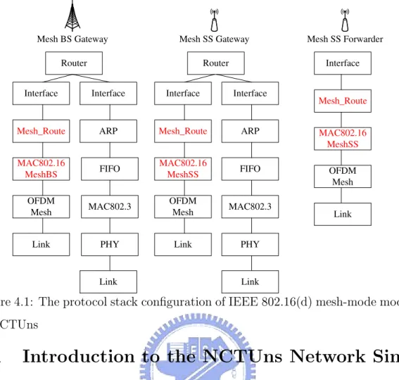
4.1 The protocol stack configuration of IEEE 802.16(d) mesh-mode mod-ules in NCTUns . . . 26
4.2 The format of a network-coded packet . . . 27
4.3 Two encoding rules . . . 33
4.4 The sending flow chart . . . 37
4.5 The receiving flow chart . . . 38
5.1 The extended hidden terminal problem in chain networks . . . 41
5.2 The extended hidden terminal problem in butterfly networks . . . 42
5.3 The format of the modified MSH-DSCH message . . . 44
5.4 The format of the modified Grant IE message . . . 44
5.5 The four-way handshake procedure . . . 45
6.1 The two simple topologies . . . 52
6.2 The 7-nodes chain topology . . . 52
6.3 The 9-nodes grid topology . . . 53
6.4 The 25-nodes grid topology . . . 53
6.5 The throughput of the Alice-and-Bob network . . . 54
6.6 The throughput of the butterfly network . . . 55
6.7 The throughput of butterfly network under different fresh clear timers 57 6.8 The throughput of 7-node chain network under different fresh clear timers . . . 58
6.9 The throughput of 9-node grid network under different fresh clear timers . . . 59
6.10 The throughput of 7-node chain network . . . 61
6.11 The throughput of 9-node grid network . . . 62
List of Tables
3.1 The mac management messages used in the mesh mode . . . 14 4.1 The notations used in our encoding rules . . . 30 6.1 Average end-to-end delay under different connection queue sizes in
Alice-and-Bob networks . . . 55 6.2 Average end-to-end delay under different connection queue sizes in
butterfly networks . . . 56 6.3 The average reduced ratio of collisions in the four-way handshake
procedure . . . 60 6.4 Average end-to-end delay under different connection queue sizes in
7-node chain networks . . . 64 6.5 Average end-to-end delay under different connection queue sizes in
9-node grid networks . . . 65 6.6 Average end-to-end delay under different connection queue sizes in
Chapter 1
Introduction
Network coding is a packet-encoding-decoding mechanism that aims to increase the data transmission efficiency of a network. It was first proposed by Ahlswede et al. [2] in 2000 and has gained much attention in recent years. A typical network coding mechanism is composed of two main operations: 1) mixing distinct outgoing packets on intermediate nodes; and 2) decoding mixed packets before (or when) they arrive at their destination nodes. With carefully finding and exploiting possible network coding opportunities, network coding can reduce the number of packet transmissions required for disseminating the same amount of data, as compared with traditional routing.
The development of network coding can be classified into two categories based on the network traffic patterns that it intends to address. One deals with the traffic generated by one or more multicast flows (referred to as intra-session coding) [4], while the other deals with the traffic generated by multiple unicast flows (referred to as inter-session coding). Several previous work has proven that the intra-session coding is beneficial for multicast-flow traffic and has well studied the characteristics of this network coding class. More information for the intra-session coding can be found in Chou et al ’s survey article in [3].
In contrast, developing an inter-session network coding scheme to effectively improve the performances of unicast flows is more challenging. In a unicast-flow
scenario, each flow has only one node as its intended receiver. In such a condition, blindly coding packets is likely to waste network bandwidth to disseminate a packet to nodes that are not interested in it. As such, designing an efficient inter-session network coding scheme is difficult because such a scheme needs to consider three problems at the same time: 1) routing path selection; 2) traffic load balancing; and 3) network coding decision. [15][6][9][13] [16] formulate the inter-session network cod-ing problem as a resource optimization problem that considers the aforementioned problems and use the linear programming technique to mathematically obtain the optimized solution to this problem.
Such theoretical studies have explored the characteristics of the inter-session coding problem; however, they do not propose feasible distributed protocols for scheduling inter-session network coding across a network. (Wang et al. [16] propose a theoretical distributed framework to control inter-session coding over a virtualized wireless network model. However, they do not present numerical results to evaluate the throughput and packet delay time performances of their proposed framework.) The reason is that a linear-programming-based scheduling approach usually requires high computation complexity to find the optimal scheduling, which means that a distributed algorithm developed based on this approach needs long time to converge1
(and may not converge under highly-changing traffic pattern).
In addition, these previous studies assume that no packet collisions occur in a net-work; that is, they do not consider the performance degradation of an inter-session network coding scheme caused by the well-known “hidden terminal problem.” The impacts of the hidden terminal problem can be discussed by two aspects. First, the packet collisions caused by the hidden terminal problem greatly reduce the over-hearing capability of each node, which is fundamental to the operation of network coding. As such, the performance of a network coding scheme will be degraded if hidden terminals are present.
Second, using virtual carrier-sensing mechanisms (e.g. the RTS-CTS mecha-1
The convergence of a network-coding protocol is defined as: the coding and routing decisions of all nodes in a network is consistent and loop-free.
nism used in the IEEE 802.11 network) and reservation-based mechanisms (e.g. the three-way handshake procedure used in the IEEE 802.16 mesh network) to prevent the hidden terminal problem from occurring is likely to introduce time and band-width overheads for packet transmission. Such extra overheads also decrease the performance benefits achieved by a network coding scheme. As such, considering the impacts of the hidden terminal problem is essential to designing a good network coding scheme that aims to run in real-life networks.
To the best of the authors’ knowledge, in the literature no inter-session network coding schemes that take the hidden terminal problem into account have been pro-posed. As such, the objective of this paper is to propose a practical inter-session network coding scheme that can be easily implemented in the real world and can improve the performance of a network. This paper has two contributions. First, in this paper we propose an easy-to-implement and easy-to-deploy inter-session net-work coding scheme that is based on the opportunistic approach. As compared with previous opportunistic coding schemes, such as COPE [12] and BFLY [14], our proposed scheme need not employ an additional protocol to find coding opportuni-ties or coding structures. Instead, our proposed scheme exploits only routing and MAC-layer information to find coding opportunities and coding structures. Using this advantage, it is easier to be realized in a real-life network, as compared with the previously-proposed opportunistic coding schemes.
Second, in this paper we point out a new “extended hidden terminal problem,” (denoted as the EHT problem) which can frequently occur in a wireless network using network coding. (In this paper, we call such a network a “network-coded wireless network.”) The EHT problem can result in the failure of network-coded packet decoding, thus significantly decreasing the performance of a network-coded wireless network. In Chapter 5, we will explain why the EHT problem cannot be solved by the currently-existing wireless network standards, such as the IEEE 802.11(b) and the IEEE 802.16(d) specifications. In addition, we also propose a bandwidth reservation mechanism that is extended from the IEEE 802.16(d) mesh-mode three-way handshake procedure to prevent the EHT problem from occurring.
Although our mechanism proposed in this paper is specific to the IEEE 802.16 mesh network, it can be used as an example protocol design to eliminate the EHT problem for other network-coded wireless networks.
The rest of this thesis is organized as follows. In Chapter 2, we present related work and explain the different of our work and other previous work that oppor-tunistically performs network coding. In Chapter 3, the background of the network coding theory and the IEEE 802.16(d) mesh network are introduced. In Chapter 4, we propose our opportunistic inter-session network coding scheme and explain the detail issues of practical implementation. In addition, we explain the EHT problem and provide our solutions in Chapter 5. Furthermore, we present the simulation results and performance evaluations in Chapter 6. Finally, we propose possible extensions to our work in Chapter 7 and conclude the thesis in Chapter 8.
Chapter 2
Related Work
In the literature, several papers ([15][6][9][13][16]) have theoretically studied the inter-session network coding problem. In these studies, the authors modelled the inter-session network coding problem as a resource allocation problem that considers a number of factors, such as coding chances, queue size of nodes, and link capacity, and then find the optimal allocation for such a problem using linear programming-based approaches. Although these previous studies have discussed the characteris-tics of the inter-session network coding problem, turning their mathematical results into feasible distributed real-life protocols is difficult due to the huge computation complexity required by the linear-programming-based mathematical operations.
On the other hand, another track of inter-session network coding research is opportunistic coding, which aims to develop sub-optimal yet easy-to-implement and easy-to-deploy network coding schemes for unicast-flow wireless networks. In [12], Katti et al. implemented the COPE coding scheme over a real-life IEEE 802.11(b) wireless network. COPE performs network coding operation in an opportunistic manner, and its main operations are described below.
Using COPE, each node periodically broadcasts a ”reception report” message to its neighboring nodes. A reception report message of node i contains the informa-tion of packets that node i currently possesses. Based on received recepinforma-tion report messages, a network node maintains a packet information pool that records which
packets are currently possessed by its neighboring nodes. Each time when a node is going to transmit a data packet, it first looks up the packet information pool to check whether a coding opportunity exists or not. If so, this node mixes several packets that can be coded together to form a new network-coded packet and sends this network-coded packet out. If not, it defers the transmission of this packet until the maximum allowed waiting time has elapsed. In this condition, the packet should be transmitted immediately.
COPE uses the simple protocol explained above to help a node find coding opportunities within its one-hop neighborhood, i.e., using COPE a node is only capable of finding coding opportunities in chain-based or start-based topologies. In [14], Omiwade et al. propose the BFLY scheme that allows nodes to find coding opportunities in a butterfly topology. The operation of BFLY is briefly described here.
Using BFLY, each node i should periodically broadcast a hello message to its neighboring nodes. A hello message of node i contains node i’s neighboring node list and a neighbor vector describing the relative neighboring relationship (regard-ing the butterfly structure) of node i and its neighbor(regard-ing nodes. As such, each node can maintain all of its possible butterfly coding structures based on the hello messages advertised by its neighboring nodes. Upon transmitting data packets, a node can check whether its outgoing packets can generate coding opportunities over the maintained butterfly structures. If so, the node mixes these packets to form a network-coded packets and then transmits the packet out.
The idea of BFLY is similar to our proposed network coding scheme, which can find coding opportunities in chain-based, star-based, and butterfly-based topologies. However, as compared with COPE and BFLY, our proposed network coding scheme has several advantages. First, COPE and BFLY need to employ additional proto-cols to exchange the information of either packets possessed by neighboring nodes (in COPE) or butterfly-structure relationship of neighboring nodes (in BFLY). In contrast, our proposed network coding scheme utilizes only routing and MAC-layer neighborhood information to find coding opportunities and thus need not employ
any additional protocols to operate. As such, the bandwidth and time overheads generated by such additional protocols can be eliminated. In addition, because the operation of our proposed coding scheme need not rely on additional protocols, the implementation complexity and deployment cost of our proposed scheme is greatly lower than that of COPE and BFLY.
Second, to the best of the authors’ knowledge, the coding schemes proposed in the previous studies, such as COPE and BFLY, do not consider the performance degradation caused by the hidden terminal problem. As such, these schemes can only work well over an interference-free wireless network, which is uncommon in the real world. In contrast, our work takes the hidden terminal problem into account and studies its impact on the performances of inter-session network coding.
Besides, we point out a new extended hidden terminal problem that only takes place in a wireless network-coded network. With the presence of hidden terminals and extended hidden terminals, the goodputs obtained by application programs in a wireless network-coded network can be greatly decreased (even much lower than those in a traditional routing-based network). To address this problem, our pro-posed network coding scheme employs an ”extended three-way handshake procedure (ETHP)” to eliminate the HT and EHT problems in a wireless network-coded net-work. Our simulation results show that our proposed network coding scheme can effectively eliminate the occurrence of HTs and EHTs and significantly increase the application goodputs of of a wireless network-coded network.
Chapter 3
Background
This chapter gives the background of this thesis which includes two main aspects: Network Coding and IEEE 802.16(d) networks. In the following, we shall briefly introduce the fundamental knowledge about each territory.
3.1
Overview of Network Coding
Network coding is a new paradigm to increase the utilization of both wired and wireless networks. The core idea of network coding is to allow information mixing in the intermediate nodes. A receiver sees these mixed-up packets and deduces from the messages which were originally intended for the data sink. The fundamental concept of network coding was first stated by [2], which demonstrated the famous butterfly example. Consider the topology in Fig. 3.1, where source node S1 wants to send packet P1 to destination T1, and source node S2 wants to deliver packet P2 to destination T2. Using the traditional techniques of packet forwarding, packet P1 and P2 should be passed through R1 and R2, and finally be delivered to the destination T1 and T2. As a convention, we use the term “routing” to describe this traditional solution. Unfortunately, there will be a bottleneck at link between R1 and R2 in the routing solution if each link capacity is only one packet.
In [2], the network coding scheme sloves this problem by mixing packets P1 and P2 at node R1. A simple network coding mixing method is using the “exclusive
Figure 3.1: The general butterfly example
or” (XOR) to encode two packets. In a butterfly topology like Fig. 3.1, at first time node S1 and S2 broadcast P1 and P2. Node R1 gets both two packets and node T1 and T2 also receive P2 and P1 respectively. Each broadcasting casts one transmission time. Also, node R1 and R2 broadcast the encoding packet “P1+P2”, and node T1 and T2 can decode to the packets they want. Therefore, we can reduce the transmissions from six to four and produce a coding gain of 64 = 1.5.
As mentioned in Chapter 1, most of the network coding researches after [2] focus on the theoretical studies rather than the pratical approaches. Since the theoretical studies have explored the characteristics of network coding, they do not propose a feasible protocol and some assumptions of them can not be ignored in real-world networks. On the contrary, the pratical implementations like [12][14] are based on the opportunistic approach. They need to find coding opportunities or coding structures to proceed the network coding scheme. The coding structures includes chain, star and butterfly structures. The butterfly structure is shown as in Fig. 3.1 and its coding benefits are explained above. In addition, the chain and star (or cross) structure are depicted in Fig. 3.2. At the chain structure example as Fig. 3.2 (a), node S1 and S2 want to deliver P1 and P2 to each other through node R1. The network coding opportunitie is obvious where node R1 encodes (P1,P2) and
Figure 3.2: The chain and star coding structures
broadcasts to each sinks. The Structure in Fig. 3.2 (a) can reduce the transmissions from four to three and generate a coding gain of 43 = 1.33 by using network coding. Similarly, the star structure shown as Fig. 3.2 (b) is a kind of variations of the chain structure. On the other hand, many chain structures comprised a star structure. Fig. 3.2 (b) is also named the cross structure which forms by two chain structures. In short, if there is only one forwarding node in the center (like R1) and N source nodes transmit data to each opposing side across the forwarding node, the central node can encode N packets and broadcast once. The coding gain of the star structures can be computed as 2N
N+1 if all destinations can decode successfully.
3.2
Overview of IEEE 802.16(d) Network
IEEE 802.16(d) standard (also known as WiMAX) [1] is a promising next-generation technology for the future FBWA1 systems. In this standard, the MAC layer is
structured to support multiple PHY-layer specifications, each suited to a particular operational environment. In addition, the standard also supports IP-based network
1
Physical layer (PHY-layer) Security Sublayer MAC Common Part
Sublayer (MAC CPS) Service-Specific Convergence Sublayer (CS) M AC -la y er
Figure 3.3: The IEEE 802.16(d) protocol layering architecture (i.e. all WiMAX nodes are layer-3 devices).
Two operating modes are defined in the standard: the PMP mode and the Mesh mode. Firstly, the PMP mode is designed to resolve the last-mile problem in traditional wired environment. When this mode operates in the 10-66 GHz li-censed bands, its line-of-sight (LOS) applications offer data rates grater than 120 Mbit/sec. Secondly, the Mesh mode is an extension mode to support the infras-tructure of Wireless-MANs. In addition, this mode operates in the licensed bands below 11 GHz and uses orthogonal frequency division multiplexing (OFDM) tech-nology. Therefore, it can support non-LOS (NLOS) applications. Compared with the traditional 802.11-based mesh network, the WiMAX Mesh Network is able to provide higher throughput and larger coverage. In this thesis, we will only focus on the Mesh operating mode.
Fig. 3.3 illustrates the reference mode defined in the standard. The MAC layer consists of three sublayers, which are the Service-Specific Convergence Sublayer (CS), the MAC Common Part Sublayer (MAC CPS) and the Security Sublayer. The PHY layer adopts single-carrier technology to support LOS applications, and uses OFDM technology to support NLOS applications.
The functionality of each MAC sublayer is presented in the following. In the Service-Specific Convergence Sublayer, the major function is classifying the data from upper layer, and then associating them to appropriate MAC connections. In the
MAC Common Part Sublayer, all of the main Mesh operations such as network entry process and network synchronization are specified. The Security Sublayer provides the subscribers with privacy across FBWA system by encrypting the connections between BS and SS. In this section, we regard the MAC CPS as MAC layer directly and only focus on this sublayer.
3.2.1
Definitions of Teminologies
In the following, some terminologies used extensively in the standard are introduced. • Mesh BS and Mesh SS
The station that has a direct link to backhaul services (i.e. the Internet) outside the WiMAX Mesh network is termed as a Mesh BS2. Other stations
are termed as Mesh SSs3.
• Sponsoring Node, Candidate Node and Registration Node
These three types of nodes are only used in network entry process. The Spon-soring Node assists a new node in entering the WiMAX Mesh network during the network entry process. The new node involved in this process is termed as a Candidate Node. The Mesh node which assigns Node IDs to the new nodes is termed as a Registration Node.
• Link
A link is a directional mapping between two MAC peers for either control messages exchange or traffic flows transmission. It is identified by an 8-bit link identifier (Link ID) and used to construct the connection identifier (CID). Note that a link is a logical communication between two Mesh nodes in their MAC-layer views. • Connection 2 Base Station 3 Subscriber Station
Generic MAC
Header Payload (optional) CRC (optional)
MSB LSB
Payloads
(CS packet or management message) Subheaders
(if necessary)
Figure 3.4: The mac PDU format
A connection, instead of a link, is a unidirectional mapping between two MAC peers. For a specified link, many different connections are constructed by either the various QoS parameters or the different network logical ID (i.e. A link can construct multiple connections). In addition, a connection is identified by a 16-bit connection identifier (CID). Note that a connection is a logical link between two Mesh nodes in their MAC-layer views as a link.
• Neighbor, Neighborhood and Extended Neighborhood
The station that a node has a direct link connecting with is defined as the node’s neighbor. Neighbors of a node form a neighborhood, and they are considered to be one-hop away from this node. An extended neighborhood covers not only a node’s neighbors but also the neighbors of those being in the node’s neighborhood.
MAC PDU
As shown in Fig. 3.4, the MAC PDU comprises a 6-byte generic MAC header, a variable-length Payload and an optional 4-byte cyclic redundancy check (CRC). In addition, there are zero or more subheaders and the payloads carried in the Payload field. The payloads, instead of the Payload, are used to carry either the data from upper layer (such as IP packet) or the MAC management messages.
The major functions of generic MAC header, subheader and CRC are described as follows. The generic MAC header indicates what the subheaders are carried in the Payload field and whether the CRC is appended. The extra information, such as the payload fragmentation state or the transmitting Node ID, are specified
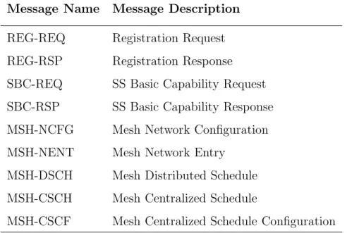
Table 3.1: The mac management messages used in the mesh mode
Message Name Message Description
REG-REQ Registration Request
REG-RSP Registration Response
SBC-REQ SS Basic Capability Request
SBC-RSP SS Basic Capability Response
MSH-NCFG Mesh Network Configuration
MSH-NENT Mesh Network Entry
MSH-DSCH Mesh Distributed Schedule
MSH-CSCH Mesh Centralized Schedule
MSH-CSCF Mesh Centralized Schedule Configuration
in the corresponding subheaders. The CRC covers the generic MAC header and the Payload to achieve error-protecting. Table 3.1 lists the important management messages used in the Mesh mode.
Frame Structure
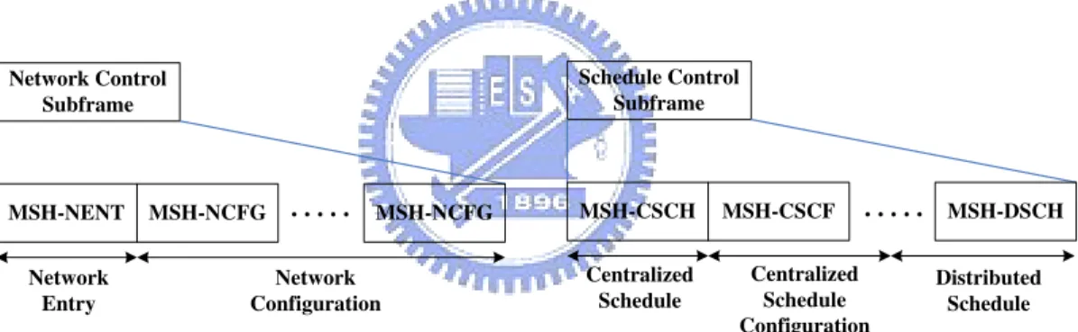
The Mesh frame structure is illustrated in Fig. 3.5 and Fig. 3.6. Only time division duplex (TDD) is supported in the Mesh mode. A Mesh frame consists of a control subframe and a data subframe. In addition, the control subframe is divided into transmission opportunities (TxOpps); the data subframe is divided into minislots. There are two kinds of control subframes which named the network control subframe and the schedule control subframe. The former is used for network configuration, new node entry and network synchronization. The latter is used to exchange the coordinated scheduling information. In the following, we shall introduce the control subframe and data subframe in detail.
The length of a control subframe is a fixed value of MSH-CTRL-LEN TxOpps. Each TxOpp comprises 7 OFDM symbols. A control subframe is either a network control subframe or a schedule control subframe. In the network control subframe,
Frame n-1 Frame n . . . . Frame n+k time
Control
subframe Data subframe Network Control
subframe Schedule Control
subframe or
Figure 3.5: The mesh frame structure
Network Control Subframe MSH-NCFG MSH-NENT MSH-NCFG Network Entry Network Configuration
1 opportunity (MSH-CTRL-LEN - 1) opportunities
(a) The network control subframe
Schedule Control Subframe MSH-CSCF MSH-CSCH MSH-DSCH Centralized Schedule Centralized Schedule Configuration (MSH-CTRL-LEN - MSH-DSCH-NUM) opportunities MSH-DSCH-NUM opportunities
(b) The schedule control subframe
Distributed Schedule Data Subframe Burst from SS#j Burst from SS#i Burst from SS#n
(c) The data subframe
Up to 256 minislots
. . .
. . . . . . . . . .
one TxOpp is reserved for the network entry process, and the (MSHCTRLLEN -1) TxOpps following the reserved one is used for the network configuration. On the other hand, in the schedule control subframe, MSH-DSCH-NUM defines the number of MSH-DSCH TxOpps per schedule control subframe. In addition, during this subframe, the first (MSH-CTRL-LEN - MSH-DSCH-NUM) TxOpps are reserved for centralized scheduling. The remainder is allocated for distributed scheduling. The parameters about the Mesh frame format are carried in the Network Descriptor of NCFG message.
The data subframe is divided into (up to) 256 minislots. In this subframe, the coordinated scheduling data and the uncoordinated scheduling packets will take place. A scheduled allocation consists of one or more minislots.
3.2.2
Network Entry Process
A new Mesh SS node shall perform the network entry process to join the Mesh network before starting a scheduled transmission. In the following, we elaborate this procedure step by step.
1. First of all, the new node listens to the ongoing transmissions in the air and searches for MSH-NCFG messages to synchronize coarsely with the Mesh net-work. In the meantime, the new node shall build a physical neighbor list according to the information carried in the MSH-NCFG message.
2. When enough information is acquired, the new node selects a Sponsor Node from its neighbor list, and it becomes a Candidate Node. Moreover, the new node shall synchronize its time to this Sponsor Node by the assumption of no propagation delays.
3. By exchanging MSH-NENT and MSH-NCFG messages, the Candidate node and the Sponsor node establish a temporary schedule named Sponsor Channel. 4. Through the Sponsor Channel, the Sponsor Node assists the Candidate node to finish the basic capabilities negotiation and authorization with the BS.
Sponsor Node REG-REQ Candidate Node Tunneled REG-REQ Tunnel REG-RSP Registration Node time REG-RSP Tunnel the message Assign a Node ID for the Candidate Node Extract the message Retrieve the Node ID from the message
Figure 3.7: The registration process
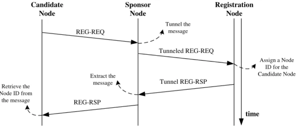
Afterward the Candidate node shall perform the Registration Process to obtain its Node ID, as shown in Fig. 3.7.
5. At the beginning of the Registration Process, the Candidate Node transmits a REG-REQ message to register with the Registration Node via its Sponsor Node. Upon receiving the REG-REQ message the Sponsor Node tunnels the message by prepending a tunnel subheader, a UDP header and an IP header. The tunneled message is sent to the Registration Node, which can optionally be co-located with the Mesh BS. Upon the reception of this message, the Registration Node assigns the Node ID of the Candidate Node and replies the tunneled REQ-RSP message. When receiving this tunneled message, the Sponsor Node shall extract the message and forward the REQ-RSP message to the Candidate Node. Eventually, the Candidate Node obtains its Node ID and accomplishes the Registration Process.
6. While finishing the Registration Process, the Candidate Node continues to acquire an IP address using DHCP and retrieves the current system time via the protocol defined in IETF RFC 868. Furthermore, it downloads the file containing operational parameters by using TFTP.
7. Finally, after completing above processes, the Candidate Node closes the Spon-sor Channel and becomes a functional node.
Node 2 MSH-NCFG: LinkEstIE:Challenge Node 1 MSH-NCFG: LinkEstIE:ChallengeResponse MSH-NCFG: LinkEstIE:Accept
Figure 3.8: The procedure of the link establishment process
3.2.3
Link Establishment Process
The Link Establishment Process is a three-way handshake procedure that performs a simple authentication and establishes two unidirectional links between a pair of neighboring functional nodes. Before the new node can transmit data packets, it has to establish links with its neighbors by a Link Establishment Process. In the following, we take an example to explain this procedure step by step and illustrate it in Fig. 3.8.
1. At first, the Node 1 begins the Link Establishment Process by sending a chal-lenge message to Node 2.
2. While receiving the challenge message, the Node 2 will try to authenticate Node 1. If the authentication is successful, the Node 2 will create a link from itself to Node 1 and then send back a response challenge message carrying this link value to Node 1.
3. Similarly, when receiving the response challenge message of Node 2, the Node 1 first performs the authentication for Node 2. If the authentication is successful, a link is established from itself to Node 2. Finally, the Node 1 will transmit an acceptance message carrying the link value to Node 2. This message also indicates that the Link Establish Process has been finished. Therefore, two one-way links are created safely between the Node 1 and Node 2.
3.2.4
Network Synchronization
In the WiMAX Mesh network, functional nodes periodically broadcast MSH-NCFG messages to exchange network configuration information with their neighbors. This procedure is named the Network Synchronization. Moreover, the transmission tim-ing of the synchronized messages is determined by a pseudo-random algorithm. The algorithm works without explicit negotiation and is completely distributed, fair and robust. In the following, we introduce the Network Synchronization and the pseudo-random algorithm respectively.
Network Synchronization
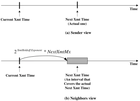
In the Network Synchronization, a node does not broadcast its exact next Xmt Time (i.e., the time slot when a node transmits its MSH-NCFG messages). In contrast, a node advertises an interval covering the actual Xmt Time. The interval is only composed of a 5-bit Next Xmt Mx and a 3-bit Xmt Holdoff Exponent for reducing the signaling overhead. Consequently, as shown in Fig. 3.9, the neighbors only know the interval that covers the actual next transmission time (Next Xmt Time) of the sender. The interval of the Next Xmt Time can be computed as follows:
2XmtHoldof f Exponent·N extXmtMx < N extXmtT ime ≤ 2XmtHoldof f Exponent·(NextXmtMx+1)
A node broadcasts not only its own Next Xmt Mx and Xmt Holdoff Expo-nent but also these two values of all its one-hop neighbors. Therefore, every regular node possesses the scheduling information within its extended neighborhood.
Pseudo-random algorithm
When a node is able to transmit the MSH-NCFG message, it shall schedule its next transmit time of MSH-NCFG message. The determination of the Next Xmt Time is accomplished by a pseudo-random algorithm according to the information deriving from its neighbors. In the following, we define the terminologies used in
Time Current Xmt Time
(b) Neighbors view
Next Xmt Time (An interval that Covers the actual Next Xmt Time) NextXmtMx Exponent XmtHoldoff * 2 Time Current Xmt Time
(a) Sender view
Next Xmt Time (Actual one)
Figure 3.9: The Next Xmt Time in both sender’s and neighbors’ views this algorithm.
• Xmt Holdoff Time
This is the number of MSH-NCFG TxOpps after Next Xmt Time. In this period, a node is not eligible to transmit any MSH-NCFG packet. This value can be computed as follows:
XmtHoldOf f T ime= 2XmtHoldof f Exponent+4
• Earliest Subsequent Xmt Time
The Earliest Subsequent Xmt Time indicates the earliest time when a node is capable of competing the candidate TxOpp, and it can be obtained by
EarliestSubsequentXmtT ime= 2XmtHoldof f Exponent·N extXmtMx+XmtHoldof f T ime+1
• Temp Xmt Time
Temp Xmt Time starts from the TxOpp which is equal to current Xmt Time plus Xmt Holdoff Time. This time is when this node can compete for TxOpps. If this node does not win the election, Temp Xmt Time will be set to next TxOpp until this node wins.
By definition, the node only competes for TxOpps later than the current Xmt Time plus the node’s Xmt Holdoff Time. That’s when the Temp Xmt Time starts from. Before the election begins, Mesh nodes shall determine what neighbors are eligible to compete for the Temp Xmt Time. There are three conditions in the following. If a neighbor meets one of them, the neighbor node is eligible.
1. The Next Xmt Time interval of the neighbor includes the Temp Xmt Time.
2. The Earliest Subsequent Xmt Time of the neighbor is less than or equal to the Temp Xmt Time.
3. The schedule of the neighbor is unknown.
When a Mesh election for the Temp Xmt Time is held among the sender and its eligible neighbors, a pseudo-random mixing number f(N ode ID, T emp Xmt T ime) is
com-puted for each of the nodes involved in the election. If f(Sender′s N ode ID, T emp Xmt T ime)
is the greatest among all numbers, the sender sets its Next Xmt Time equal to Temp Xmt Time, i.e. it can use the winning TxOpp to transmit its MSH-NCFG message. Otherwise, the Temp Xmt Time is advanced and the algorithm is re-peated until the node wins a TxOpp. Note that the fairness is ensured by the algorithm and the seeds (Temp Xmt Time) are different for every TxOpp.
After the Next Xmt Time is decided, it is converted into the corresponding Next Xmt Mx based on the specified Xmt Holdoff Time. Then the Next Xmt Mx and the specified Xmt Holdoff Time are added to the outgoing MSH-NCFG message.
3.2.5
Distributed Scheduling
In the WiMAX Mesh network, the network resources (i.e. minislots) may be al-located by three different scheduling modes: the centralized scheduling mode, the distributed scheduling mode and combination of above two modes. In this thesis, we only focus on the distributed scheduling.
In the distributed scheduling mode, schedules are established in a distributed way in which all the Mesh nodes involved are regards as peers (including the Mesh BS). The schedules are set up by a three-way handshake mechanism, which ensures the established schedules to be collision-free within the extended neighborhood. In the following we describe the distributed scheduling mode in more detail.
The distributed scheduling mode is divided into two operational modes, namely the coordinated mode and the uncoordinated mode. In both coordinated and un-coordinated modes, schedules are established between two nodes using a three-way handshake mechanism by the MSH-DSCH message exchange. In the coordinated distributed scheduling mode, the MSH-DSCH messages are transmitted over Tx-Opps in the schedule control subframe without collisions. In contrast, in the un-coordinated distributed scheduling mode, the MSH-DSCH messages can only be exchanged in the data subframe. Therefore, collisions may occur in the uncoordi-nated distributed scheduling mode. In this thesis, we only discuss the coordiuncoordi-nated distributed scheduling mode.
There are four kinds of information elements (IEs) that can be included in a MSH-DSCH message. The MSH-DSCH:SchedulingIE carries the coordinated dis-tributed scheduling information: Next Xmt Mx and Xmt Holdoff Exponent. The MSH-DSCH:RequestIE is used to convey resource requests on a specified link with the demand expressed in minislots. The MSH-DSCH:AvailabilityIE indicates free minislots ranges of the requesting node, which one MSH-DSCH:RequestIE can be corresponded to multiple MSH-DSCH:AvailabilityIEs. The granting node uses the MSH-DSCH:GrantIE to specify the range of granted minislots which selected from the free minislots reported by the requesting node. When it is sent by the requesting node, the DSCH:GrantIE acts as a grant confirmation called MSH-DSCH:ConfirmIE.
In the following, we explain the three-way handshake mechanism step by step, which is illustrated in Fig. 3.10. Note that each MSH-DSCH message transmission is just requiring one TxOpp. Therefore, it needs three time TxOpps to achieve the three-way handshake mechanism where two TxOpps are for the requesting node and
Effective transmission range
Requesting node
Granting node
1. The requesting node transmits a MSH-DSCH:RequestIE and one or more MSH-DSCH:AvailabilityIEs for requesting a schedule.
Requesting node
Granting node
2. The granting node responses a MSH-DSCH:GrantIE specifying the actual schedule.
Aware of the schedule Requesting node Granting node
3. The requesting node sends back a MSH-DSCH:ConfirmIE, containing a copy of the MSH-DSCH:GrantIE, to confirm the schedule.
Aware of the schedule Aware of the
schedule
one is for the granting node.
1. The requesting node first transmits a MSH-DSCH:RequestIE and one or more MSH-DSCH:AvailabilitiyIEs to ask for a schedule.
2. Upon reception of the requesting message, the granting node responds a MSH-DSCH:GrantIE specifying the actual schedule. In addition, the neighbors (ex-cept the requesting node) of the granting node shall assume that the schedule will take place as granted.
3. When receiving the granting message, the requesting node sends back a MSH-DSCH:ConfirmIE which is a copy of the MSH-DSCH:GrantIE to confirm the schedule to the granting node. Moreover, the third parties (i.e. the request-ing nodes neighbors except the grantrequest-ing node) shall keep silence durrequest-ing this schedule to avoid collisions.
Chapter 4
Design and Implementation
In this chapter, we explain the design and implementation of our proposed network coding scheme for IEEE 802.16(d) mesh networks. The design of our proposed net-work coding scheme includes the collaboration of the MAC layer and the employed routing protocol. In our design, the packet encoding-decoding functions and coding scheduler are implemented in the MAC layer. The coding scheduler needs the next-hop information of each outgoing packet to examine whether a coding opportunity exists. Such information can be easily acquired by consulting the collaborative rout-ing protocol, which is usually installed inside the operatrout-ing system. Although our proposed network coding scheme employs a cross-layer design, the cost to integrate functions in different layers is insignificant.
We evaluate our proposed network coding scheme using the NCTUns network simulator, which can use real-life Linux protocol stack and real-life application pro-grams to conduct simulation. In Section 4.1, we first introduce NCTUns and presents our implementations over this simulation platform. In Section 4.2, we explain the de-tailed formats of the network-coding packet header, which contains the information necessary to the operation of our proposed network coding scheme. We then explain the designs of the packet encoding-decoding mechanism and the coding scheduler in 4.3. Finally, in Section 4.4 we elaborate the control flow of a network coded packet from the sending node to a receiving node.
Figure 4.1: The protocol stack configuration of IEEE 802.16(d) mesh-mode modules in NCTUns
4.1
Introduction to the NCTUns Network
Simu-lation Platform
The NCTUns network simulator [17] is a high-fidelity and extensible network simula-tor. By using a novel kernel re-entering simulation methodology, the protocol stacks of real-life Linux operating systems can be used to conduct simulation. As com-pared with other existing network simulators, real-life UNIX application programs can directly run on top of NCTUns without any modifications. This unique feature makes the simulation results generated by NCTUns more accurate and realistic.
NCTUns supports lots of different network protocols, and all of them are imple-mented as protocol modules. In this these, we modify the implementation of the IEEE 802.16(d) mesh-mode protocol modules, which was first developed by Chu et al. [5] and refined by Hsu et al. [7][10][19]. The architecture of the IEEE 802.16(d) mesh-mode modules is illustrated in Fig. 4.1. As shown in this figure, an IEEE 802.16(d) mesh network is composed of four modules: Mesh Route, MAC802.16 MeshBS, MAC802.16 MeshSS, and OFDM Mesh.
Figure 4.2: The format of a network-coded packet
The Mesh Route module determines the routes of each packet and maintains a routing table for a network node. It also implements the application programming interfaces (APIs) of the route inquiry function, which is needed by the MAC-layer coding scheduler.
On the other hand, the MAC802.16 MeshBS and MAC802.16 MeshSS modules implements the MAC-layer functions defined by the IEEE 802.16(d) mesh-mode standard. We implement the main packet coding-decoding functions in these two modules. Finally, the OFDM Mesh module implements the characteristics of OFDM channels and simulates the broadcasting nature of a wireless network.
4.2
The Format of a Network-coded Packet under
Our Proposed Scheme
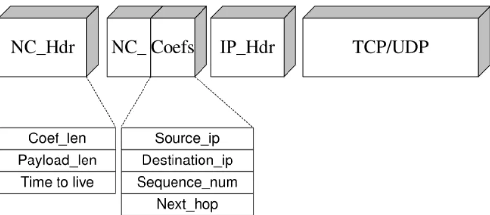
Our proposed network coding scheme needs to add an additional network-coding header into each outgoing packet such that intermediate nodes can differentiate whether an incoming packet is network-coded or not. Such network-coding header is inserted in front of each packet’s IEEE 802.16 MAC header. The detail format of a network-coded packet is depicted in Fig. 4.2. The network-coding header can be divide into two parts: 1) the Network Coding Header (NC hdr) and 2) the Network Coding Coefficient (NC Coef). Following the network-coding header are the IP header and TCP/UDP layer-4 packet. The network-coding header is also called a shim header between the IEEE 802.16(d) MAC header and the general IP header.
In the following, we describe the fields of a network-coding header in detail. Network Coding Header
1. Coefficient Length:
This field indicates the number of Network Coding Coefficients. For a network-coded packet, this field is set to two because, our proposed network coding scheme only mixes packets belonging to two different flows. On the contrary, this field is set to one if the packet is fresh.
2. Payload Length:
For a network-coded packet, its data payload corresponds to a complete IP packet. When two fresh packets of different lengths are encoded together to form a new coded packet, the payload length field of the new network-coded packet should be set to the length of the longer fresh packet.
3. Time-to-live:
The Time-to-live (TTL) field shows the number of hops that a packet is allowed to be forwarded. In the next section, we will present our proposed network-encoding rules for finding coding opportunities in different coding structures. Usually, this field is set to one for all packets to avoid bandwidth wastage due to unlimited packet flooding. However, in a butterfly coding structure this field should be set to two for the operation of our proposed network coding scheme.
Network Coding Coefficient
A mixing packet may comprise two fresh packets. For each fresh packet, its Network Coding Coefficient part is composed of the following information.
1. Source IP Address:
coding scheme, Source IP Address and Sequence Number are regarded as the unique packet ID.
2. Destination IP Address:
This field indicates the IP address of the traffic destination node. We use this information for looking up the routing path.
3. Sequence Number:
For every traffic source node, the Mesh Route module will assign a sequence number for each local transmitting packet. As the description above, the unique packet ID is referred to Source IP Address and Sequence Number. 4. Next Hop:
In the network coding scheme, every node needs to overhear packets which are not for itself. For the sake of this reason, we use this information to notice the real next hop. We fill in this field by the routing information basically but sometimes modify it to perform the butterfly rule.
Adding the coding header into a packet generates a few bandwidth overheads. The Network Coding Header is of 12 bytes in length and the Network Coding Coef-ficient is of 16 bytes in length (for a fresh packet) or 32 bytes in length (for a mixing packet). As such, if we have a 1400-byte UDP packet, the overhead only accounts for 1.9% to 2.9%. Such a bandwidth overhead is negligible, as compared with the performance gain obtained from network coding.
4.3
Packet Encoding and Decoding
Under our proposed network coding scheme, at most two different fresh packets are exclusive-or-coded (XOR-coded) to form a network-coded packet. The reason why we use this simple coding design is explained here. According to [13], Wang at al. stated that the packet forwarding efficiency of coding two distinct packets is not
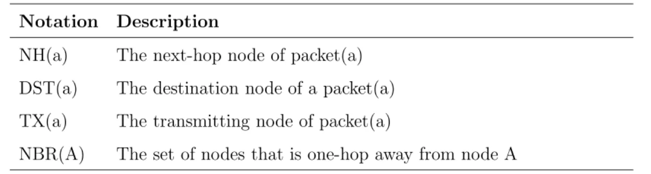
Table 4.1: The notations used in our encoding rules Notation Description
NH(a) The next-hop node of packet(a)
DST(a) The destination node of a packet(a)
TX(a) The transmitting node of packet(a)
NBR(A) The set of nodes that is one-hop away from node A
different from that of coding three and more distinct packets. In addition, regarding coding two distinct packets, the XOR operation can greatly reduce the computation complexity for network-coding a packet, as compared with other complicated coding operations (such as finite field operations), while, at the same time, achieve the same coding quality.
There are two advantages in our coding scheme. First, it is an easy-to-implemented and easy-to-deployed scheme. Our proposed scheme need not employ an additional protocol to find coding opportunities or coding structures. Second, as compared with COPE[12] and its extension, which only can support chain-based and star-based coding structures, our work can support chain-star-based, and butterfly-star-based coding structures at the same time. (Note that the star-based coding structure rarely happens in a real-life wireless network. As such, removing the star-based coding from our coding scheme results in insignificant performance impact.) As such, our proposed network coding scheme can find more coding opportunities that COPE-based schemes. In the following, we elaborate on the encoding mechanism employed by the proposed network coding scheme.
4.3.1
Main Encoding Rules
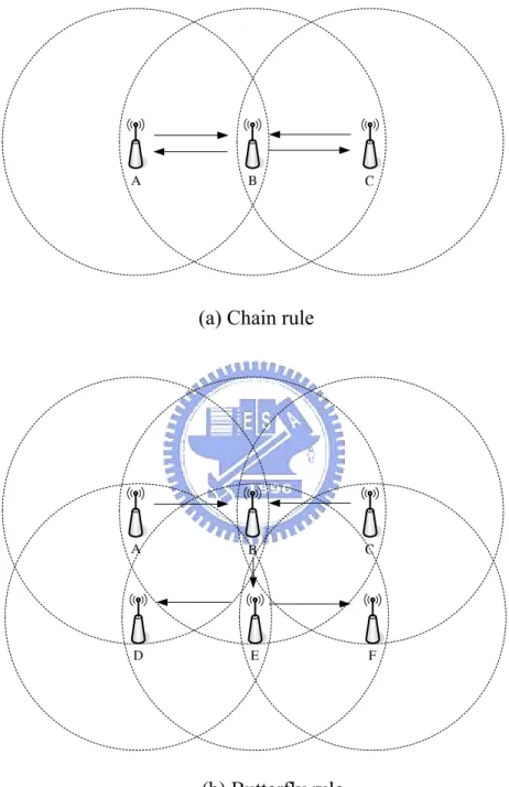
Chain Rule :
As shown in Fig. 4.3 (a), node B has received two packets from node A and C (denoted as Pkt(a) and Pkt(c), respectively). After receiving these two pack-ets, node B will check whether these two packets can form a coding opportunity
by checking whether the following rules are satisfied. 1. T X(a) = NH(c)
2. T X(c) = NH(a)
The chain rule is simple because only one-hop neighboring nodes (nodes A and C) of the coding node (node B) are involved. As such, the coding node can make sure that if these two conditions are satisfied, nodes A and C must possess Pkt(a) and Pkt(c), respectively. In addition, node A intends to receive Pkt(c) and node C intends to receive Pkt(a). As such, if node B transmits a network-coded packet (P kt(a) ⊕ P kt(c)), node A is able to obtain Pkt(c) by XOR-ing Pkt(a) and (P kt(a) ⊕ P kt(c)). On the other hand, node C is able to obtain Pkt(a) by XOR-ing Pkt(c) and (P kt(a) ⊕ P kt(c)). Using the chain rule, a node can reduce the number of packet transmissions from four to three and thus increase the packet transmission efficiency by 33%.
Butterfly Rule :
The chain-based network coding is easily implemented; however, such a cod-ing scheme can achieve at most 33% improvement of transmission efficiency. In contrast, the butterfly network coding can reduce the number of required packet transmissions from six to four, which can improve the packet transmis-sion efficiency by 50%.
The encoding-decoding mechanisms for the chain coding structure much dif-fer from that for the butterfly coding structure. Using the chain coding, a network-coded packet is decoded on its next-hop node. However, using the butterfly coding, the network-coded packet is decoded on the nodes that are two-hop away from the transmitting node. The operation of our butterfly coding is composed of two parts: rule checking and routing designation. The detailed design is explained below.
We use the topology shown in Fig. 4.3(b) as an example, where the network is composed of six nodes. Node A intends to deliver Pkt(a) to node F and node
C intends to transmit Pkt(c) to node D. On receiving these two packets, node B should check whether they satisfy the following rules or not.
Butterfly Coding Rules 1. NH(a) = NH(c) 2. DST (a) 6= DST (c)
3. (NBR(A) ∩ NBR(E)) − B 6= ∅ 4. (NBR(C) ∩ NBR(E)) − B 6= ∅
For a pair of packets, satisfying the above four rules indicates that they can form a butterfly coding opportunity. The first rule indicates that the two packets have the same next-hop node while the second rule indicates that they belong to different flows and are destined to different destination nodes, respectively.
A pair of packets satisfying the first two rules means that the routes of these two packets have a chance to perform butterfly coding. Then, the third and fourth rules check whether these two packets have opportunities to be decoded correctly in a butterfly structure, in case they are XOR-ed to form a network-coded packet. This checking is accomplished by examining if 1) nodes A and E have any common one-hop neighboring nodes other than node B and 2) nodes C and E have any common one-hop neighboring nodes other than node B. Rules (3) and (4) being satisfied means that the remedy packets for (P kt(A) ⊕ P kt(C)) can reach node E’ neighboring nodes, when nodes A and C transmit their own packets (i.e.,Pkt(A) and Pkt(C)) out, which means that the decoding for the network-coded packet (P kt(A) ⊕ P kt(C)) can succeed on nodes D and F.
If Pkt(A) and Pkt(C) pass rules (1) to (4), node B will mix these two packets to form a network-coded packet (P kt(A) ⊕ P kt(C)). Then, to make sure that Pkt(A) and Pkt(C) can reach nodes D and F, respectively, node B should designate the routes of the two mixed packets for node E. This is done by
setting the next-hop node fields of the component packets in the network coding header of the network-coded packet (P kt(A) ⊕ P kt(C)). The route of Pkt(A) on node E should be set to node D and that of Pkt(C) on node E should be set to node F, respectively. In addition, node B should set the TTL field of this coded packet to 2, which indicates that node E is allowed to re-broadcast this coded packet once again.
Finally, node B can send the coded packet (P kt(A) ⊕ P kt(C)) out. Upon receiving this coded packet, node E first checks whether it can decode this packet. Since it does not possess the remedy packets for this coded packet, it cannot decode this packet. In such a condition, it first decreases the TTL value of this coded packet and then checks if the TTL value is still larger than zero If so, it should re-broadcast this coded packet again. If not, it should drop this packet immediately.
Using such a design, the packet (P kt(A) ⊕ P kt(C)) can be flooded to nodes D and E. Because these two node have remedy packets for (P kt(A) ⊕ P kt(C)), they are able to decode the packets that they intend to receive (Pkt(C) and Pkt(A) in our example).
Our proposed scheme is feasible and easy to be implemented because, for a node, the one-hop neighboring node set of its neighboring node can easily obtained from the hello message or link state message received by the collab-orative routing protocol. In addition, for an IEEE 802.16(d) mesh network, such neighborhood information can be directly obtained from control-plane messages, such as MSH-NCFG messages or MSH-DSCH messages.
Route Designation for Next-hop Node 1. NH(a) ∈ ((NBR(C) ∩ NBR(E)) − B) 2. NH(c) ∈ ((NBR(A) ∩ NBR(E)) − B)
4.3.2
Decoding Rules
The packet decoding mechanism of our proposed scheme is simple and explained below. Every 802.16(d) mesh-mode node must maintain a fresh packet queue to store the packets that are sent by itself or overheard from its neighbor nodes. Upon receiving an coded packet, the receiving node first looks up the fresh packet queue using the Packet ID as index (i.e, source IP address and sequence number). If one of the coded packet’s component exists in the fresh packet queue, the receiving node will XOR the coded packet that it receives and the fresh component packet found in the fresh packet queue to obtain the other fresh component packet.
To save the storage space, each node periodically checks the fresh packet queue and removes packets that are obsolete. An obsolete packet is defined as a packet that has been existed in the network for more than a pre-defined time interval.
4.4
Complete Control Flow Explanation
In this section, we present the control flow of our proposed network coding scheme, which is discussed from the sending side and receiving side. The sending-side flow chart is depicted in Fig. 4.4 and the receiving-side flow chart is depicted in Fig. 4.5.
4.4.1
Sending Side
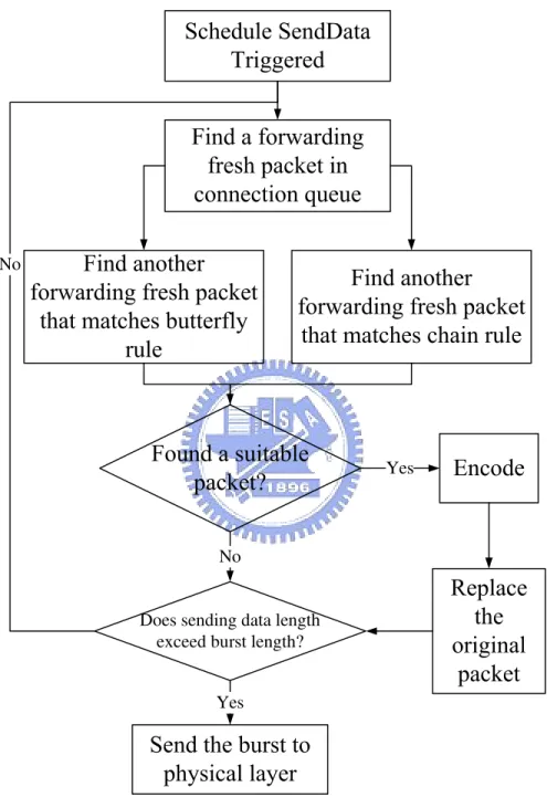
When the transmitting node sends or forwards a packet, the outgoing packet is first placed into one of the node’s MAC-layer connection queue. This action then triggers the MAC layer to perform a three-way handshake procedure to create a data schedule for the connection queue, if no data schedule corresponding to the connection queue exists so far.
As shown in Fig. 4.4, after the data schedule has been created, the MAC layer first scans the connection queue and tries to find whether packets that match the chain coding rules or butterfly coding rules exist. If such packets exist, the MAC layer then 1) codes these packets; 2) removes these packets out of the connection
queue; and 3) inserts the new coded packets into the connection queue. Such a scanning process is repeated until 1) the MAC layer cannot find any packets to perform network coding or 2) the total length of found packets have exceeded the length of a data burst that the MAC layer is currently allowed to transmit. After the encoding process, the MAC layer makes up a complete MAC-layer data burst for those coded packets and then transmit this data burst down to the physical layer to accomplish the sending process.
4.4.2
Receiving Side
The processing flow on the receiving side is shown in Fig. 4.5. On receiving a packet from the physical layer, the MAC layer first checks whether it is a fresh packet or not. For a coded packet, the MAC layer tries to decode it. If it cannot decode this coded packet, it then checks the TTL field and determines if it can re-broadcast it again. As aforementioned, if a packet is coded using the butterfly coding, its TTL field will be set to 2 initially. As such, if the TTL value of such a butterfly-coded packet is larger than zero, the MAC layer should insert this packet into the connection queue again to re-broadcast it.
However, in case a coded packet with TTL value being zero cannot be decoded correctly, the MAC layer should first place this packet into a coded packet queue. If the MAC layer can receive the remedy packet of this coded packet within a predefined time interval, the MAC layer can re-perform the decoding process for the coded packet. Otherwise, after the predefined time interval has elapsed, the coded packets that cannot be successfully decoded will be discarded.
On the other hand, if the MAC layer receives a fresh packet, it should first check if the packet is destined to itself or not. If it is, it should send this fresh packet to the upper layer. If not, it should store a copy of this packet in the fresh packet queue for future possible decoding. (This is because such a packet may be the remedy packet of future incoming network-coded packet.)
Chapter 5
Four-way Handshake Procedure
In this chapter, we discuss the impacts caused by the hidden terminal problem and the extended hidden terminal problem on a network coding scheme. Such an issue is rarely addressed in the previous studies, which greatly weakens the practicability of network coding over a real-life wireless network. To design a practical network coding scheme, in this chapter we explain the problems caused by hidden terminal nodes and extended hidden terminal nodes and propose a solution that is feasible in IEEE 802.16(d) mesh network.
The remainder of this chapter is organized as follows. We first discuss why the packet collision problem can affect the performance of a network coding scheme in Section 5.1. Then, we point out the extended hidden terminal problem that frequently occurs in a network-coded network and explain why it greatly degrades network coding performances in Section 5.2. In Section 5.3, we present our four-way handshake design to solve this problem in detail. Finally, we propose an algorithm to determine the activation time of a data schedule to further reduce the potential bandwidth wastage that may result from our proposed four-way handshake design in Section 5.4.
5.1
Packet Collision Problem in a Wireless
Network-coded Network
It has been known that, in a wireless network, the hidden terminal problem can result in frequent packet collisions. In a traditional IEEE 802.11 network, the RTS-CTS mechanism is used to prevent transmitted data packets from being collided. However, the RTS-CTS mechanism also greatly increases the bandwidth and time cost for a packet transmission. (Using the RTS-CTS mechanism, a data packet transmission should be accompanied by two control packet, i.e., the RTS and CTS packets.) As such, it significantly reduces the throughput performance of a wireless network.
In [12][8][11], Katti et al. have pointed out that the hidden terminal problem can degrade the performance of a network coding scheme due to the packet collisions that it causes. In addition, they also point out that using the RTS-CTS mechanism to solve the hidden terminal problem will diminish the performance gain achieved by network coding. Due to this reason, most of the previous network coding re-search assume that a wireless network is collision-free and no hidden terminals (and extended hidden terminals) are present. However, such an assumption is unrealistic for a real-life wireless network.
As explained in Section 3.2.5, the IEEE 802.16(d) mesh mode uses a reservation-based approach to schedule data transmission and employs a three-way handshake procedure to eliminate hidden terminals. Because a three-way handshake procedure can reserve a data schedule that spans at most 1.28 second, the bandwidth and time overheads for avoiding hidden terminals in 802.16(d) mesh networks can be amortized and less significant, as compared with those in 802.11 networks.
However, the three-way handshake procedure designed by the 802.16(d) mesh mode does not consider the extended hidden terminal problem that frequently occurs in a wireless network using network coding. The reasons why an extended hidden terminal problem occurs are explained here.
trans-Figure 5.1: The extended hidden terminal problem in chain networks
mission range of these two nodes, respectively. The solid arrow denotes the direction on which a node intends to its packets and the dotted arrow denotes the direction on which its neighboring nodes is likely to overhear this packet. Although the three-way handshake mechanism of the 802.16(d) standard can protect the transmitted packets from being collided on the intended receiver (nodes A and E in this example case), these packets are still collided on node C, which should overhear these packets to perform network coding.
In a traditional routing-based wireless network, such packet collisions are allowed and do not reduce the effective throughputs experienced by intended receiving nodes. Nevertheless, in a network-coded wireless network, if network coding is performed, coded packets may be collided on nodes that should overhear them for decoding network-coded packets. For example, in the example show in Fig. 5.1, node D should transmit a coded packet to both node A and node C to increase transmission efficiency. However, using the three-way handshake mechanism, this coded packet are protected only on node A. In contrast, it is collided with the one transmitted by node D on node C. As such, this packet cannot be correctly decoded on node C, which greatly degrades the performance gain achieved by network coding.
Such an extended hidden terminals can also appear in butterfly coding structures. As shown in Fig. 5.2, in a butterfly-based network-coded network, nodes D and F are very likely to lose the remedy packets required to decode network-coded packets broadcasted by node E, due to the collisions caused by extended hidden terminals. (In this case, the node pairs (A,E) and (C,I) are extended hidden terminals to
Figure 5.2: The extended hidden terminal problem in butterfly networks each, respectively.) Note that, because the original three-way handshake mechanism cannot solve this sort of hidden terminals. Hence, we call this sort of hidden terminal problems as the “extended hidden terminal problem.”
5.2
Modified Control Messages
To solve the “extended hidden terminal problem”, we enhance the original WiMAX three-way handshake scheduling procedure and name it to “four-way handshake” mechanism. Before describing the details of the “four-way handshake” mechanism, we shall explain the control message formats which we modified for the new schedul-ing procedure.
In Section 3.2.5, we express the original three-way handshake and the control message the nodes exchanged. Similarly, the four-way handshake mechanism uses the same MSH-DSCH control messages to notify the neighbors. However, we make a little modification of the message formats. As depicted in Fig. 5.3, we use the reserved field to achieve our goals. The two reserved bits of the MSH-DSCH message