國
立
交
通
大
學
資訊科學與工程研究所
碩
士
論
文
在疊蓋式網路利用網路編碼的安全與有效率的群播
方式
Network Coding for Secure and Efficient Multicast
in Overlay Network
研 究 生:吳經偉
指導教授:謝續平 教授
在疊蓋式網路利用網路編碼的安全與有效率的群播方式
Network Coding for Secure and Efficient Multicast in
Overlay Network
研 究 生:吳經偉 Student:Jingwei Wu
指導教授:謝續平 博士 Advisor:Dr. Shiuhpyng Shieh
國 立 交 通 大 學
資 訊 科 學 與 工 程 研 究 所
碩 士 論 文
A Thesis
Submitted to Institute of Computer Science and Engineering
College of Computer Science
National Chiao Tung University
in partial Fulfillment of the Requirements
for the Degree of
Master
in
Computer Science
September 2008
Hsinchu, Taiwan, Republic of China
中華民國九十七年九月
在疊蓋式網路利用網路編碼的安全與有效率的群播方式
研究生:吳經偉 指導教授:謝續平
國立交通大學 資訊科學與工程研究所
摘 要
近幾年來將群播服務放在疊蓋式網路中相關研究越來越受到重視,也有許多研究 顯示在疊蓋式網路是適合實現群播機制的環境。在現今的環境中,點對點的分享十分 的流行,熱門檔案被分散在許多節點中,而被特定的試用者所需求。所以在資料傳輸 中,我們可以發現中間幫忙傳遞的節點成了提昇整體系統效能中的瓶頸。網路編碼是 用來提高網路檔案傳輸的一種編碼方法。節點要有可以支援編碼和解碼檔案的功能。 在本篇論文中,我們在疊蓋式網路中,提出一個基於網路編碼的群播機制。並且我們 將提出的機制建立了一個數學模型,基於此數學模型,我們可以來比較系統的效能的 提升。由數學模型所顯示的結果證明藉由網路編碼,我們確實有提高原有群播服務的 效能。除此之外,我們也加上了雙向認證和團體金鑰的分配。我們不需要額外的封包 傳輸來達到上述的功能,相對的我們把上述的資料揹負在網路編碼的封包之中。Network Coding for Secure and Efficient Multicast in
Overlay Networks
Student: Jingwei Wu Advisor: Shiuhpyng Shieh
Department of Computer Science
National Chiao Tung University
Abstract
Many researches have shown that overlay network is an applicable environment for providing multicast service. In current Internet environment, popular data is shared and queried by many peers. The bottleneck may be the intermediate nodes that help forward packet from data providers to receivers and vice versa. Network coding is an information-theoretical coding method proposed to improve data transmission efficiency of a given network topology. It claims that nodes in the topology support to encode/decode data and with network coding, the efficiency of whole system can be improved. In this paper, we propose a network coding based multicast scheme in overlay networks. We model our scheme and shows that our work has better performance of system throughput and we also provide a mutual authentication and group key distribution scheme without other message transmission.
誌
謝
首先感謝指導教授謝續平教授兩年來幫助,讓我在交通大學這兩年半來獲得續許
多不少的經驗。從AsiaCCS Conference 到 TWISC 和 iCAST,再到 UC Berkeley,這兩
年來在各方面的經驗都成長不少。感謝老師給予我機會能有這樣難得的經驗。另外, 感謝實驗室的同學們,在我研究的過程中給予許多寶貴的幫助,給我指引方向,指正 我思慮上的漏洞。感謝碩一的學弟妹們,多虧了你們的幫忙,讓我們能專心準備論文 口試。 感謝所有對於本研究提供幫助與給予意見指教的朋友們。祝福所有人,事事順心 如意!
Table of Contents
1. INTRODUCTION...1
1.1 Data Request in Overlay Networks ...5
1.2 Multicast in Overlay Networks ...6
2. RELATED WORK...8
2.1 Multicast in Overlay Networks ...8
2.2 Network Coding based Multicast ...10
2.3 Network Coding based Multicast in Overlay Networks... 11
3. OBSERVATION...14
3.1 Bottleneck of Intermediate Node...14
3.2 Many-to-many Multicast ...14
4. PROPOSED MODEL...16
4.1 Notation ...16
4.2 Multicast Routing Path Formation ...18
4.3 Data Provider Communication ...19
4.4 Data Transmission ...20
5. PERFORMANCE EVALUATION...23
5.1 Overlay Network Modeling...23
5.2 Evaluation of System Throughput...27
6. CONCLUSION...29
List of Figures
FIGURE 1.1:NETWORK LAYER MULTICAST VS.OVERLAY NETWORK MULTICAST...1
FIGURE 1.2:CENTRALIZED ARCHITECTURE...2
FIGURE 1.3:DECENTRALIZED AND UNSTRUCTURED ARCHITECTURE...3
FIGURE 1.4:DECENTRALIZED AND STRUCTURED ARCHITECTURE...4
FIGURE 1.5:(A)RING-BASED MULTICAST AND (B)TREE-BASED MULTICAST...4
FIGURE 4.1:OVERLAY MULTICAST TOPOLOGY...16
FIGURE 4.2:MULTICAST ROUTING PATH FORMATION:REQUEST...18
FIGURE 4.3:MULTICAST ROUTING PATH FORMATION:RESPONSE...19
FIGURE 4.4:MULTICAST ROUTING PATH FORMATION:ACKNOWLEDGEMENT...19
FIGURE 4.5:DATA PROVIDER COMMUNICATION...20
FIGURE 4.6:DATA TRANSMISSION:DATA ROUTING IN TRANSMISSION PATH...21
FIGURE 4.7:DATA TRANSMISSION:DATA ROUTING IN GROUP...22
FIGURE 5.1:FIVE STATES MODELING...24
List of Tables
TABLE 4.1:NOTATION...17
1. Introduction
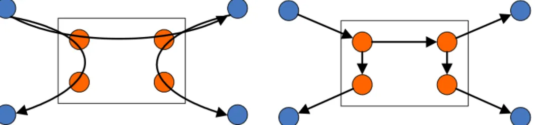
Multicast has been examined as an effective way to distribute data to potentially large group of peers. It is useful for scaling multi-party applications. However, deployment multicast service in network layer [1] has not widely adopted by most commercial Internet service providers (ISP), and thus theoretical researches related to multicast service have been over a decade or even more, large parts of the Internet are still incapable of native multicast support so far. Currently some researches have transfer their focus on implementing multicast services in the application layer [2][3][4][5]. This kinds multicast are called application layer multicast (ALM). They do not change the network infrastructure; instead they implement multicast forwarding functionality exclusively at end-hosts. Overlay network, also can be called application layer peer-to-peer network in this scope, is a computer network built upon the application layer and is thought as a platform to realize multicast service.
Figure 1.1: Network Layer Multicast vs. Overlay Network Multicast shows the different between network layer multicast and overly network multicast. The blue nodes are peers and orange nodes are routers. In network layer multicast, routers help duplicate and forward packets to other peers; but in overlay networks, peers help duplicate and forward packets to other peers.
Decentralized but structured, and Decentralized and unstructured architecture.
1) Centralized architecture: As Figure 1.2: Centralized Architecture shows that routing discovery between two arbitrary nodes is supported by centralized server. The centralized server maintains all routing information of nodes in the network. Nodes send routing discovery request to centralized server to receive destination’s position. The weakness of Centralized architecture is the network population issue. Because centralized server maintains all routing discovery information, the heavy holding leads the network size cannot be too large. Also the centralized server suffers single point of failure problem. If the centralized server shutdowns or is attacked, nodes cannot communicate each others; if the centralized server is compromised, Man-in-the-middle attack is possible occurred in routing discovery request of nodes. This kind of architecture suffers efficiency and security problems.
Figure 1.2: Centralized Architecture
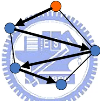
2) Decentralized and unstructured architecture: Because the problem of
centralized architecture, some researches have transferred to focused on decentralized system. It means that there is no centralized server in the system, each node need to record its neighbors’ information. When one node wants to communication other node, it uses flooding or random walks to separate routing discovery request. Other node who receives the request message helps forward to
destination. Figure 1.3: Decentralized and Unstructured Architecture shows that source node random selects one node to send request; and the selected one helps forward message to destination. Because nodes are randomly chosen, it may not be the optimistic paths. Without centralized server, there is no single point of failure problem in this kind of architecture. But because of the routing discovery request is using flooding or random walks, the system cannot guarantee requests will be received by destinations in limited TTL (Time to Live) value and unlimited TTL value may consume the network resource. So this kind of architecture also is unable to support large nodes in the network. KaZaA, BitTorrent and Overnet/eDonkey2000 are these kinds of overlay networks.
Figure 1.3: Decentralized and Unstructured Architecture
3) Decentralized and structured architecture: Based on the problems of
above two architectures, current researches is focusing on structured architectures, which means routing discovery is transmitted by some routing rules, but not based on flooding or random walk anymore. These kinds of systems have no centralized server to handle routing discovery requests, and nodes form the hierarchy for helping forward request messages. Each node also records its neighbors’ information. When node sends a routing discovery request, it follows the routing rule each system maintains. The routing rule is based on the hierarchy the nodes form. There are many kinds of hierarchies, such as ring based hierarchy, like Chord [7], tree based
hierarchy, like Pastry [9] and Tapestry [10], and others, like CAN [8]. Based on specific hierarchy, each system can guarantee that the routing discovery request is received by destination node in given maximum bounds of routing hops. Also many researches have shown that decentralized and structured overlay networks provide better performance on data routing than two above architectures [11].
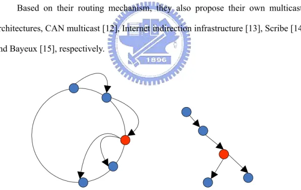
Figure 1.4: Decentralized and Structured Architecture
Based on their routing mechanism, they also propose their own multicast architectures, CAN multicast [12], Internet indirection infrastructure [13], Scribe [14] and Bayeux [15], respectively.
Figure 1.5: (a) Ring-based Multicast and (b) Tree-based Multicast
Since in overlay networks, popular files are shared with many peers and
queried by many others as well, intermediate nodes in routing paths may be the
bottleneck of data transmission.
loading if intermediate nodes and to improve the system throughput. Network coding is a method proposed to improve the efficiency of a given network topology. In conventional networks, each node either relays or replicates data from input links to output links. But in networks with network coding, each node supports to decode data from input links and to encode data into output links. With network coding, data provider needs to know topology of nodes in multicast paths. We add the topology search information into the data request and acknowledgement packets. We also propose a group key distribution scheme that group key piggybacks in topology search packets without additional packet for distributing it.
1.1 Data Request in Overlay Networks
First we introduce how data request in decentralized and structured overlay networks. The system assumes entries are roughly evenly distributed in both node and data namespaces. It means that each peer can request data with the identity of the data, sometimes the name of the data. Next we show the basic procedure of data request in overlay networks.
Any data provider holding data D computes H by using hash function (H=
hash(D)). Then the data provider informs the node whose identity is equal to or
similar to H. This node is called session node. The session node connects the relationship between the data provider and data D. Now any peer who wants data D computes H first from hash function and then generates a routing discovery request. It sends the routing discovery request to the session node. The session node forwards the request message to the data provider. After data provider receives the request message, it knows who wants the data and it can directly sends D to the peer.
size of the system and the base of the identity are defined as N and b separately, routing request can be achieved in at most logb(N) hops. The basic idea of routing request of some decentralized and structured overlay network architectures are very familiar. Data location can be easily implemented on overlay network architectures by associating a hash value H with each data D, and storing the (H, D) pair at the node to which the hash value H maps. Here we just give an abstract and the detailed can be found in each system. Based on data request routing, architecture also has its multicast protocol. Next we describe the basic idea how multicast can be realize in overlay networks.
1.2 Multicast in Overlay Networks
First, each peer who wants to query the data D computes H = hash(D). Second, the peer sends the request to the session node. The session node would receive many requests. Peers who have send requests form a group for this session time. Then the session node forwards all the requests to the data provider. The data provider would know all the peers requesting the data. It chooses some peers out of the group as intermediate node and sends data D to them. Intermediate nodes help to duplicate and forward data to other peers in the group.
In this paper we observe some phenomenon of the multicast service in decentralized and structured overlay network: the intermediate nodes may be the bottleneck of the system through multicast service. We study to use the information-theoretic technology called network coding to release the heavy loading of the intermediate nodes. Network coding is a coding method proposed to improve the data transmission efficiency of a given network topology. We will have more detailed description about network coding in section two. By solving the bottleneck
problem, we show that the overall system throughput is also enhanced.
The remainder of this paper is organized as follows. Section two is related work; section three is observation; section four is our proposed scheme; section five is performance evaluation, and section six is the conclusion.
2. Related Work
Decentralized and structured overlay network assigns node and data unique identifiers through hash function, separately. It maps node and data to the same namespace and then constructs corresponding relationship between node and data according to some distance metric, so an efficient lookup can be carried through.
Chord and Tapestry are two famous decentralized and structured overlay network architectures. Chord is a ring based architecture overlay network. Nodes form a ring in the order of their identities and each one maintains its neighbors’ identities to achieve data transmission. Chord claims that it can lookup any identity in namespace N at most log2N links. Tapestry is a mesh based architecture overlay network. Nodes form a tree for each data transmission with source as root. Tapestry claims that it can lookup any identity in namespace N with identity base b at most
logbN hop counts.
2.1 Multicast in Overlay Networks
Here we describe two famous multicast protocols in overlay networks: Internet indirection infrastructure (i3) and Bayeux.
Internet indirection infrastructure (i3) is based on Chord, which is distributed lookup protocol in application layer overlay network. Chord provides support for identity based routing discovery protocol. Peers form a virtual ring in application view for the routing. Each peer can map a given key to a specific data or node. Based on the routing protocol of Chord, Internet Indirection Infrastructure offers a rendezvous-based communication abstraction to support the peer-to-peer communication abstraction. It provides services like multicast, anycast, and mobility
upon application layer. Instead of explicitly sending a data to a peer, each data is associated with an identity; this identity is then used by the receiver to obtain delivery of the data. Peers who request data from the data provider to nodes with identical rendezvous, also called intermediate nodes, form a group. Since the data provider only needs to send data once to the intermediate node which helps forward data to each node in the group, it saves the data transmission overhead.
Above Internet indirection infrastructure is based on ring-based overlay architecture, Next Bayeux is based on tree-based overlay architecture.
Bayeux is an application level multicast architecture based on Tapestry. Tapestry is an overlay location and routing infrastructure that provides location-independent routing of messages directly to the closest data using only peer-to-peer links and without centralized resources. The routing within this infrastructure is purely soft state and easily repaired. Tapestry is self-administering, fault-tolerant, and resilient under load. Bayeux is application layer multicast that scales arbitrarily large receiver groups with fault tolerance. It also includes specific mechanisms for load-balancing across replicate intermediate nodes and more efficient bandwidth consumption. On top of Tapestry, Bayeux provides a simple protocol that organizes the multicast receivers into a distribution tree rooted at the data provider. Nodes with identical postfix of identity form a group with tree hierarchy. Because of the same postfix of identity, they can route to each other with fewer links. Data provider only needs to send data to the intermediate node which is the root of the sub-tree cover the group, and nodes forward data to their children in the sub-tree. The simulation results indicate that Bayeux maintains these properties while keeping transmission overhead low.
2.2 Network Coding based Multicast
The first one study focused on network coding is called Network information flow. It is propose by Ahlswede et al.With network coding, nodes have the capacity of encoding and decoding data at the per-message level using efficient codes methods. The aim of network coding is to use bandwidth more efficiently and thereby increase network capacity.
Consider a Overlay peer-to-peer network on which a number of data providers are to be multicast to certain sets of receivers. Network coding can be regarded as the Max-flow Min-cut Theorem for network information flow. It reveals that it is in general not optimal to regard the information to be multicast as a “fluid” which can simply be routed or replicated. Rather, by employing coding at the nodes, bandwidth can in general be saved.
In 2003, based on network information flow, linear network coding [16] proposes a method called linear-code multicast (LCM) for multicast service. Linear-code multicast encodes the packets into output links with using linear combination and decodes packets from input links by solving the system of linear equations. It shows that LCM achieves the max flow of data transmission theoretically from data provider to each receiving node.
Consider an application layer overlay network in which certain data provider multicast information to other peers on the network in the multihop fashion where every peer can duplicate and pass on any of its received data to others. Linear network coding is interested in how fast each peer can receive the complete information, or equivalently, what the information rate arriving at each node is. Allowing a node to encode its received data before passing it on, the question involves optimization of the multicast mechanisms at the nodes.Among the simplest
coding schemes is linear coding, which regards a block of data as a vector over a certain base field and allows a node to apply a linear transformation to a vector before passing it on. They formulate this multicast problem and prove that linear coding suffices to achieve the optimum, which is the max-flow from the source to each receiving node.
Since linear network coding using linear combination to combine many packets into one, all linear equations must be linear independent for sufficient to solve the linear equation system. Each node that helps encode packets may have some cooperation to build the liner equations. That means the node needs know the topology of overlay network. Random linear network coding [17] proposed in 2006. Random linear network coding uses random coefficients for packet encoding and shows that receivers who do not know the whole topology information have high probability to decode packets. Random linear network coding approaches for transmission and compression of information in general multi-source multicast networks.Network nodes independently and randomly select linear mappings from inputs onto output links over some field. They show that random network coding achieves capacity with probability exponentially approaching one with the code length. Benefits of this approach are decentralized operation and robustness to network changes or link failures.
2.3 Network Coding based Multicast in Overlay Networks
Microsoft in 2006 proposed a network coding mechanism in decentralized and unstructured peer-to-peer system [18]. They implemented a decentralized and unstructured content distribution system that uses network coding technology.Based on a prototype implementation of our system and the result of several live
distributions, they show that network coding is practical to improve the utilization of system resource in application-layer overlay environment with relatively small overhead, such as CPU processing and I/O activity.
Because their system is implemented in unstructured architecture, their application-layer routing discovery mechanism is based on flooding or random walk, which cannot support too many nodes in the network, as we mentions above. In our observation, network coding is better used in decentralized and structured overlay environment with handling multicast routing paths more easily.
Another research is studied by Zhu at el. [19]. They show that network coding is not suitable for current IP-based network; even in application-layer overlay networks, there exist many topologies where network coding fails to be more effective with respect to improving throughput. They construct multiple data paths from source to multicast group members and apply the concept of network coding in application-layer multicasts, motivating the case for application-layer coded multicast. They provide a distributed algorithm to construct a two-redundant multicast graph as the multicast topology with apply network coding applied. The result shows the throughput of end-to-end multicast is increased.
Their work seeks to improve end-to-end throughput in application layer multicast. They design the algorithm such that the costs of link stress and stretch are explicitly considered as constraints and minimized. Provable analytical and experimental results show that the introduction of two-redundant multicast graph and network coding may indeed bring significant benefits, essentially doubling the end-to-end throughput in most cases.
The work study by Zhu at el. has one problem is that its work does not show to be suitable for any of current overlay network architecture. Since multicast is only one of the benefits current famous overlay network architectures provide, it is hard
to bring a new system for just support multicast service.
In our work we try to propose a multicast mechanism with network coding on overlay networks, the overlay network platform we choose is Tapestry. Next we first show our observation of current works about multicast in application layer. Our work is based in these two observations.
3. Observation
There are two factors we observe in current overlay network architectures. The first is in order to improve the system throughput; we have to find the bottleneck of multicast service in overlay network architecture. The second is that multicast in overlay network usually has multiple data providers since the data is popular and owned by many peers.
3.1 Bottleneck of Intermediate Node
To enhance the system throughput, first we have to find the bottleneck on data transmission. It is easy to recognize that in multicast service, intermediate nodes help duplicate and forward data to all peers in the group. Data is buffered in intermediate nodes’ output queue until transmits to all receivers. On the other words, each time an intermediate receive n packets, it has to forward to m peers where m is the population size of the group. The delay is O(nm). To resolve this problem, we try to release the loading to other nodes in the system. The over all loading is not decreased but the average loading of each peer does.
3.2 Many-to-many Multicast
In realistic environment, we can observe that the wanted data usually is popular possessed by many peers. It means that there are usually more than one data providers in the system. With content request to different data providers, it may have more than one multicast paths to peers in a group. In establish of the steps of multicast in overlay network, the session node may forward requests to different providers from time to time for some purpose, such as load balance. Then different
providers may assign different intermediate nodes on the data transmission paths. With network coding abstract, each intermediate node encodes multiple packets into one new packet. The new packet received from intermediate nodes form a system of linear equations. Each peer can solve the system of linear equations when receive enough packets from intermediate nodes.
In this paper we try to improve the overall system throughput with network coding. We also propose a simple authentication scheme without additional data transmission. That means we piggyback our authentication information into the multicast establish procedure for preventing other loading.
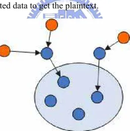
4. Proposed Model
Figure 4.1: Overlay Multicast Topology shows the topology of the multicast architecture. The orange node is data provider; the blue node inside the circle is peers in the group, and others are intermediate nodes. We utilize random network coding and propose an efficient multicast scheme in overlay networks. In our scheme, data may be separated into many packets; provider encrypts packets and sends to the network, some intermediate nodes take charge of data encode function; they use linear combination to encode many packets into one. After peers receive the new packets encoded from intermediate node, they re-transmit them to others. Each one can solve the system of linear equations when receiving enough packets and then decrypts the encrypted data to get the plaintext.
Figure 4.1: Overlay Multicast Topology
4.1 Notation
The notation is showed in Table 4.1: Notation. In our scheme, there are multiple data providers, and there is one primary data provider. It takes the charge of the multicast service of the group. All topology establishment and authentication are maintained by the primary data provider. On security part, PSK(x) is the pre-shared key of peer x with data provider. KG means the group key.
DP Data provider
PDP Primary data provider
P Peer
IN Intermediate node
PSK(x) Pre-shared key between peer x and data provider
RI Routing information
Request(x) Request of data x
ID(x) Identity of x
Nonce(x) Nonce of x
KG Group key
C = [c1, c2, … ] Vector of random number coefficients
Table 4.1: Notation
The scheme can be separated into three parts: The first one is multicast routing path formation; the second one is data provider communications and the third one is data transmission.
The purpose of the first part, multicast routing formation, is to form the network topology and to distribute group key. Peers in the group forward the routing information from data provider to itself to primary data provider. This part involves first three data transmission: Request, Response and Acknowledgement. Besides routing path establishment, we also use these three data transmission to achieve mutual authentication and key distribution. At the second part, the primary data provider collects all routing information from peers in the group. It then decides the multicast routing paths based on the routing information. Based on the algorithm, it chooses intermediate nodes which are the intersection of each path to receivers. The
in a specific time slot, each intermediate node encodes data receiving from data providers with linear combination and forward to peers in the group. Peer receives data and retransmits the data to other peers at least L times where L is the number of routing paths from intermediate nodes to the group. Then each peer can decode data by solving the system of linear equations. Next we describe the each procedure step by step.
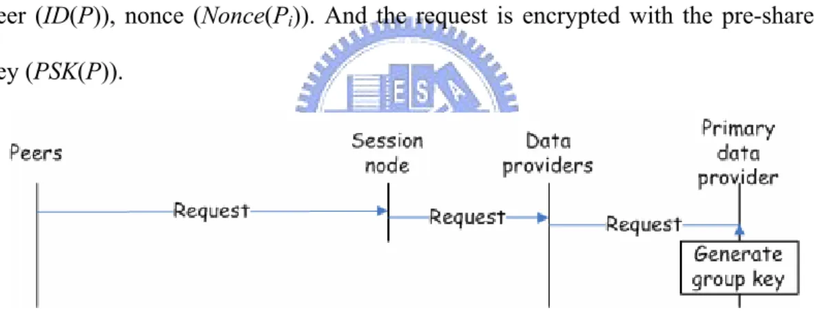
4.2 Multicast Routing Path Formation
At the first step, the peer who wants to join the group sends a request to the data provider. The request is composed of identity of data (ID(data)), identity of peer (ID(P)), nonce (Nonce(Pi)). And the request is encrypted with the pre-shared key (PSK(P)).
Figure 4.2: Multicast Routing Path Formation: Request
)} ( | ) ( | ) ( { ) (P i i PK ID Data ID P Nonce P E REQUEST = i
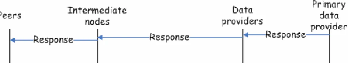
Since each peer may sends request to different data providers, they forward requests to primary data provider. The primary data provider sends the response back to data providers, and data providers forward to each peer. The response message is composed of identity of primary data provider (ID(PDP)), nonce of primary data provider (Nonce(PDP)), and nonce of peer + 1 (Nonce(Pi) + 1). Also the response message is encrypted with the pre-shared key (PSK(Pi)).
Figure 4.3: Multicast Routing Path Formation: Response
Each data provider received requests sends the response messages back to corresponding peers. } 1 ) ( | ) ( | ) ( { ) ( + =EPK P ID PDP Nonce PDP Nonce Pi RESPONSE i
Each intermediate node is the transmission paths add its routing information into the response message. The routing information means intermediate node’s identity and its input link capacity which can be measured roughly with propagation delay.
. _ |ROUTING INFO RESONSE RESPONSE = Capacity IN ID INFO ROUTING_ .= ( )|
Peer receives the response message and retrieves the group key. So far the group is not valid yet. Peer has to sends acknowledgement to data provider to prevent replay attack. The acknowledgement message is composed of routing information message and nonce of primary data provider + 1 (Nonce(PDP) + 1). Also the acknowledgement message is encrypted with the pre-shared key (PK(Pi)).
} 1 ) ( | { ) ( + =E RI Nonce PDP ACK PK Pi
Figure 4.4: Multicast Routing Path Formation: Acknowledgement
4.3 Data Provider Communication
intermediate node which is the intersection of routing paths is chosen to encode data with linear combination. The data providers with intersection intermediate node send different part of data since the data may be partitioned into many packets. Primary decides other data providers which packet of data to send to the group. With proper scheduling, each part of data could be evenly transmitted in the network.
Figure 4.5: Data Provider Communication
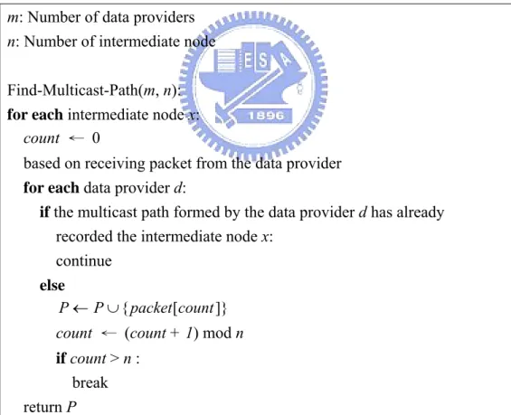
m: Number of data providers n: Number of intermediate node
Find-Multicast-Path(m, n):
for each intermediate node x:
count ← 0
based on receiving packet from the data provider
for each data provider d:
if the multicast path formed by the data provider d has already
recorded the intermediate node x:
continue else ]} [ {packet count P P← ∪
count ← (count + 1) mod n
if count > n :
break return P
Table 4.2: Algorithm of Data Provider Communication
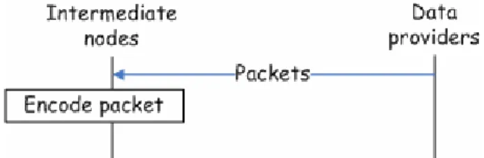
4.4 Data Transmission
path and data routing in group. Data routing in transmission path means data transmission from data provider to one peer of the group. Some intermediate nodes support encoding function. Data routing in group means the receiving peer sends the data to other peers in the group. Follow is the detailed description.
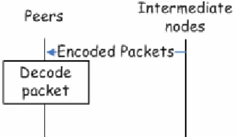
1) Data routing in transmission path: As we mentions above, data may be partitioned into many packets. Each data providers transmit specific packets indicated by primary data provider. They first encrypt the packets with group key and then send the packets to the peer who send request to it before. The intermediate node that is the intersection of paths not just helps forward packets but also supports to encode packets. The intermediate node sets up the timer when it receives the packet of data at once. If there are other packets coming before timeout, intermediate node starts the encode function. First, for each receiving packet, the intermediate node generates a random vector C. the size of the random vector is the same as the number of packets receiving from data providers.
] , , , [c1 c2 c3 K C =
The new encoded packet is generated with linear combination of packets and random coefficients. C PACKET PACKET c PACKET c PACKET PACKET new new new | 2 2 1 1 = + ⋅ + ⋅ = K
After generating the new packet, intermediate node continues to forward packet to peer in the group.
intermediate nodes. Peers in the group share the responsibility of intermediate nodes for forwarding packets. In our scheme, the number of time that intermediate nodes have to forward packets is number of routing path but not the number of peer in the group.
Figure 4.7: Data Transmission: Data routing in group
The number of pa ts transmitted in
e network. If the number of paths is n, each peer in the group must get at least n ths into the group is equal to the number of packe
th
different packets to solve the system of linear equations. When one retrieves packet from out side of the group, it re-transmits the packet to next n peers according the order if their identities. Because of n paths and n packet re-transmissions, without the situation of packet lost, each peer in the group can get enough packets to decode and to recover the encrypted data. After decrypting the data with the group key, all peers get the multicast data.
5. Performance Evaluation
In 2003, Ge et al. develop a mathematical model [20] to explore and illustrate fundamental performance issues of content sharing in overlay networks. The modeling framework is flexible enough to accommodate different characteristics of such systems. Simple models coupled with efficient solution methods can be used to understand and answer questions related to the performance of multicast in overlay network systems. In performance evaluation, we base on their work, propose a model for multicast service in overlay network.
5.1 Overlay Network Modeling
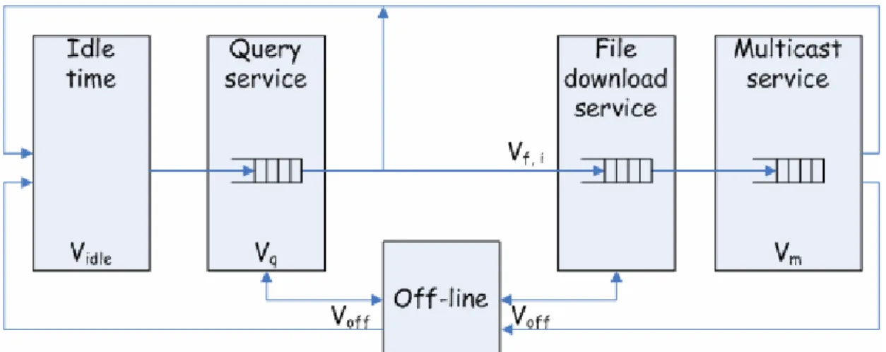
In 2003, Ge et al. propose a simple but accurate and extensible mathematical model for peer-to-peer file sharing system. Ge et al. model the overlay network system as a multiple class closed queuing network where each class consists of a fixed population of peers. In model Ge et al. study, each peer has four states to represent its behavior. These states are idle time state, query time state, off-line state, and file download service state. Because their work did not cover multicast service, we add a multicast service state to extend the modeling system. The behavior of multicast service is similar to query time state with a little change. We next consider these states in more detail.
Figure 5.1: Five States Model shows the model of the multicast service. Each block represents a state.
Figure 5.1: Five States Modeling
While on-line, a peer generates workload by posing queries to locate files; performing file downloads and helping multicast data forwarding.When a peer joins the system, moving from the off-line to the on-line state, it not only generates workload, but also brings service capacity to the system. In idle time state means that the node is idle, just online but doing nothing. Query service state means the node helps forward query to data provider. Off-line state means the peer shutdowns the service. File download service state means peer becomes data provider and handle the data downloading process. Multicast service state means peer help forward data to group.
We define the system throughput as the number of successful file downloads per unit time. The visit ratio of each state is presented as Voff, Vidle, Vq, Vf,i, and Vm.
Voff is equal to the probability of peer going off-line (Poff).
off
off
P
V
=
Vidle and Vq reflect the number of times on average a peer revisits the idle component and the query service queue, respectively. The parameter Na is the population of on-line peers and (Na) is the overall probability that query failure.
)
(
1
1
)
(
1
1
a q a idleN
q
V
N
q
V
−
=
−
=
Vf,i, is the frequency of visiting the file downloading service for i-th packet. The parameter pi is the probability that a request is associated with i-th most popular file and qf(Na, i) is probability that a query for the i-th most replicated file fails. Because decentralized and structured architecture guarantee that the routing request would be achieved in some given steps, here the probability of query failure is equal to zero.
0
)
,
(
)
(
1
))
,
(
1
(
,=
−
−
=
i
N
q
N
q
i
N
q
p
V
a f a a f i i fAnd Vm is the number of average times that a peer revisits multicast queue.
)
(
1
1
a mN
q
V
−
=
The service demand D is defined as the product of the respective visit ratio and the average service time. In this system, the utilization is proportional to its service demands. The corresponding demand of each state is presented as Doff, Didle, Dq, Df,i, and Dm. Doff is the demand of peer off-line. The parameter 1/λoff is the average time peer stays in off-line state.
off off off
P
D
λ
=
Didle is the demand of peer in idle state. The parameter 1/λidle is the average time peer stays in idle time state.
))
(
1
(
1
a idle idleN
q
D
−
=
λ
Dq is the demand of peer in query time state. The parameter µq(Na) is the service rate of peer helping send routing discovery request to data provider; Cq > 0 is determined by the capacity of a single peer to process a query; 0 < θ ≤ 1 is to balance the query workload distributed among peers on-line; and b is the number of neighbors whose identity is able to be the next forwarding peer of this routing discovery request.
θ
µ
µ
⋅
⋅
=
−
=
a a b q a q a a q qN
N
C
N
N
q
N
D
)
(
log
)
(
))
(
1
)(
(
1
Df,i is the demand of peer in file download service state. The parameter µf(Na,i) is the service rate for downloading the i-th most replicated file. It is composed of the population of on-line peers (Na); the basic service rate associated with the contribution of a single peer to the file service capacity (H); K and α are the scaling parameters of the zeta distribution which is the probability distribution used to model the data request behavior.
∑
=
⋅
⋅
=
−
−
=
= M j j a a f a a f a f i i fk
i
K
H
N
i
N
N
q
i
N
i
N
q
p
D
1 1 ,1
)
,
(
))
(
1
)(
,
(
))
,
(
1
(
α αµ
µ
Dm is the demand of peer in multicast service state. The parameter µm(Na) is the service rate of peer helping replicate and forward multicast data to receivers in the group; n is the number of peers in the group who request the data; and l is the
number of intermediate nodes helping encode data packets.
θ
µ
µ
⋅
⋅
⋅
⋅
+
⋅
=
−
=
l
n
n
C
N
C
N
N
N
q
N
D
b q a b q a a m a a m mlog
2
)
(
log
)
(
))
(
1
)(
(
1
5.2 Evaluation of System Throughput
Here the system throughput (T) is defined as the number of successful packets downloads per unit time. It has a upper bound that its inequality can be showed as:
m off M i f i q idle
D
D
D
D
D
N
T
+
+
∑
+
+
≤
=1 ,The parameter N is the total population of peers in the overlay network. By evaluating the system throughput, we can easily compare the performance improvement of multicast service with and without network coding technology.
We compare three multicast architectures, Bayeux, Internet indirection infrastructure, and our scheme. Internet indirection infrastructure (i3) is based on Chord. It provides multicast, anycast and mobility. Each node whose routing path from data provider to itself has identical intermediate node forms a group. Then data provider only needs to send data once to the intermediate node which helps forward data to each node in the group. Bayeux is an application level multicast architecture based on Tapestry. On top of Tapestry, Bayeux provides a simple protocol that organizes the multicast receivers into a distribution tree rooted at the data provider. Nodes with identical postfix of identity form a group with tree hierarchy. Because of the same postfix of identity, they can route to each other with fewer links. Data
sub-tree cover the group, and nodes forward data to their children in the subtree. Both Internet indirection infrastructure and Bayeux save the redundant transmissions from data to intermediate node.
0 50000 100000 150000 200000 250000 0 20000 40000 60000 80000 100000 120000
Population of online peer
Sy st em t hr oughput
T(NC) T(Bayeux) T(Internet indirection infrastructure)
Figure 5.2: System Throughput
Figure 5.2: System Throughput shows the system throughput. We can see that when population size increases, the system throughput of our scheme becomes much
6. Conclusion
With network coding, we provide a secure and efficient multicast protocol in overlay networks. First, in the view of performance, we eliminate bottleneck problem of intermediate nodes when doing multicast services. In order to reduce the unicast overhead of intermediate nodes, we separate the loading to the peers in the group. At the modeling analysis, it shows that the overall system throughput is actually improved. Second, we provide a simple but secure multicast protocol in overlay network. We also provide a mutual authentication and group key distribution scheme without other message transmission. It means that we piggyback the mutual authentication and group key distribution messages into the network coding messages. So there is no other overhead of message transmission to achieve the security.
7. References
[1] S. Deering and D. Cheriton. “Multicast Routing in Datagram Internetworks
and Extended LANs,” In ACM Transactions on Computer Systems, May 1990.
[2] Y.-H. Chu, S. G. Rao, and H. Zhang. “A Case for End System Multicast,” In
Proceedings of ACM SIGMETRICS, June 2000.
[3] J. Jannotti, D. Gifford, K. Johnson, M. Kaashoek, and J. O’Toole. “Overcast:
Reliable Multicasting with an Overlay Network,” In Proceedings of the 4th
Symposium on Operating Systems Design and Implementation, Oct. 2000.
[4] D. Pendarakis, S. Shi, D. Verma, and M. Waldvogel. “ALMI: An Application
Level Multicast Infrastructure,” In Proceedings of 3rd Usenix Symposium on
Internet Technologies & Systems, March 2001.
[5] S. Ratnasamy, M. Handley, R. Karp, and S. Shenker. “Application-level
multicast using content-addressable networks,” In Proceedings of 3rd
International Workshop on Networked Group Communication, Nov. 2001.
[6] R. Ahlswede, N. Cai, S.-Y. Li, and R. Yeung, “Network information flow,”
Information Theory, IEEE Transactions on, vol. 46, no. 4, pp. 1204–1216, Jul
2000.
[7] I. Stoica, R. Morris, D. Karger, M. F. Kaashoek, and H. Balakrishnan, “Chord:
A scalable peer-to-peer lookup service for internet applications,”
SIGCOMM Comput. Commun. Rev., vol. 31, no. 4, pp. 149–160, 2001.
[8] S. Ratnasamy, P. Francis, M. Handley, R. Karp, and S. Schenker, “A scalable
content-addressable network,” in SIGCOMM ’01: Proceedings of the 2001
conference on Applications, technologies, architectures, and protocols for computer communications. New York, NY, USA: ACM, 2001, pp. 161–172
location, and routing for large-scale peer-to-peer systems,” in
Middleware ’01: Proceedings of the IFIP/ACM International Conference on Distributed Systems Platforms Heidelberg. London, UK: Springer-Verlag, 2001,
pp. 329–350.
[10] B. Zhao, L. Huang, J. Stribling, S. Rhea, A. Joseph, and J. Kubiatowicz,
“Tapestry: a resilient global-scale overlay for service deployment,” Selected
Areas in Communications, IEEE Journal on, vol. 22, no. 1, pp. 41–53, Jan.
2004.
[11] Z. Ge, D. Figueiredo, S. Jaiswal, J. Kurose, and D. Towsley, “Modeling
peer-peer file sharing systems,” INFOCOM 2003. Twenty-Second Annual
Joint Conference of the IEEE Computer and Communications Societies. IEEE,
vol. 3, pp. 2188–2198 vol.3, March-3 April 2003.
[12] S. Ratnasamy, M. Handley, R. M. Karp, and S. Shenker, “Applicationlevel
multicast using content-addressable networks,” in NGC ’01: Proceedings of
the Third International COST264 Workshop on Networked Group Communication. London, UK: Springer-Verlag, 2001, pp. 14–29.
[13] I. Stoica, D. Adkins, S. Zhuang, S. Shenker, and S. Surana, “Internet
indirection infrastructure,” in SIGCOMM ’02: Proceedings of the 2002
conference on Applications, technologies, architectures, and protocols for computer communications. New York, NY, USA: ACM, 2002, pp. 73–86.
[14] M. Castro, P. Druschel, A.-M. Kermarrec, and A. Rowstron, “Scribe: a
large-scale and decentralized application-level multicast infrastructure,”
Selected Areas in Communications, IEEE Journal on, vol. 20, no. 8, pp.
1489–1499, Oct 2002.
dissemination,” in NOSSDAV ’01: Proceedings of the 11th international
workshop on Network and operating systems support for digital audio and video. New York, NY, USA: ACM, 2001, pp. 11–20.
[16] S.-Y. Li, R. Yeung, and N. Cai, “Linear network coding,” Information Theory,
IEEE Transactions on, vol. 49, no. 2, pp. 371–381, Feb 2003.
[17] T. Ho, M. Medard, R. Koetter, D. Karger, M. Effros, J. Shi, and B. Leong, “A
random linear network coding approach to multicast,” Information Theory,
IEEE Transactions on, vol. 52, no. 10, pp. 4413–4430, Oct. 2006.
[18] C. Gkantsidis, J. Miller, and P. Rodriguez, “Comprehensive view of a live
network coding p2p system,” in IMC ’06: Proceedings of the 6th ACM
SIGCOMM conference on Internet measurement. New York, NY, USA: ACM,
2006, pp. 177–188.
[19] Ying Zhu, Baochun Li, Member, IEEE, and Jiang Guo, “Multicast with
Network Coding in Application-Layer Overlay Networks,” IEEE Journal
on Selected Areas in Communications, vol. 22, no. 1, January 2004
[20] Z. Ge, D. Figueiredo, S. Jaiswal, J. Kurose, and D. Towsley, “Modeling
peer-peer file sharing systems,” INFOCOM 2003. Twenty-Second Annual
Joint Conference of the IEEE Computer and Communications Societies. IEEE,