2 MEDLIN, c w.: ‘A novel design technique for tuneable notch filters’.
Proc. Int. Symp. Circuits and Systems, New Orleans, Louisiana, USA, 1990, pp. 471-474
DUTTA ROY, S.C., JAIN, S.B., and KUMAR, R.: ‘Design of digital FIR notch filters’, IEE Proc.-Vis. h u g e Signul Process., 1994, 141, pp.
3 34--338
4 PE[, s.c., and TSENG, c.c.: ‘Elimination of AC intercfercnce in electrocardiogram using 1IR notch filter with transient suppression’, IEEE Tvuns. Biomed. Eng., 1995, 42, ( l l ) , pp. 1128- 1132
3
Overlapped patch elimination algorithm for
deformable mesh video coding
P
Yung-Ming
Chou and
Hsueh-Ming H a n gIndexing terms: Object detection, Motion estiniution, Video coding Updating mesh nodal points is onc of the major tasks in deformable mesh video coding. Owing to object movement and inexact motion estimation, nodal point tracking often results in
overlapped patches. A noniterative nodal point processing algorithm is proposed to solve this problem. Simulation results indicate that with this overlapped patch elimination algorithm,
the updated mesh can maintain a rathcr uniform distribution and
the moving object can be traced quite well.
Introduction: Video compression technology plays an important role in the transmission of video signals through channels with constrained capacity. Recently, deformable mesh coding has been explored [l - 31. Digital image warping is different from coiiven-
tional block-based schemes and is used to reduce the interframe correlation between two successive frames. Because of the mesh shape adjustment ability, it produces less noticeable blocking arte- facts in compensated pictures. More importantly, the object boundaries can be described in an efficient way to achieve object scalability.
There are two mapping directions for mesh warping, forward mapping and backward mapping. Forward mapping, together with object-based mesh adjustment, can provide an object tracking capability [l - 31. However, it is rather difficult to maintain the
mesh structure during the tracking process. Inaccurate motion estimation of nodal points may cause overlapped patches. To solve this problem, Wang and Lee [l] used an energy minimisation criterion. In their criterion, the deformation energy term is used to avoid mesh degeneration. However, their iterative procedure is quite complicated. In this Letter, we propose a noniterative nodal point processing algorithm used in conjunction with the conven- tional motion estimation algorithm i.e. block matching.
Proposed algorithm: In the development of our algorithm, we have adopted the coding structure in [2]. This structure includes two subsystems: a nodal tracking subsystem and a coding subsystem. In the tracking subsystem, the foreground object is separated from the background by conducting an image segmentation algorithm on the first frame. We then estimate the motion vector associated with each nodal point. A nodal point processing procedure is devised to adjust meshes so that illegal patches (defined below) are eliminated. The procedure involves three steps: (i) relocation of the ambiguous nodal points; (ii) merging the nearby nodal points and (iii) adjustment of the nodal points of illegal patches. The details are described below.
Inaccurate estimation is often the main reason which leads to degenerated patches, and usually occurs in the smooth regions of an image. Therefore, we interpolate the co-ordinates of the uodal
points located in the smooth region based on the nearest object boundary nodal points. Assume that
(x<,,
yJ is the co-ordinate of the nodal point in the smooth region, and (x,, yi), (xr, y“),(x,,
yJ, and (x,,, yh) are the nearest left, right, top, and bottom boundary nodal points updated by the motion estimation algorithm, respec- tively. Let n,, n,, n,, n,] denote the distances between these four points and (xc, yJ, respectively. The new nodal location is then the average bilinear interpolation of these four points. That isELECTRONICS LETTERS 19th June 1997
Vol.
33dt
+
db dbxt+
dtxb) (1) 1 d,21+
d l X ,1
&Yl+4Y,
(
4
+
d, xc=-( 2 dl+
d,+
d b y t dt+
+
db d t y b )+
yc = jThis interpolating process not only avoids inaccurate estimation in the smooth region, but also maintains a uniformly distributed mesh.
When an object is tracked for more than several frames, the neighbouring nodal points may either cluster together or depart from each other. Some patches are squeezed while the others are stretched. Patches may even overlap if no specific actions are taken. Therefore, we merge the nearby nodal points to eliminate degenerated or illegal patches. For each nodal point, we check its distance relative to the eight neighbouring nodal points. If any of them is less than a threshold (usually set to 3), the following merg- ing steps are performed to this pair of nodal points.
(i) If one nodal point is located on the image border, the other nodal point is merged to this nodal point.
(ii) If one nodal point is located on the edges, the other nodal point is merged to this nodal point to retain the edge informa- tion.
(iii) If this pair of nodal points is located horizontally, we measure the distance between the left nodal point and the nearest nodal point to its left, called the left distance. We also meas- ure the distance between the right nodal point and the nearest nodal point to its right, which is the right distance. If the left distance is greater than the right distance, then the right nodal point is merged to the left one, otherwise, the left nodal point is merged to the right one. A similar check and merge step is applied to the pair located vertically to maintain mesh uniformity.
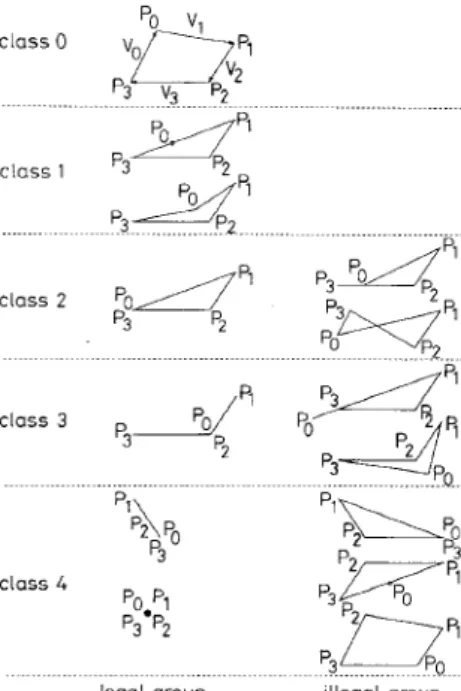
Even with the above nodal point adjustment steps, we still can- not guardntee that all the degenerated patches are eliminated. Thus, we further check the four vertexes of each patch based on the convex quadrilateral constraint [4]. If a quadrilateral patch is convex, all the vector cross products of the adjacent vectors (class 0 in Fig. 1) must be positive. That is
Vo
x
VI>
0 for the vertex Po VI x Va>
0 for the vertexPI
Va x V3
>
0 for the vertex PzVs x Vo
>
0 for the vertex F‘3In Fig. 1, all possible shapes of quadrilateral patches are displayed and classified into four classes. The class number is named after the number of rules being violated in eqn. 2. For coding purposes, we further divide these patches into two groups: legal and illegal. Illegal patches contain a negative area (i.e. an overlapped area). If an illegal patch is encountered, we merge a vertex that violates the constraint in eqn. 2 to a nearby vertex to force this patch to become legal in the same class. The location of the merged vertex is selected using the same rules described in the previous para- graph.
( 2 )
Simulation results: The ‘Suzie’ sequence is used to test the pro- posed algorithm. Its picture size is 352 pixels by 240 lines and 30 frame/s. The initial regular mesh is composed of 8 x 8 square patches. The exhaustive search block matching algorithm with half-pixel accuracy is used to estimate the motion vectors.
Table 1: Number of overlapped patches withlwithout nodal point processing
After step (i) After step (i) After step (iii)
I
Table 1 shows the number of overlapped patches (see Fig. 1) in some sampled frames. In general, the number of overlapped patches increases as the frame number increases. After using the merging steps of our method, this number is reduced dramatically. Finally, with convex quadrilateral checking, all the overlapped
patches are eliminated. Fig. 2 shows the mesh structure of the 30th frames using our procedure. After a number of frames, the mesh is still quitc uniform and the object is traced very well.
Po v
p3 v2 p7
c l a s s 0
"Ov;
legal group illegal group Fig. 1 All possilde quadrihteral patches
Fig. 2 Mesh structure in 30th frame o j 'Suzie' sequence
Conclusions: In this Letter, we have presented a nodal point processing algorithm in conjunction with the conventional motion estimation techniques for nodal point tracking in defonnable mesh coding. Using a simple procedure on the nodal points, all the overlapped patches can be eliminated. Because of the nodal dis- tance consideration in our merging steps, the processed mesh is quite uniform, which reduces the position errors resulting from motion estimation. Owing to its noniterative procedure and simpler arithmetic operations, this method needs a small amount of computational power.
0 IEE 1997
Electronics Letters Online No: 19970774
Yung-Ming Chou and Hsueh-Ming Hang (Depurtment of Electronics Engineering, National Chiuo TunK bniversity, Hsinchu, Taiwan 30050, Republic of Cliina)
E-mail: hmhang(@cc.nctu.edu.tw
28 April 1997
2 CHOU. Y . - M . , and H A N G , H -M : 'A video coding algorithm based on image warping and nonrectangular DCT coding'. Proc. SPIE Visual Commun. Image Process., San Jose, 1997, pp. 176-187 3 SEEK. P J.L , and TEKALP, A M . : 'Object-based video coding using
forward tracking 2-D mesh layers'. Proc. SPIE Visual Commun. Image Process., San Jose, 1997, pp. 699-710
4 SEFERDIS. H., and GHANBARI, M.: 'General approach to block matching motion estimation', Opt. Eng., 1993, 32, ( 7 ) , pp. 1 4 6 6
1474
1.5V
power supply CMOS voltage squarer
G.
Giustolisi,G.
Palmisanoand G.
PalumboIndexing terms: POWW S U ~ ~ ~ J J circuits, CMOS integrated circuits
A CMOS voltage squarer for low voltage applications is
proposed. The circuit works with a 1.5V power supply and provides a THD of <3'% with input signals up to 260mV,,,. A
0.3?4 lower THD is achieved with input signals up to 120mVp,.
Introduction: Low voltage operation has become a major design goal for most digital and aiialogue integrated circuits (ICs). This is because a low voltage power supply reduces the power consump- tion, which in turn means both an increase in the packing density, and an increase in the battery lifetime of portable equipment. Therefore, the design of analogue ICs with a low power supply is becoming mandatory, and great effort is currently devoted to the development of new solutions working with a l S V , or even lower voltage power supply [l - 41. Moreover, owing to scaling of
CMOS processes to submicrometre dimensions, low voltage non- linear CMOS circuits are gaining more attention by circuit design- ers who are involved in the realisation of R F front ends for cellular and cordless communications.
A useful nonlinear block is the voltage squarer [5 - 71. Indeed, it
can properly be arranged to implement various nonlinear circuits such as multipliers, balanced modulators, phase comparators, etc.
In this Letter a simple CMOS squarer is proposed which has a power supply of 1.5V and accepts input signals of up to 260mV,,.
M9 MI1
vB 2
_L vss Fig. 1 Schemutic diugrum of voltuge rquurer
Circuit description: The proposed squarer is shown in Fig. 1. Tran-
sistors MlLM4 perform the basic squarer function, M5-M7 set
the bias currents and M8-MI 1 form a low-voltage cascode current mirror, which provides the differential-to-single ended conversion.
The squarer function is obtained by properly taking advantage of the input-output characteristic of the MOS transistors in the saturation region. Indeed, considering transistors Ml-M4 to be in the saturation region and neglecting the channel-length modula- tion, the mobility degradation, and the body effect, we can state
References
I W A N G . Y , LFE, o., and VETRO, A : 'Use of two-dimensional deformable mesh structures for video coding, Parts I and 11', IEEE
Trans. Circuits Sys. Video Technol., 1996, 6, (12), pp. 636-659