國 立 交 通 大 學
資訊學院 資訊學程
碩 士 論 文
於光纖同軸混合型網路上自動救援纜線數據機出廠資料
之方法
An Auto-Recover Method for the Factory Data of Cable
Modem over the HFC Network
研 究 生:張屹銘
指導教授:袁賢銘 教授
於光纖同軸混合型網路上自動救援纜線數據機出廠資料之方法
An Auto-Recover Method for the Factory Data of Cable Modem over the HFC
Network
研 究 生:張屹銘 Student:Yi-Ming Chang
指導教授:袁賢銘 Advisor:Shyan-Ming Yuan
國 立 交 通 大 學
資訊學院 資訊學程
碩 士 論 文
A Thesis
Submitted to College of Computer Science
National Chiao Tung University
in Partial Fulfillment of the Requirements
for the Degree of
Master of Science
in
Computer Science
June 2010
Hsinchu, Taiwan, Republic of China
於光纖同軸混合型網路上自動救援纜線數據機出廠資料之方法
學生:張屹銘 指導教授:袁賢銘
國立交通大學資訊學院 資訊學程碩士班
摘要
隨 著 有 線 電 纜 資 料 服 務 介 面 規 範 ( DOCSIS, Data-Over-Cable Service Interface Specifications ) 產品的普及化,以及大量產品安裝到客戶端的情況下,如何保持產品的 品質以及快速修復有問題的量產產品,已經成為企業一個重要的課題。 在實務中某些情況之下,纜線數據機的出廠資料以及數位認證 (Digital Certificate) 等出廠資料會消失或損壞,根據傳統的手法,若是纜線數據機的這些有獨特性的出廠資料損 失因而造成校準表等各個數據機獨有的資料無法修復,就只有送回工廠一途,不只運送時間 過久要恢復這些資料也是十分的曠日費時。本論文的目的就是實現一種可以在線上提供資料 復原的方法,CAROL (Cable modem Auto-Recovery Online) 。 透過 Organic Computing 的精神,讓依照 DOCSIS 標準上線的產品,可以在我們的系統以 Network coding 為解碼編 碼方式所提供的服務下,順利的恢復重要的資料。我們的目標是能夠做到利用各個在線的裝 置所沒有用的到儲存空間,來互相保護重要的資料,因而能降低裝置回到產線來修復的比率。 關於實驗的部份,我們使用業界常用的測試方式,透過有有公信力的軟硬體設備,來驗 證復原資料的正確性,實驗結果是能完整地重新獲得原本該有的出廠資料。整體而言,經由 本論文所提供的方法與系統服務,只要能夠在纜線數據機內實現,並且透過在系統業者端針 對需求所下的設定,就能夠有效的提昇纜線數據機的可靠度。 II
An Auto-Recover Method for the Calibration Data of Cable Modem over the
HFC Network
Student
:Yi-Ming Chang
Advisor
:Shyan-Ming Yuan
Degree Program of Computer ScienceNational Chiao Tung University Abstract
With the popularization of the DOCSIS (Data-Over-Cable Service Interface Specifications) product, more and more devices are already installed in client side. The topic of how to maintain the quality and the speed of repairing becomes more and more important.
In some practical circumstances, the cable modem may loss the factory data which includes the calibration table and the digital certificates. These are unique and vital for the regular function of cable modem. In the traditional way of repairing this kind of product is shipping it back to the maintenance branch. We would like to present a solution to avoid time waste. It is named CAROL (Cable modem Auto-Recovery Online).
Within this thesis, we focus on applying the concept of Organic Computing and make good use of the advantages of Network Coding, then we could propose a really implementable method based on a common system over DOCSIS network to make the cable modem auto recover their unique calibration tables, digital certifications. Our goal is to make all of the process happen in client side, and simplified the multiple system operator's workload and it will be no necessity to conduct the routine maintenance in low-level system behavior. Thus we can reduce the probability of sending the cable modem back to factory. In our practice, we use the famous utility to measure the throughput of the CM which gets the recovered factory data, and it proved our method in the results.
Acknowledgment
關於這篇論文,最重要的是感謝袁賢銘老師這幾年來的指導,對於論文題目的尋找,老 師提供相當大的空間讓我自行思考,同時從旁輔助給我建議,讓我得以順利的訂出一個我喜 歡並且能夠發揮的論文題目,並且在論文遇到瓶頸時給我適當的提醒與教導,因而能好好完 成這份論文。另外還要感謝謝蘇俊銘博士的協助,針對這份論文初稿的表現和文字結構做出 了許多建議,並且肯花時間聽我對這份研究的看法,這實在是對這份論文在最後的收尾有很 大的幫助。還有也要感謝蕭兆鈞熬夜在百忙中,坐在我旁邊與我討論並訂正此論文中有關英 文文法與用字的錯誤。同時,謝謝和碩的同事陳信亦,在我設計系統時針對 DOCSIS 相關的 問題有許多不懂的地方幫我解惑。最後要感謝一直陪著我的家人以及多年的好友們,謝謝你 們的加油打氣,你們一定知道我有多感謝的。 IVTable of Contents
Acknowledgement
...
I V
Table of contents
...V
List of Figures
...VI
I
List of Tables...
VIII
1 Introduction...
1
1.1 Preface and Motivation ...1
1.2 Research Objectives...2 1.3 Research Contribution...3
2 Background
...6
2.1 Organic Computing...6 2.2 Network Coding...8 2.3 Factory data...9 2.3.1 Calibration table...9 2.3.2 Digital Certificates...112.3.3 The common arrangement for Recovery and Backup...1 3
3 System Architecture...1
6
3.1 Overview...1 6 3.2 T he Back-End Services ... 173.3 The Head End Devices...19
3.4 The End Nodes...20
4 Evaluations...
22
4.1 Nodes Implementation...22
4.1.1 Allocate the Jobs...22
4.1.2 Encoding and Decoding...26
4.2 Program Flow Scenarios...30
4.2.1 Node Scenarios...30
4.2.2 Program Flow...33
4.3 Scenario Demonstration...36
4.3.1 Overview...36
4.3.2 Implementing Services...40
5 Experiment and Results of Test...
...44
5.1 System Performance Test...44
5.2 Comparison...51
6 Future works and Conclusion...
54
6.1 Future works...54
6.2 Conclusion...54
7 Reference...56
List of Figures
Figure 2-1 The core schema of the Organic Computing... ...6
Figure 2-2 The standard example for The Network Coding... ...8
Figure 2-3 Illustrating a protocol stack for a cable modem ...10
Figure 2-4 Illustrating how a basic authentication works between the CM and the head end.... ...13
Figure 3-1 Overall System Architecture... ...16
Figure 3-2 An example for the CM configuration file ...18
Figure 3-3 TLV data in ASCII ...19
Figure 3-4 An example of the provision XML file ...21
Figure 4-1 Using XOR operation to merge different packets into one packet ...24
Figure 4-2 How to Generate blocks from the source data.. ...26
Figure 4-3 Illustrating an example for block generation of each byte... ....26
Figure 4-4 Exponentiation table and Log table using 0xde as the generator ...28
Figure 4-5 Using the look-up tables to do the multiplication method in the Galois field... ...29
Figure 4-6 Using the look-up tables to do the division method in the Galois field ...30
Figure 4-7 Illustrating a scenario for backup process ...31
Figure 4-8 Life cycle of a node ...32
Figure 4-9 Program flow chart ...35
Figure 4-10 Topology of the factory data distribution ...37
Figure 4-11 Off line scheme ...39
Figure 5-1 Test Topology of test 1 ...45
Figure 5-2 Protocols Configuration of IXIA slot 1 Port 1 ...46
Figure 5-3 Stream Control Configuration of IXIA slot 1 Port 1 ...47
Figure 5-4 IXIA IxRouter configuration ...47
Figure 5-5 Test Topology of test 2.... ...49
Figure 5-6 MRTG Daily Chart ...51
Figure 5-7 MRTG Weekly Chart ...52
List of Tables
Table 2-1 The traditional method for maintaining factory data... ...14
Table 4-1 A comparison of information delivery methods of DOCSIS products... ...23
Table 4-2 Task list ...43
Table 5-1 Comparison of Uni-Directional Downstream ...48
Table 5-2 Comparison of Uni-Directional Upstream ...48
Table 5-3 Comparison of UDP Downstream test ...50
Table 5-4 Comparison of UDP Upstream test ...50
Table 5-5 Comparison with CAROL system and Traditional method ...53
1 Introduction
1.1 Preface and Motivation
Even to present days, the competitive strength of the electronic industry has been to concentrate upon reducing the cost and more addictive features to software and the hardware performance enhancement. We always try our best to research and develop newly inventing fields to assure we can develop more powerful project to avoid error within product content. In the past, computer technology usually were used to improve hardware performance and made easy-to-use software. But, applying the great technology to reduce the cost is not a common strategy in business field.
More and more embedded products are equipped with computational power and a little free storage spaces. For such reason, they become more usable and flexible. When multifunction happens, it becomes unreliable in daily life. Since we already have computing power、free storage space device and it is essential for our daily life. We can make good use of these features to deal with some little issue which may consume excessive human resource but lower technique strength. As a result, we can use distributed computing as the main concept to reduce our maintenance cost.
On the other hand, the embedded systems become increasingly unstable and complex. We must handle it with extreme care. In our experience, normally if the cable modem encounter malfunction in client side and the problem can not be simply solved by manual reset. What we can do is just replace it with a new cable modem, or recall it to factory side and try to find out the problem after return to the manufacture facility. In some cases, one of these cases is power cycle suddenly, the cable modem just lost it's calibration table and digital certificates, so that malfunction occurs. What we need is to re-calibrate it or find a method to preserve it's calibration tables. In this general practice, we can not avoid the increasing cost of maintenance. Because each tuner has their different features. Even if we keep the general calibration data, it can not totally meet the requirement of
every tuner. And it is almost impossible to keep each identical calibration data for every cable modem. The digital certificates is a kind of the company property, it's not allowed to store in the client side. Based on the budgeting control, the multiple system operator (MSO) and the factory would not willing to preserve this kind of unique data. They have to create a huge data base 、equip complex hardware and assign human resource to maintain. It means they have to give those extra costs to assure the integrity of the calibration data. The whole process is contrary with the economic benefits. In our point of view, the cable modems have sufficient computing power、storage spaces and the ample band width to maintain the calibration data for each other. Since it is almost essential in our daily life, and cable modems bare be power off. We can restored the calibration data without the presence of every cable modems that hold part of backup data. This concept is similar to a kind of application of Network Coding. The other feature of DOCSIS (Data Over Cable Service Interface Specification) 3.0 is high transmission speed, there is 4 channels bounding for upstream can provide about one hundred Mbps. It can be conducted under the network computing. The whole process of factory data recovery or data distributing can be quickly completed.
1.2 Research Objectives
As we mentioned in the previous section, we try to make all the process could be resolved inside the cable modems, and make sure the cable modem can self-handling each necessary processes without or with the minimum management from the MSO. It is called the CAROL (Cable modem Auto-Recovery Online) system. In this thesis, we focus on applying the concept of Organic Computing and make good use of the advantages of Network Coding. However, a system could be named organic if all of its components and subsystems are well coordinated in a purposeful manner. Organic structures realize themselves as hierarchically nested processes, and structured to be able to meet upcoming challenges by goal-oriented reactions [1]. The Organic Computing is capable to achieve complex distributed systems with addictive abilities, such as configuration 、 self-organization 、 self-repair 、 self-optimization 、 self-protection [2] or adaptation. So that the
embedded systems become more life-like and can satisfy what we need. The embedded systems become free employees with no wadge. Therefore we believe the concept and principles of the Organic Computing are capable to satisfy our demands. Then we could propose a really implementable method which is based on a common system over DOCSIS network to make the cable modem auto recover their unique calibration tables, digital certifications and default settings. Our goal is to make all of the process happen in client side, and simplified the multiple system operator's workload. So that there will be no necessity to conduct the routine maintenance in low-level system behavior.
1.3 Research Contribution
This thesis will discuss how to make a automatic recovery method in the cable modem. This is a proposed and completed method which includes the provision method for the MSO, mechanism that distributes the factory data, action flows which can retrieve the original data, and how to add customized log for tracing the life cycle of each cable modem. Additionally, we proposed equations as the tips for the developer who can customize the original method into an more efficient method based on their specific and unique demand. And we also provide the test results which were testified by some common tools. Such authorized tools are commonly used in industry. We can easily compare the traditional method and our system by these test reports. There are four merits of this thesis can be summarized as the following parts:
•
The factory data is auto recovered and auto distributed
This is the most important part. We design some appropriate rules and patterns for internal behavior in the Hybrid Fiber-Cable network of the cable modems which should deliver some requested fairish functionality for protecting calibration data. To actually elevate the necessary degrees of freedom for adaptive behavior, we will definitely need the self-reconfigurable system for
this task. Choosing the recovery data distributing timing is the key of this system. In this thesis, we give a general introduction to this life-like method, and propose a generic calibration data exchanging architecture [3].
•
Flexibility and multiple methods of recovery
According to the actual usage of the cable modems over the Hybrid Fiber-Cable network, we design a flexible method to fit any possible case. The life-like system must be prepare an environment for the self-organization between cable modems, whether the amounts of CM is large or small. The method must be designed as which could be easily resumed original status after being stretched or expanded.
As for the recovery plan, we should consider not only automatic but also manual operation. The cable modems should be able to detect the changes in the surrounding environment, which in accordance with changes in the environment automatically set based on user's demand or behavior. If the user, for example, the MSO wants to performed restoration manually, we should provide theses selective options for users.
•
Less management
This system is a model of CM-CM interaction in which the calibration data processing has been thoroughly integrated into each objects and activities. In other words, this is an active protection system. Whether the activity is distribution or recovery, it should be achieved between the cable modems. This thesis provides a method to make all of the clients can cover each other without prejudice to common operations. After integration of all the cable modems into a group or many independent groups, this specific system becomes increasingly complex. This feature raises a new challenge for designing and implement .
•
Traceable logs
There should be some logs for history inquiry. As we mentioned before, this system must be flexible. We have to trace the process flow and make some notes, then we can handle any case that we might image or not. For example, if increasing number of cable modems join this system, we can study the operations and then evolve the system by the logs. To achieve this goal, we should apply the second research objective and try to design the log generator. The principle is to make the log generator simple and effective, and integrated into each important point in this system. Thus, it is important that input should be limited and simplified as much as possible. The application generates logs automatically, and the log is used only for research and recording. This demonstrate the need for new methods to evolve and control the behavior of this flexible systems and to create trustworthy systems which adapting to our needs.
2 Background
2.1 Organic Computing
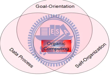
Figure 2-1 The core schema of the Organic Computing
As we illustrated in Figure 2-1, we demonstrate our most interesting field by drawing the core schema of the Organic Computing. The Organic Computing is a paradigm for the design a complex system. It was proposed by a department in University of Hanover that is SRA (System – und RechnerArchitekur)[9] . It mainly involved in the launch of the Organic Computing Initiative. [8]Also, the Organic Computing is a new vision for distributing embedded systems. In fact, when we try to design a method that really can help us to protect the factory data, the Organic Computing
is the first idea that attracts our attention. In the beginning, there is only a concept in our imagination. The whole concept is to make the embedded system can take care of each other, and the concept of the Organic Computing seems to be helpful in building our system.
The extended applications and ideas from the Organic Computing are already been published many times. It is similar to the Ubiquitous Computing. The initial incarnation of ubiquitous computing was in the form of "tabs", "pads", and "boards" which was built on Xerox PARC, since 1988. And it was called the Calm Computing. They advocate that the computers usage should be catered for the human behavior which involving people's daily environment and autonomous interaction whatever user-generated.
As we know, there is a continuing climate in Information Technology to distribute and parallel both data accessibility and data operating. Certainly, all of the operating systems are smarter and more capable but also gradually become complicated. The undesirable error-proneness and colossal costs of host management and maintenance in famous distributed machines may demonstrate the increasing complexity of up-to-date software systems. There are already some admirable endeavors who made this science field progress to confront this complexity with contemporary technology. The traditional approach of configuring software in specific hierarchical regulated layers and modules with standardized and customized interfaces is unable to satisfy our need. The researcher who focus on computer science demanded to build new ideas. New challenge is to configure systems of interacting actions and modules in a specific method, which can really stand for the desired manners of the whole system. The modern development of the demanding features in computer systems achieve the cornerstone of self-controlled computing and the prototype of Organic Computing. These features are generally named as famous "self-x properties".
The Organic Computing system was developed as a autonomic computing system and this concept will not require an algorithmic division of labor, and is under the proceeding evolution, development, self-organization, adaptation, learning, teaching, and goal-orientation. Thus, we want to build up a system that facilitate this core concept to satisfy user demands for trustworthy cable modems which act life-likely and can perform self-recovery without human guidance. In order to avoid repair the cable modem one by one manually, a life-like device can achieve this goal avoid
repair the cable modem one by one manually, a life-like device can achieve this goal perfectly.
2.2 Network Coding
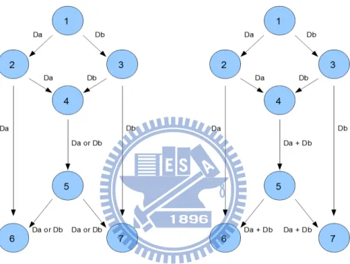
Figure 2-2 The standard example for The Network Coding
In the last few years, there is a method named Network Coding that arouse a lot of relative researches. Because this method can improve the efficiency of network transmission and the reliability by a wide margin. We can say that all the research about the Network Coding are derived from the seminal journal of [11], where it was modified that the maximum flow with minimum cut capacity in a common multicast network can only be accomplished by allowing intermediate nodes to merge different data flows, and it's demonstrated by a number of studies in network coding research (e.g. [12], [13] and [14]. ) To disclosed its conceivable means to support higher throughput and robustness, specially where highly volatile networks such as sensor networks, mobile ad-hoc
networks and P2P networks are concerned. Since we want to implement a method which can be applied into the peer-to-peer network, surly we have to draw on this advantage.
The basic idea behind the Network Coding is demonstrated in Figure 2-2. Let us assume that the node #1 wants to send data bits Da and Db at the same time (to say multicast) to the nodes #6 and #7. It is very clear to find out that the link between the nodes #4 and #5 will form a bottleneck. That is, in the sense that not only bit Da is forwarded (in that case the node #6 does not get bit Db), but also bit Db is send (in that case node #7 will receive incomplete information). Because of the minimum cut to each destination equals 2, this one follows that even if the capacity of the network is 2 bits per transmission, this capacity is impossible to achieve unless the node #4 jointly encodes Da and Db, for instance, we can do it through an XOR operation that allows perfectly recovery at the sinks.
2.3 Factory Data
There are many specifications and works for CM data recovery implementation. This Section introduces the target data – calibration table and digital certificates which are very important for CM working properly. Also, the cable architecture and simple protocol stack for a cable modem are sketched in this section.
2.3.1 Digital Certificates
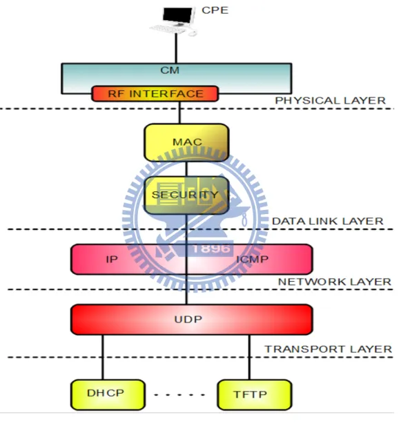
At beginning, in the Figure 2-3 Illustrating a protocol stack for a cable modem, we like to introduce this protocol stack to catch the point why we have to protect calibration table. And referencing to the Data-Over-Cable Reference Architecture [6], we can see that, RF tuner handles the Downstream (DS) and Upstream (US) RF Network in the PHY 3.0 interface. The calibration table is an individualized data table for the modem tuner. For example, about the Downstream calibration table, it provides the basic calibration of the technical possible power levels when the cable modem is receiving Downstream signals. In the other hand, Upstream (US) calibration must
compensate for frequency response of the upstream chain. According to the specification that provided by the chip maker [7], all standard requirements related to US transmitting accuracy are calibrated as follows:
Figure 2-3 Illustrating a protocol stack for a cable modem
The CM is required to report its output power accurately and limited within 2dB. ‧
‧ The step resolution in transmit power for each channel must be 0.5dB or less. The step size accuracy must be within 0.4dB.
‧
All active channels without a power change command must change no more than 0.1db ‧
during a burst even when a power change command is used on any subset of other active channels.
Once we get the calibration data, it will affect the CM signals. The nominal power level of the upstream CM signal(s) will be as low as possible to achieve the required margin above noise and interference. Uniform power loading per unit bandwidth is commonly followed in setting upstream signal levels, under the specific levels which is established by the cable network operator to achieve the required carrier-to-noise and carrier-to-interference ratios [6].
In power-on or reset the provisioning procedures and initializations reveal that a Euro-Modem or Network Interface Unit (NIU) is capable of tuning to the correct channel in the upstream and downstream directions and then it can receive the following basic network parameters. Then, the sign-on and calibration are performed in order to adjust the internal clock and the transmission power of the NIU according to the specific transmission delay and cable attenuation [5]. In the other words, if we lost the calibration tables , the cable modem may encounter malfunction to get link or perform worse throughput than it's own unique calibration tables.
2.3.2 Digital Certificates
According to International Data Corporation (IDC), worldwide Cable Modem Services Market to Reach 69.4 Million Subscribers in 2008, the number of installation is doubled in 2003. As the amount of cable modems being subscribed continues to soar, cable-service piracy through cloning the cable modems is gaining more concern. The CableLabs has created the DOCSIS specification, this specification demands that all of the cable modems should be authenticated with digital certificates, and this requirement is made for address this problem. The digital certificates usually are installed into cable modems during manufacture. All manufacturers who want to continue to sell it's own cable modems, must comply with this specification.
The Cable Modems do not require any user-name or password verification in the same way just like what the other dial up connections do. As we mentioned before, the certificates are hard coded into the Cable Modems when they are built. It is the X.509 digital certificate and it is built up of the some items:
* A serial number
* Cryptographic public key * Ethernet MAC address
* The Manufacture's Identification
The X.509 is verified by the head end equipments, usually it is the Cable modem termination system (CMTS). Once this certificate has been verified, the following data which will sent to user is encrypted in public key. At beginning, the cable modem sends its own X.509 certificate and manufactures certificate. What the verification is checking expiration date, and confirming the name of issuer. And finally that the X.509 signature will be valid under the manufactures certificate public key. In the other hand, the CMTS also uses DOCSIS root public key to test signature and verify the manufacturer certificate. The CMTS responds to ensure the certificate owner is actually the correct owner when the head end has verified the x.509 certificate. To do this, the head end will encrypt the cable modem public key with the authorization key.
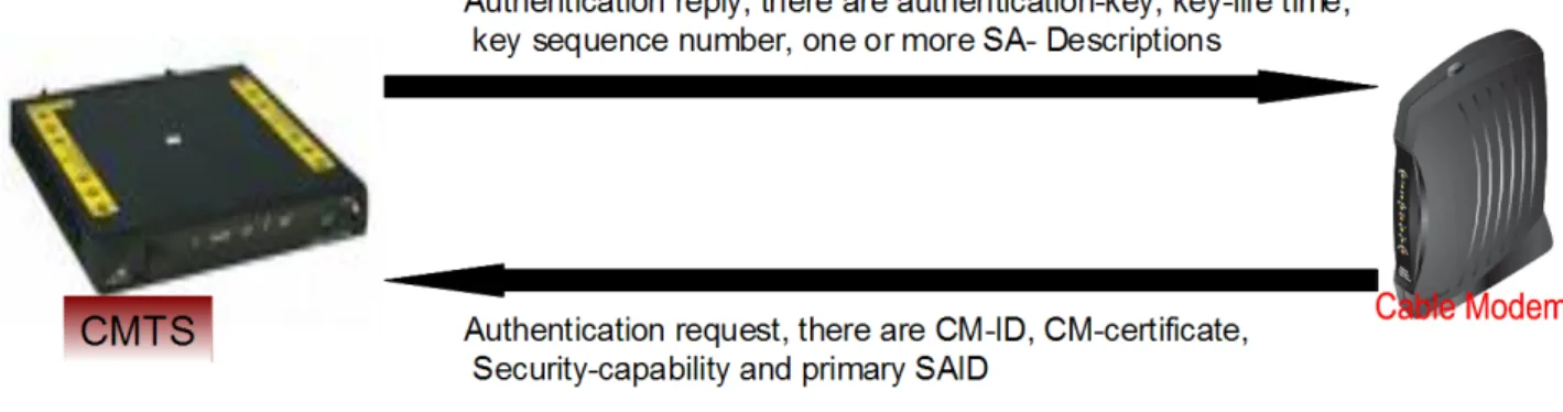
In Figure 2-4 Illustrating how a basic authentication works between the CM and the head
end, we can see the Cable modem must uses it own private key to get the authorization key (if it
was an fake one, it won't have the correct private key). Using this it will generate a Hash-based Message Authentication Code (HMAC) key and reply to the CMTS with this. And the verification of this Hash-based Message Authentication Code key proves the CM has the private key to match the public key.
Figure 2-4 Illustrating how a basic authentication works between the CM and the head end
For the reason that the Cable Modems it would be possible for anyone to acquire the flow data , whatever sending or receiving, with some special packet sniffier or some similar tool like that. The cable operators (to say, MSO) always use a system which is known as Baseline Privacy Plus (BPI+) to solve this kind of problems. The BPI+ encrypts all the packets to ensure that no one can snoop on any transmissions. Surely it also stops the illegal use from someone trying to make any connection to gain free access. The Baseline Privacy Plus encryption must travel with the information where ever it goes. In the Figure 2-4, the CM certificate is the X.509 certificate and the CM-ID is the cluster of the serial number, manufacture ID, MAC address and RSA public key. In this manner, the available maximum encryption is 128 bit. To have a data exchange, first key exchange will be performed. The key exchange uses triple DES as its encryption. This is quite a strong encryption and provides a satisfactory protection to the key exchange. What the algorithm used is a public key exchange. As it used to be, the United States has laws on the level of encryption that is allowed to be exported, thus it is not very easy to get the unique digital certificate keys for our factory to produce our cable modems. That is the point why we have to protect the digital certificates of any our cable modems.
2.3.3 The common arrangement for Recovery and Backup
In our journal mining and research, we did not find any completed solution for implement of
the Network Coding on any kind of embedded system product. But there are some ideas of p2p data sharing based on Network Coding we can refer to. One of these research, Zhu, Li and Guo [21] have generally provide an algorithm which takes full advantage of application-layer overlay networks. In the conventional view, the data can only be replicated and forwarded by overlay nodes. But in their algorithm, linear network coding was applied to application layer multicast. They constructed a multicast graph, which is a subgraph of the rudimentary mesh and a supergraph of the rudimentary tree. It constructed a 2-redundant multicast graph, which means that each node has two disjoint paths to the source. They designed their algorithm such that the costs of link stress and stretch are explicitly considered as constraints and minimized[21]. We refer to this idea, and give the full capability of encoding and decoding data in CM nodes. However, while dynamic membership is a common phenomenon in peer-to-peer networks, this paper did not discuss about how to process peers with dynamic leaving or joining. Although they stand for the point of view that their algorithm essentially doubling the end-to-end throughput in most cases, but the property of 2-redundancy limits the minimum cut of the multicast graph, which in turn limits network throughput. In the other hand, Dimakis, Godfrey, Wainwright and Ramchandran [19] provide a method of fundamental tradeoff between storage and repair bandwidth. They present a regenerating codes method which can significantly reduce the repair bandwidth. Before we can present our solution, we have to put my thinking cap on this paper.
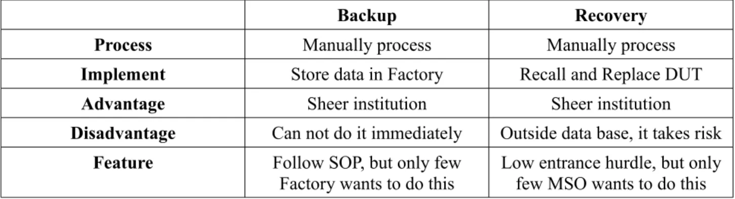
Backup Recovery
Process Manually process Manually process
Implement Store data in Factory Recall and Replace DUT
Advantage Sheer institution Sheer institution
Disadvantage Can not do it immediately Outside data base, it takes risk
Feature Follow SOP, but only few
Factory wants to do this
Low entrance hurdle, but only few MSO wants to do this Table 2-1 The traditional method for maintaining factory data
In this industry, we list the methods for maintaining factory data in Table 2-1. With the previous practical experience, in the backup part, we saved the unique factory data after the product is ready. When any one of these product lost it's original data, the MSO sent it back to factory and give the client another good DUT (device under test) which is been repaired under the traditional recovery method. This arrangement works on the premise that the Factory is capable to maintain these original data files, and the MSO is willing to coordinate with these arrangement. Even if we meets all of the conditions, it still makes the production costs growing. For giving up these disadvantages and enhancing production yield rate, we made this CAROL system and we will demonstrate it in next chapters.
3 System Architecture
In this chapter, we introduce the scheme of the system in detail. In the section 3.1 Overview, we present the system architecture for most important concepts of this system. In section 3.2 The
Back-End Services, we discuss about the necessity of these servers. In section 3.3 The Head End Devices, we describe the main target we want for this system. In section 3.4 The End Nodes, we
portray the way we design the mechanism and what methods we build on each node to make this system working well.
3.1 Overview
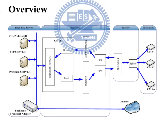
Figure 3-1 Overall System Architecture
With the rapid economic growth , the networking products vendors pay more attention to fast integration for increasing client demands. For this case, the most serious issue is the length of time for a product to be conceived til its being finished and ready for sale. So that the vendor always consider that the shipment date than the quality and reliability of product. The traditional method to recovery factory data is to insert a set of hard code data into the product, but this method will be suitable while the data can be applied to each same kind of product. If the data is being the only one of it's kind (or been individualized), the conventional ways of re-installment (e.g. digital certificates), readjustment (e.g. the calibration table) and backing up with the prepared or the common data of golden board is not suitable. The disadvantages of these traditional methods are time wasting and losing the client trust in the product consistency and quality, thus we want to follow the standard DOCSIS working model and build a system to do the factory data maintenance automatically. With the concept for this system, the client is preferring to fix this issue at their hands. We offer a solution that can meet this condition without giving any instruction to the client.
As we present on Figure 3-1, it includes three main parts for this system: (1) The back-end services. (2) The head end device. (3) The end nodes. We explain the roles for each part in below sections.
3.2
The Back-End Services
In this part includes TFTP server , DHCP server, TOD server and provision server. It makes standard provision as what [6] DOCSIS spec detailed description of design criteria for the end nodes, which can be precede normal online status and provision the vendor data for this system. This was been adapted in this thesis. The end nodes can obtain the related information of recovery system from the provision servers. For DOCSIS spec, the cable modems have to parse the configuration file to get the standard information that helps the cable modems to communicate with the head-end (that is CMTS) and lock the provisioned frequency. And then the cable modems can also get the extended information. After a CM completes it's ranging adjustment, it establishes IP
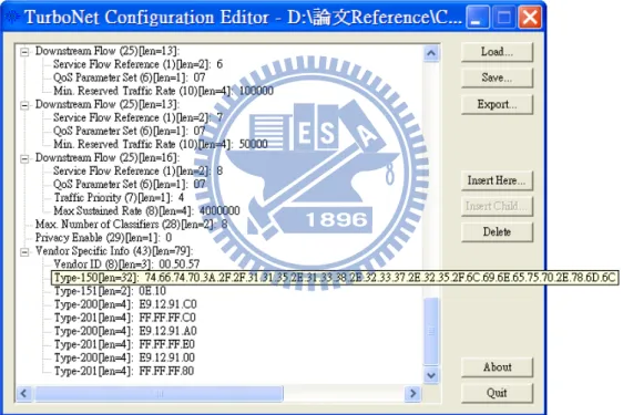
connectivity through using of a DHCP provision. A DHCP server provides the IP services that contain the necessary IP information for the modem to establish IP connectivity, which including its IP address, the IP addresses of the TFTP server for download of the CM configuration file, and other parameters such as the fields must be present in the DHCP request from the CM and MUST be set. In this system, we design all the necessary information in a XML (extensive makeup language) file. This is also a famous method for MSO and vendors to provide their information for their customized services. In Figure 3-2 An example of the CM configuration file, we provision the URL (Uniform Resource Locator) of the XML file as TLV 150 in the CM configuration file.
Figure 3-2 An example for the CM configuration file
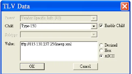
Figure 3-3 TLV data in ASCII
Usually, the configuration file in its final form is a binary file, and typically a configuration tool is used to create the file. There are many public available tools to assist in the creation of DOCSIS CM configuration files. As this tool TurboNet Configuration Editor which we use in this thesis, it is very clear that the CM will receive the TLV 150 value in Hex form. In Figure 3-3 TLV data in
ASCII, the TLV 150 must be translated into ASCII form by the XML parser of each cable modem.
After the CM obtains the necessary information of this system, the CM could comply with ordered operation mechanism of this system. We will discuss this part later.
3.3
The Head End Devices
This part includes the CMTS and the operator aggregation network. The main target we want in this part for our system is setting a basic CMTS system running configuration for the cable modems to enter standard DOCSIS online status. For implementation, we have to setup some basic policies, such as the CMTS interface for the CM to communicate to, private IP address that is used for the CM to talk to the CMTS, the public IP address which is used for CPE (Customer Premises
Equipment) to talk to the CMTS and this IP address is also assigned so that the CPE can go to the internet, the IP address of DHCP server, type of annex (there are different scan plans between DOCSIS, Euro DOCSIS and Hybrid scan plans), modulation type (e.g. 64qam), the default downstream frequency that must match the up-converter for the CMTS platforms, the power-level of upstream, the default upstream frequency that is set to a clean part of the spectrum and after careful analysis, and the last provision is to enable the cable DHCP functionality so that primary addresses are signed for cable modems and secondary addressed are assigned to remote hosts.
3.4
The End Nodes
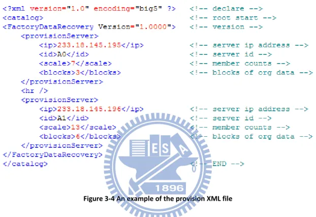
The end nodes are the cable modems. Their job is simple, the main target is just make sure their factory data is safe. That is the CM have to follow our indispensable rules of backup processes to reach this target. After the cable modem establishes IP connectivity through use of a DHCP that is specified by the CMTS. A DHCP server provides the DHCP policy and the IP services that contain the necessary IP information for the cable modem to establish IP connectivity, including its IP address, the IP address of TOD server to synchronize the operation time for the cable modem and the IP addresses of the TFTP server for download of the CM configuration file that includes Network Access Configuration Setting, Class of Service Configuration Setting and End Configuration Setting such as vendor provision data (e.g. TLV 150). Then, the cable modem acquires the XML file by paring this configuration file and access the URL of this XML file. Thus the cable modem can get our provision data to start the backup process. There is an example of the provision XML file in Figure 3-4, what we can provide are the IP address of provision server, the id of the provision server , the scale size and the block number. In some cases, there are several provision servers in the operator aggregation network. For extenuating the burden of the provision server and increasing the efficiency of recovery, we can counterpoise the load by allocate the cable modems into different provision servers. About the scale size, we provision this to the cable modem as how many end nodes will backup it's factory data. The block number is the order that shows how
many blocks of the factory data should be divided and generated. After the cable modems collect these information, the cable modems have the basic rules to comply with this system, and we present the more detail implementation in the next chapter.
Figure 3-4 An example of the provision XML file
4 Evaluations
In this chapter, we starts with proposing how we design this system with clear environment for demonstration. In section 4.1 Nodes Implementation, we portray the way we implement the mechanism and what methods we build on each node to make this system working well. In section
4.2 Program Flow Scenarios, we describe the necessary scenario and flow of this system in detail.
In the section 4.3 Scenario Demonstration, we present the demonstration architecture and how to construct the main architecture. There are some services of this structured recovery system consist in basic distribution and recovery operations, we define overall structure and fail-over mechanisms. And then list the task of services in order to present these important tasks we must implement in this system.
4.1
Nodes Implementation
4.1.1 Allocate the Jobs
According to the above introduction, the cable modems were in charge of the backup process. In order to play an appropriate role and showed their usefulness, we allocate 3 parts of main assignments for each nodes, these implementations should be helpful to anyone who wants to put them into practice on their DOCSIS product:
1. XML parsing. In normal case, the power-up operation of any DOCSIS product can be seen as a step-by-step flow. For the purpose of this part, in our design, we assume that the vendor (operator, also know as MSO) expects to provide the information of environment settings and guiding the nodes to start the process all over the Hybrid Fiber-Cable network by the XML configuration file, just after the step of receiving the DHCP policy.
2. Posting requirements and Receiving requests. In table 4-1 A comparison of information delivery methods of DOCSIS products, there are some famous selections of implementing this part: Broadcasting User Data-gram Protocol (UDP) packets, accessing configuration file (in which a central TFTP server provides a configuration file to a number of cable modems connected together in a Hybrid Fiber-Cable network), and accessing data base server. Because CM certificates is a sensitive data, we can not use this kind of method due to the security issue. About the broadcasting, we have to open one or more ports to listen the special packet which vendor can defined. In this case, the cable modem just accepts the packets that include useful information by filtering the packet contents and discard others. This mechanism acts to prevent performance losing or memory leak. About accessing configuration file, we have a real example. In South Korea, the LG-Powercom as a supplier of high-speed communications access services, adopted the commercial deployment of BigBand's video IP service and IPTV service, it uses the configuration file to provision the On-Screen Display (OSD) information of channels and primary frequencies to lock IPTV channels. For fetching the advantages of these two methods, we make the cable modems parse the XML file to get necessary information. Thus the cable modems were guided to broadcast their requirements and communicate to other nodes, and then transmit the data in our design format based on Network Coding way.
Method Advantage Disadvantage
Broadcasting Fast data transmission Security Issue
Configuration file Easy to maintain System Performance, and
Storage issue
Accessing Data Base Easy to build DB server Maintenance and Security Issue
Table 4-1 A comparison of information delivery methods of DOCSIS products
3. Backup and Recovery. On the basis of the above introduction, we adapt the essence of Network Coding to perform data backup and recovery processes. The data that we delivered, either backup or recovery process, are all underwent encoding and decoding sequence. The idea that how
a system working with Network Coding is well established, it depends on 4 necessary components:
store, forward, encoding and decoding [15][16][17] . There are a lot discussion about the idea of
encoding and decoding processed, but in our journal mining and search, we did not find a completed solution for implement of Network Coding on an exact distributed system. So that we referred these ideas in our own project and offer our implementation below.
Figure 4-1 Using XOR operation to merge different packets into one packet
About the store operation for this system, each cable modem snoops on the HFC network and follow a certain rule that is provisioned by the MSO to accumulate specific amount of overhead packets from other nodes. The overhead packet includes Media Access Control address (MAC address), IP address and backup data of the owner. The MAC address and IP address make the receiver acknowledge that this overhead packet belongs to which cable modem, and this receiver can follow the guidance to prevent from excessive overhead packet inflow from the same sender. That is, the vendor can provision a maximum limit of the overhead packet from same sender as a guideline for the receiver. And it is periodic property of snoops. Of course, the vendor provides a certain period to guide each node snooping.
Concerning the forward part, while a node receives recovery request that includes the index of overhead packet, MAC address and IP address of the requester. Then this node should search it's “stock” to find out is there any overhead packet belong to this requester by matching the MAC address and the index of overhead packet. If there is any available overhead packet for this requester, receiver node should announce the owner and make a tunnel to send it back. Therefore, it
can be conducted through conventional routing protocol.
In Figure 4-1, we can see how a node uses XOR operation to merge different packets into a single packet. In Figure 4-2, there is an idea that we can divide the source data into 3 parts and generate 4 blocks originally from those parts, that is encoding method. Therefore we can decode it by using Gaussian Elimination method and solving these equations. This is a famous idea but there are not much literature discussions about how to implement it actually. Since we must put it into practice, we have to present a executable method to implement this part. It is easy to perform addition and subtraction. Addition and subtraction can be simply performed by XOR operation. In the binary scale, we can just combine two bytes into a single byte, and then calculate any single byte of those two bytes by XOR combination with another byte from other equation. The more difficult parts are performing division and multiplication.
In the beginning, it is confusing that there is harmful in multiplying any packet by the constant. About the encoding operation, we can not acquire the result of division and multiplication. Thus we can not do decoding operation. After searching and designing, we use what is well-known as a Galois Field (GF) to implement this part:
p is a prime number.
The degree of h(x) must be k, and it is an irreducible polynomial in this set. This is a special mathematical construct where addition, subtraction, multiplication, and division are redefined, and where there are a limited number of integers in the field. In binary scale, the overhead packets are regarded as continuous bytes. As we know, the size of an unsigned integer is one byte, and the
specified range is from number zero to 255. We can let the p=2 and k=8 to fit in it, then we can get a limited result after addition, subtraction, multiplication, or division in an 8 bit number. In more detail, it is presented in next section about how to perform addition, subtraction, multiplication, and division of Galois Field with Gaussian Elimination methods.
Figure 4-2 How to Generate blocks from the source data
4.1.2 Encoding and Decoding
Figure 4-3 Illustrating an example for block generation of each byte
About the encoding operation, we simply multiply the packets by the constants according to the above introduction. There is an illustration in Figure 4-3 which demonstrates an example for block generation of each byte, each byte of any packet is regard as an single unit. After we multiply an 8 bit number constant by the single byte from any packet, the cable modems just process these result with addition and then we have the byte from single block.
In the case of multiplication, it is a trifle more complicated [22]. In Galois field for this system[26][27], we take coefficient C and parameter P as two 8 bit numbers, and we take B as an 8 bit product. We can say that, the symbol C is a constant that defined by this system, the symbol P is the single byte of the packet and the symbol B is the the single byte of the block. In the beginning, we set the symbol B to zero. And then make a copy of C and P, which we will simply call C and P in the rest of this algorithm. After that, we do the following five operations (A) to (E) 8 times as a loop. (A) If the low bit of the symbol P is set, XOR the product B by the value of the symbol C. (B) And then Keep tracking of whether the high bit (8th from left) of C is set to one. (C) Rotating
C one bit to the left, then discarding the high bit, and making the value of zero to the low bit. (D) In
this step, we check if the high bit of C had a value of one prior to this rotation, then XOR C with the hexadecimal number 0x1b. (E) Now we Rotating P one bit to the right, discarding the low bit, and making the 8th left most bit have a value of zero. After processing this loop, now has the product of
C and P as the product B.
Figure 4-4 Exponentiation table and Log table using 0xde as the generator
In Figure 4-4 Exponentiation table and Log table using 0xde as the generator, we can do the multiplication more quickly with a log table and anti-log table. That is a basic concept of how to
do multiplication [26][27]. But we have to find out a faster method because we want to implement this in an embedded product. It must save more memory and the NC need to be in real time. There are some numbers in the Galois field, traversing all possible value in the Galois field beside zero that is possible via exponentiation which is defined as repeating multiplication of the same number. These numbers in the Galois field as known as generators. And the multiplication can be done more quickly with 256 byte exponentiation table and 256 byte log table which is produced by one of these numbers as the generator. So that only needs 512 bytes of memory cost in this way of multiplication. In Figure 4-5 using the look-up tables to do the multiplication method in the Galois field, we present how to do the multiplication.
Figure 4-5 Using the look-up tables to do the multiplication method in the Galois field
In normal case, we do not need the division method to do encoding. Therefore, we use Gaussian elimination in GF(28) for decoding so that it is necessary to use division method. We taking the logarithm of C and subtracting the logarithm of P from it, modulo 255 to perform Dividing C by P in the Galois field. Especially, division is done by taking the logarithm of the numerator when the numerator is one, which can be represented as the number 255, and subtracting the logarithm of denominator from 255. In Figure 4-6 using the look-up tables to do the division method in the Galois field, we present how to do the multiplication. As for the implementation of
the Gaussian Elimination method, it is very simple. All we have to do is just replacing the operators (addition, subtraction, multiplication and division) with these methods. And then we can substitute the elements for the parameters.
Figure 4-6 Using the look-up tables to do the division method in the Galois field
4.2 Program Flow Scenarios
In this section, we present the implemented scenarios and system flows in detail. In section
4.2.1 Node Scenarios, we portray all the required scenarios of each node. In the section 4.2.2 Program Flow, we introduce the program flow about main operations.
4.2.1 Node Scenarios
According to the motivation of this system, we want to pass the maintenance tasks to the end nodes. So that we don't have to recall the products which have problems. We design a protocol for the nodes to communicate and behave. There is an diagram in Figure 4-7 illustrating a scenario for
backup process. We can see clearly how the interaction works between the node B, which helps to backup the blocks, and the node A, which sends it's backup block out. First of all, the node A broadcasts it's claim for backup demand to each receiver. If any nodes is ready for intake the block from sender node which needs for help, the helper node (in this case, node B) gets this request. That means there is some free physical space within this helper node. It sends a signal that presents it's will of receiving to the node A over a socket connection directly. When the node A gets this signal, the sender must check the status to figure out if it is necessary to have more backup node. If there are not sufficient backup nodes, the node A sends a chosen blocks with established rule for the receiver. If it's not necessary, the node A just ignore this signal, and after a certain time the node B will terminate this socket for backup need diminished. After sender block has been transmitted and the node B confirms the integrity of this block. The node B must notify the node A that this block has been backup successfully. After that, the node A arranges the owner list which records the relationship between the blocks and the nodes, and then the node A notified the node B this relation is created. Thus the node B arranges the stock list and these blocks from the node A is officially protected by the node B.
Figure 4-7 Illustrating a scenario for backup process
31
Node A Node B
Ask for Help
Response Send Blocks Confirm Receiving Confirm Relation Owner List Stock List
Figure 4-8 Life cycle of a node
Figure 4-8 shows the Life cycle of a node and there are four states: join, post, receive and leave. In the beginning, the node join the system and as we mentioned in previous section, the node
posts it's claim for searching it's own block within network. When it meets certain condition, it enters the receiving states and then goes to finish the backup process. After that, the node keeps listening for any demands from other mode until receives certain signal and then enter post status. It depends on the purpose of the signal, this node will send the correct data out corresponding to the request. We can say that, after the node join this system, the node should backup it's factory data and helps the other nodes in the same network to backup their own factory data until it leave this system. Because of each node has to maintain the owner list periodically, when any node leaves this
32 Leave Join Post Receive Get Claim Power off Power off Meet Condition Meet Condition
system (power off), the other nodes should update their list by starting new processes. Thus, depending on the practical implementation, those state transformations may perform the distribution of the factory data. And any node is supposed can retrieve their factory data by following the guidance of these special lists.
4.2.2 Program Flow
We can see the program process of a node from join this system and help other nodes to saving backup blocks to accomplish the backup task of this node clearly, as shown in Figure 4-9. From previous sections, we introduce that the node is provisioned with some necessary information includes backup condition which are made by the vendor. After acquiring these information and joining the system, the node (the new comer) announces there is one more available node in this system to the other nodes in this system. And this new node also posts it's demand about counting how many it's own backup blocks in this system. If any node in this system has it's backup block, this new node must gets a response with information of the blocks. This searching process continues for a length of time which was provided by the vendor. After that, this node determines if it is possible to recover to the original factory data by currently existent backup blocks or not. If there are not sufficient backup blocks to recover to the original factory data, this node must generate new backup blocks by current factory data, because in this moment maybe the first time this node join this system. If there are enough backup blocks, this node must asks for these online backup blocks holders and have to regenerates whole new backup blocks. And therefore, this node prepares the backup blocks and ready to separate these blocks into parts and gives a share to each nodes over this network. After this node posts it's demand out, this node creates a circulating thread and opens a sock port for listening to any other node which can help this node to backup it's block. After waiting for a certain time, this node starts to help the other nodes to backup. In the meantime, if there is any node respond to this backup demand, this node keeps sending it's backup blocks out and making a list about which node owns what backup blocks. This thread works until the backup task is accomplished.
In the other side, the node services other node before it's stock is full. Without a doubt, the size of the stock is provisioned by the vendor. This condition makes this system more scalable. After that, this node has to maintain it's list that records what nodes have the backup blocks. This polling operation working periodically. In our design, we set a longer time period for this. Because of the cable modems usually do not leave the HFC network frequently. Base on this property, the cable modems do not have to check the completeness of this list frequently. And as this result, we can have better performance of this cable modem. Of course, we let the vendor provide this property before the nodes join the network. This makes this system suitable for other kind of environment. In the way of traditional cable industry, we can decide the maintenance period time by acquiring the MRTG (Multi Router Traffic Graph). For example, if the using habit in a certain region is not keeping the cable modem online for a long time, we can shorten the length of the maintenance period time.
Figure 4-9 Program flow chart
35
Program Node status
Join System
Search Backup Blocks
Check Possibility Searching Timeout Impossible Enough Blocks Recovery and
Regenerate Blocks Regenerate Blocks
Post Demands
Wait for Help
Send Backup Blocks Help Other Nodes Timeout Any node response to this demand If necessary After send Backup completed !
4.3 Scenario Demonstration
4.3.1 Overview
The main purpose of this demonstration is about testing and comparing the traffic
throughput before the recovery operation and after factory recovery operation. The expected result
is the unique factory data of our target cable modem which is fully recovered from our system quickly and flawlessly, so that this cable modem can achieve the ideal throughput.
We take the advantage of a special type network with the idea of a structure which has a normal inflected form called combination network. The combination network was presented in [18] “Network coding gain of combination networks”. And this type of network, when the size of the network increases, can reach the unbounded NC gain which is calculated by the network throughput ratio with NC to without NC. As we know, the combination network is presented as a multicast network with a topology that conforming to a certain principle. For taking this advantage of the combination network, we make the topology of this system as a regular graph which is presented in
Figure 4-10 Topology of the factory data distribution. This topology contains three kinds of
nodes: (1) Factory Data, (2) Generated Blocks and (3) Receiver CM. We explain these nodes in the following descriptions.
(1) Factory Data: In our design, we tar (derived from tape archive and commonly referred to as "tarball") the factory data files into one compressed file (named FactoryData.tgz). And then this factory data can be divided into the continuous parts. So that we can easily get back the original factory data when the source cable modem gets the continuous parts.
(2) Generated Blocks: As we discussed in chapter 3, this system gets the continuous parts by using Gaussian Elimination to solve linear equation method. Since we get the continuous parts from the tared factory data, the source cable modem can generated blocks by linear coding.
(3) Receiver CM: The nodes at the bottom of this topology are the receivers. These receiver
cable modems which is used to receive certain generated blocks from the source cable modem. In our design, the edge vector of a receiver cable modem's incoming edges must be linear independent.
Figure 4-10 Topology of the factory data distribution
As we know, in the random network coding, because of the nodes encode the received data with the random coefficients. That is, the nodes generate random coefficients for the edge functions to determining the outgoing edges' function independently. This kind of feature makes the random network coding maintains a linear coding scheme among the nodes without any control overhead, and become the main advantage [15]. In the other hand, the receiver cable modem's edge vectors of the incoming edges may not be linear independent. But we can not make this system at the risk of fail in factory data recovery.
Here is our solution, we make the coefficients that were generated like the way what the deterministic network coding dose. As we present in the last chapter, the cable modem which is going to backup it's factory data, it receives the coefficients that were assigned by the system. In
Figure 4-10 , the source cable modem can generates the blocks with these assigned coefficients for
it's factory data. There are n (in Figure 4-10, the number is 4) blocks which were generated by the source cable modem with these known coefficients, and relay these to the receiver cable modems.
There are k (in Figure 4-10, the number is 2) multicast capacities of the network, in another word, any one of the receiver cable modems which receives k generated blocks from the source cable modem. Thus, we can see that there are Cn
k receiver cable modems which receive the generated
blocks from the source cable modem.
For this demonstration, the source factory data is divided into three equal continuous parts. The source cable modem generate four blocks with these equal continuous parts by the assigned coefficient. In Figure 4-10, any receiver cable modem gets two generated blocks from the source cable modem. As our design and the rules we set to receiver node, any receiver node can only have one block which is the same as another node. In Figure 4-10, the green block is G1, the purple block is G2, the blue block is G3 and the yellow block is G4. We can see that the leftmost receiver node gets G1 and G2, the second on the left node gets G1 and G3, the third on the left node gets
G1 and G4, the 4th on the left node gets G2 and G3, the second on the right node gets G2 and G4
and the last node gets G3 and G4. For this designed model, there are 7 node available cases: all available, 5 available nodes, 4 available nodes, 3 available nodes, 2 available nodes, 1 available node and no available node. It is easy to understand that if the available nodes more than 4, there are more than 4 kinds of encoded block we can get. Obviously, the source cable modem only needs to get the generated blocks from any two receiver cable modems of these six ones successfully, and then the source cable modem must have three to four encoded blocks. These received blocks are sufficient to return to the original factory data by Gaussian Elimination. We can say that, in this demonstration system, we only need one third of the receiver cable modems which are available to response for the recovery operation, so that 1/3 is our required availability.
Since we consider the issue of the receiver cable modem is unavailable, it is taken for granted to think over the status, when the source cable modem is out of this system in some cases, there should have a method to ensure the distributed blocks available in the network. Let us consider about this case, we have to guarantee the online nodes have enough distributed blocks for maintaining the factory data. In our concept, we must shift the missed blocks to any available
stocks. For implement details, there is a synoptic and schematic diagram in the Figure 4-11 Off line
scheme. And we are going to present the solution below.
Figure 4-11 Off line scheme
We let the nodes N1, N2, N3 and N4 be the cable modems in the network, and all nodes distribute the source factory data in this network already. These are either source nodes or receivers. In some cases, N2 enters the off line status. For keep enough numbers of receiver cable modems, as we present in past chapter, the source cable modems N1, N3 and N4 sending maintain message and detect the generated blocks in N2 is unavailable for recovery operation. To this step, all of these source cable modem enter the post status, broadcast it's requirement to look for a appropriate receiver cable modem to take the place of the node who leaves. Base on the maintain list, the source cable modems have to give a judgment on the selected receiver cable modem which been percolated through the responded message from all the available nodes in this network.
4.3.2 Implementing Services
There are some services of this structured recovery system consist in basic distribution and recovery operations, defining overall structure and fail-over mechanisms. For arriving the concepts we purposed earlier, some tasks must be accomplished. We like to define these tasks for implementing this system, and then present a table lists all the necessary tasks below for quick reference. It is all in the following Table 4-2 Task list.
• Define size: This service is helpful for reaching the research objectives which is mentioned before. According to different conditions of network, we design a service to accept the setting that provisioned from head-end server.
• Timer: Because of any end nodes must ensure the integrity of the distributed blocks, that is the node must keep the owner list traceable. We implementing a method named seeker for this purpose. Any node can trace the distributed block by this service. And the periodic confirmation time of tracing must use the setting assigned from provision server.
• Define topology: The speed of distribution and recovery is affected by the topology. For determining the replication set and the neighbor set, the node interface with routing information must be implemented.
• Node initialization: Responding to the system design, we implement a method named Init-Handler to take care of the join operation. The node can retrieve available environment configuration with this method. After that the node can really comply this topology and play it's role good.
• Join operation: When any node accomplished the initialization, the node is ready to join this network. We implement the corresponding actions of the working flow, and we design the format of correlative messages for node-to-node communication.
• Distributing operation : In this case, the node creates appropriate amounts of blocks and