Abstract—This paper presents a novel compliant motion controller design for an omni-directional mobile robot. In this design, an external force observer is developed based on measuring motor current and speed without using an expensive force/torque sensor. The mobile robot has a handrail to assist the elderly to walk safely and stably. In this application, adaptive motion compliance is required in accordance with the applied force of the user. Practical experimental results show that the compliance of the walking helper can be adjusted by setting dynamic coefficients of the overall dynamical system. It was demonstrated that the external force observer successfully detected the pushing as well as pulling force of a user on the handrail. The velocity of the omni-directional walking helper is adjusted according to the inferred motion intent.
I. INTRODUCTION
n a future aging society, it is very likely that many elderly people will live alone at home. Healthcare and improving the quality of life of the elderly will soon become an important issue of technology development. For most aged people, physiological and memory degradation cause special needs of nursing at home and hospitals. However, many countries face lack of nursing manpower, especially for the elderly care. This situation motivates many research institutes to develop elderly-care smart environment and service robots. Among many types of elderly-care robots, a walking helper is one of the most attractive.
Walking helpers can be categorized into passive and active types. A passive walking helper with brake control features providing support for the elderly people. It has some advantages such as simple structure, low cost, and higher safety. However, a passive walking helper does not have actuators to propel the walking helper; hence it has a load problem in use. On the contrary, an active walking helper is equipped with motors to drive the robotic vehicle. Load in this case is not a problem in practice. Furthermore, one can add various sensors on an active type walking helper to enhance its intelligent behaviors. However, one needs to consider safety issues of active type walking helpers. The safety design of active type walking helpers is more important than the case of passive ones.
Manuscript received March 1, 2009. This work was supported by the National Science Council of Taiwan R.O.C., under grant NSC-96-2628-E-009-162-MY3, and the Ministry of Economic Affairs under grant 95-EC-17-A-04-S1-054.
Kai-Tai Song and Chen-Yang Lin are with Dept. of Electrical Engineering, National Chiao Tung University, Hsinchu, Taiwan (phone: +886-3-5721865; fax: +886-3-5715998; e-mail: ktsong@ mail.nctu.edu.tw).
In recent years, various walking helpers have been developed in research laboratories. Kosuge Lab in Tohoku University has developed several models of passive and active walking support systems, such as RT Walker, Walking Helper and Omni RT Walker [1-6]. These walking support systems not only have the capacity to control the robot’s velocity by means of measuring the force/torque a user put on the robot, but also have the ability of navigation, fall detection, obstacle avoidance and weight compensation. A walking support system developed by Dubowsky et al, at MIT, termed Personal Aid for Mobility and Monitoring (PAMM) system, has two prototypes: SmartCane and SmartWalker. The PAMM has functions of navigation, obstacle avoidance and health monitoring [7-8]. It has a six-axis force/torque sensor mounted under the handle to infer the user’s intent. Care-O-bot II developed by Fraunhofer Institute Manufacturing Engineering and Automation (IPA) can remind the user of events and access to internet [9-11], in addition to navigation and health monitoring functions. A smart elderly walking support system developed by Tsai et al.[12] has the ability of self localization, optimal path planning, remote-control operation, voice command, and internet access.
We summarize important desired functions of a walking helper from the related works. Physical support of the elderly under various usage conditions is most important in the design of a walking helper. Among these functions, compliance to the user’s motion is the key issue. Current solutions counting on the force/torque sensor are still too expensive for practical applications. This study aims to develop a complaint motion control scheme without using a force/torque sensor. The motion control of the platform is investigated in order to provide the user a support in a safer manner. We will explain the prototype design and system architecture of the developed walking helper. Computer simulation results and practical experimental validation of the compliant motion controller will be presented.
II. DESIGN OF THE WALKING-HELP ROBOT
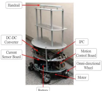
An active type walking helper has been designed and constructed for experimental study. An omni-directional mobile platform with four omni-directional wheels was adopted considering human's omni-directional mobility. Figure 1 shows a recent photo of the walking helper with a dimension of 60×45×89.3 cm3 and weight of 44.6Kg. As shown in Fig. 1, motors and wheels are arranged in 120° apart and installed in the lower part of the robotic platform. Motion control boards, current sensor board and batteries are placed
A New Compliant Motion Control Design of a Walking-Help Robot
Based on Motor Current and Speed Measurement
Kai-Tai Song,
Member, IEEEand Chen-Yang Lin
I
The 2009 IEEE/RSJ International Conference on Intelligent Robots and Systems
Fig. 1. A photo of the walking-help robot
in the second tier. An industrial PC (IPC) and a DC-DC converter are placed on the third tier. On the top tier a handrail is provided for the user to handle the walking helper. In this paper, we propose a method to infer the user's motion intent by means of force estimation. Instead of using an expensive force/torque sensor, a force/torque estimation scheme has been developed by using motor currents and angular velocities. Angular velocities can be obtained from shaft encoders. A current sensing board has been designed for the motor current measurement. Figure 2 shows the current sensing system. Hall current sensor LTS 25-NP was selected for the current sensing design. The motor currents are converted into analog voltage. A microcontroller and analog-to-digital converter (ADC) are used to convert analog voltage to an 8-bit digital value. The current sensor board communicates with on board IPC via RS-232 serial link. The calibration test results show that a linear response is obtained in the current measurement.
A. Kinematic Model
Figure 3 depicts the kinematic model of the walking helper. First, a rotation matrix is defined such that
⎥ ⎦ ⎤ ⎢ ⎣ ⎡ − = δδ δδ δ cos sin sin cos ) ( R (1) where δ is the rotation angle. In Fig. 3, α is the angle between XR and wheel-1(W1)’s main axis. P0 is the position of the center of mass of the robot with respect to the world coordinate frame, i.e. P0= [xG yG]T. Pi is the position of wheel i with respect to the robot center of mass when the robot heading angle equals zero, such that
⎥ ⎦ ⎤ ⎢ ⎣ ⎡ ⋅ = ⎥ ⎦ ⎤ ⎢ ⎣ ⎡ = 0 1 ) ( i i i i i y L x θ R P , i=1~4 (2)
Fig. 2. Motor current sensing design.
Fig. 3. Kinematics of the robotic platform
where Li is the distance from each wheel to the center point as show in Fig. 3. We have L1=L2=d1 and L3=L4=d2. Hence, Pi, i=1 ~ 4 can be found such that
⎪ ⎪ ⎩ ⎪ ⎪ ⎨ ⎧ − − = ⋅ − − = − = ⋅ + = = ⋅ − = − = ⋅ − = T T T T T T T T d L d L d L d L ] cos sin [ ] 0 1 [ ) 2 / ( ] cos sin [ ] 0 1 [ ) 2 / ( ] cos sin [ ] 0 1 [ ) 2 / ( ] cos sin [ ] 0 1 [ ) 2 / ( 2 4 4 2 3 3 1 2 2 1 1 1 α α π α α α π α α α α π α α π α R P R P R P R P
The position vector of each wheel with respect to the world coordinate frame can be expressed as:
i
i P R P
r = 0+ (θ) , i=1~4 (3) We can find the velocity vector of each wheel such that
i i i dt d r P R P v = ( )= & +0 &(θ) , i=1~4 (4) Then we denote the normal vector Di of each wheel's tangential direction as follows:
i i i L R P D ) 2 ( 1 π = , i=1~4 (5)
Hence, we have the following four vectors: ⎩ ⎨ ⎧ − = − − = − = = T T T T ] sin cos [ , ] sin cos [ ] sin cos [ , ] sin cos [ 4 3 2 1 α α α α α α α α D D D D
Then, each wheel's speed can be obtained such that
i T T i i T i T i i P R D P R R D D R v V ) ( ) ( ) ( ) ( 0 θ θ θ θ & & + = = (6)
Thus, each wheel's speed is expressed as:
⎪
⎪
⎩
⎪
⎪
⎨
⎧
+
−
+
−
=
+
+
−
+
−
=
+
−
−
−
−
=
+
+
+
+
=
)
sin(
)
cos(
)
sin(
)
cos(
)
sin(
)
cos(
)
sin(
)
cos(
2 4 2 3 1 2 1 1θ
α
θ
α
θ
θ
α
θ
α
θ
θ
α
θ
α
θ
θ
α
θ
α
θ
&
&
&
&
&
&
&
&
&
&
&
&
d
y
x
V
d
y
x
V
d
y
x
V
d
y
x
V
G G G G G G G G (7)It can be rewritten in matrix form
⎥ ⎥ ⎥ ⎦ ⎤ ⎢ ⎢ ⎢ ⎣ ⎡ = ⎥ ⎥ ⎥ ⎥ ⎦ ⎤ ⎢ ⎢ ⎢ ⎢ ⎣ ⎡ = ⎥ ⎥ ⎥ ⎥ ⎦ ⎤ ⎢ ⎢ ⎢ ⎢ ⎣ ⎡ θ θ ω ω ω ω & & & G G V W W W W y x R R R R V V V V ) ( 4 3 2 1 4 3 2 1 T , ⎥ ⎥ ⎥ ⎥ ⎦ ⎤ ⎢ ⎢ ⎢ ⎢ ⎣ ⎡ − − + − + − − − − − + + = 2 2 1 1 ) sin( ) cos( ) sin( ) cos( ) sin( ) cos( ) sin( ) cos( ) ( d d d d V α θ α θ α θ α θ α θ α θ α θ α θ θ T (8)
where
ω
i, i=1 ~ 4, denotes the angular velocity of each wheel and RW is the wheel's radius. TV(θ) is the transformation matrix that transforms the velocity of center of the robot in the world frame to the speed of each wheel. We change the coordinate system form world coordinate frame to robotic coordinate frame; then the inverse kinematic transformation matrix MV can be obtained such that⎥ ⎥ ⎥ ⎦ ⎤ ⎢ ⎢ ⎢ ⎣ ⎡ = ⎥ ⎥ ⎥ ⎥ ⎦ ⎤ ⎢ ⎢ ⎢ ⎢ ⎣ ⎡ = ⎥ ⎥ ⎥ ⎥ ⎦ ⎤ ⎢ ⎢ ⎢ ⎢ ⎣ ⎡ θ ω ω ω ω & & & R R V W W W W y x R R R R V V V V M 4 3 2 1 4 3 2 1 (9) where
Fig. 4. System architecture of the walking helper.
⎥ ⎥ ⎥ ⎥ ⎦ ⎤ ⎢ ⎢ ⎢ ⎢ ⎣ ⎡ − − − − = 2 2 1 1 cos sin cos sin cos sin cos sin d d d d V α α α α α α α α M .
The forward kinematic transformation MV+ can be obtained such that. T V V T V V V R R V V V V y x M M M M M 1 4 3 2 1 ) ( , + − + = ⎥ ⎥ ⎥ ⎥ ⎦ ⎤ ⎢ ⎢ ⎢ ⎢ ⎣ ⎡ = ⎥ ⎥ ⎥ ⎦ ⎤ ⎢ ⎢ ⎢ ⎣ ⎡ θ& & & (10)
B. Control System Architecture
The architecture of the walking helper control system is illustrated in Fig. 4. Four current sensors are employed to measure currents of four motors and the results are sent to the on-board IPC. A low pass filter works to filter out high frequency fluctuations in the current measurement. Motor speeds are measured using motor shaft encoders. The Motor currents and rotational speeds are feedback to the external force observer, which estimates the external force exerted by the user. The compliant motion controller is responsible to calculate velocity commands in response to the estimated user force. The DSP-based motion control system executes the velocity commands on the walking helper. An odometer provides velocity, location and traveling distance of the walking helper.
III. COMPLIANT MOTION CONTROL
We hope that a user can easily handle the walking helper. Thus the walking helper is expected to have a kind of passive behavior. The idea is to include in the control loop the force exerted by the user on the walking helper. The purpose is to control the walking helper's velocity via the exerted force. When a user exerts external force to the walking helper, the mobile platform will respond to it through the speed of motion. If the external force is larger, the speed is faster and vise versa.
A. External Torque Observer
We propose to detect the motor currents and rotation speeds to observe the walking helper's external force. First, the torque observer of a single motor is described. The relationship between the motor electromagnetic torque Tm and current
i
a is such thata b
m K i
T = ⋅ (11) where Kb is torque constant. Denote the friction torque Tf, external torque Text, inertia Jt and damping Bt on the rotor, then we have: f ext m t t B T T T J
ω
&+ω
= − − (12) whereω
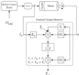
is motor speed. We want to observe external torque of a single motor. Figure 5 depicts the block diagram the external torque observer of single motor. The motor current and speed are feedback to the observer as inputs. Then output equation can be obtained[13] such thatω ω ω ω ω G J T B G J i K G s G T B s J i K G s G T t f t t a b f t t a b ext − − − + ⋅ + = − − − ⋅ + = ) ( ) ( ˆ (13)
In (13), the parameter G is related to the dynamics of the force estimation. The larger G enables the observer to estimate the external torque fast and stable.
B. Proposed External Force Estimation Scheme
The omni-directional walking helper is composed of four motors, thus we extend the control structure of single motor to the body of the walking helper. In other words, we want to derive the relationship between the center force of the robot and tangent forces of the four wheels. As shown in Fig. 6, tangent force of each wheel is denoted as
Fig. 5. Block diagram of the external torque observer
FW = [f1, f2, f3, f4]T, while force of the robot center is FO =[FX, FY, NZ]T. The center force is calculated by the following equation: ⎥ ⎥ ⎥ ⎦ ⎤ ⎢ ⎢ ⎢ ⎣ ⎡ − − − − = = 2 2 1 1 cos cos cos cos sin sin sin sin , d d d d f W f O α α α α α α α α M F M F (14)
In (14), Mf is the translational matrix that transforms the tangent force of each wheel to the center force of the robot. We denote Fm the force generated by the motors. Figure 7 is the block diagram of external force observer of the walking helper. In the figure, Mr=diag(Mx, My, Iz) and Dr=diag(Dx, Dy, Dz) are the inertia and damping coefficients of the walking helper respectively. Vr is the velocity of walking help. Ff is the friction force. Hence the external force, Fext is estimated such that: r r O f r r r r O m O O ext sGG F G MV DV F G MV F + − − − + = ( ) ˆ (15) C. Compliance Controller
As the external force exerted by the user is obtained, we can calculate the desired velocity of the vehicle. The velocity commands are then sent to the motion control board to generate the desired motion of the walking helper. In order to design the compliance required for the walking helper, a dynamic model is adopted for velocity generation. As shown in (16), Md and Dd are desired mass and desired damping of the overall system. Fuser is the force exerted by the user, Vr is calculated following the dynamics equation such that
user r d r dV DV F M & + = (16)
Figure 8 shows the compliance control architecture. We feedback the motor currents and rotation speeds to the external force observer. The compliance controller calculates the velocity of the walking helper according to the estimated exerted force. The wheel speed is calculated using inverse kinematics and the motion control system assures the walking helper to achieve the velocity. The parameters Md and Dd can be adjusted to a desired passive behavior to satisfy the user's need.
Fig. 7. External force observer of the walking helper.
Fig. 8. System architecture of compliant motion controller.
IV. EXPERIMENTAL RESULTS
A. Parameters of the Walking Helpers Controller
The external force observer needs the mass, damping and friction force of the walking helper. The mass of our experimental walking helper is Mr = diag(44.6, 44.6, 1.38). But the damping and friction force are not easy to obtain. A motion test was conducted to obtain these values. In the motion experiment, the external force caused by the damping and friction can be expressed such that:
r r f ext r r O r r O m O O ext sGG G G V D F F V M V M F F + = − + + = ˆ ) ( ˆ (17)
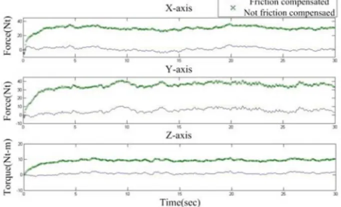
From (17), we can obtain Ff and Dr through experiment. In the experiment, we let the walking helper move along X-axis, Y-axis, and rotate about the Z-axis respectively; then use (17) to estimate the force. Because (17) does not consider the friction force and damping, so the external forces will not be zero, as shown by the bold green lines in Fig. 9. The Ff = [20, 22.77, 6.93]T Nt.s/m and Dr = diag(50.2, 36.2, 3.8) Nt.m.s/rad are identified by practical experiments and applying (17). The Dr and Ff values were then inserted in (15). The force estimate results are near zero as expected, see the thin lines in Fig. 9.
B. Compliant Motion Experiment
In the compliant motion experiment, the user pushed the handle of the walking helper, the walking helper moved forward in accordance with the user’s force. When the user ceased to push the walking helper, the walking helper stopped. Figure 10 shows the scenario of the experiment. We set the desired mass Md = diag(11, 11, 1.2), desired damping Dd = diag(10, 36, 2) and speed limit 0.4 m/sec. When the user pushed the robot in X-axis, Y-axis, and rotation in Z-axis respectively, the external force was estimated, as shown in Figs. 11(a)(c)(e). The compliant motion controller calculates the velocity to produce the walking helper motion, as shown in Figs. 11(b)(d)(f). It can be seen from the figure that if the external force is zero, the motor currents is practically zero as expected.
C. Influence of the Desired Mass
We set different desired mass to 30 kg and 44.6 kg with the same desired damping, 10 Nt⋅s/m. Figure 12 shows the estimated external force and the walking helper speed response of these two situations. Figs.12 (a)(c) show the estimated force and speed response for the desired mass of 30 kg, while Figs.12 (b)(d) are for the case of the desired mass of 44.6 kg. We find that for almost the same external force input, the speed responses are different. The larger the desired mass, the slower the speed response. Therefore One can change the mass parameter to adapt to the user’s passive motion preference.
Fig. 9. Experimental results of force estimate with and without friction and damping compensation.
Fig. 10. The robot and experimental environment.
V. CONCLUSION AND FUTURE WORK
In this paper, a novel compliant motion controller design for an omni-directional motion platform has been presented. In this design, an external force observer works based on measuring the motor currents and speeds without using a force/torque sensor. Experimental results show that the compliance of the omni-directional walking helper can be adjusted by setting dynamic coefficients of the overall dynamical system. The external force observer effectively detects the external force exerted by a user on the walking-help robot. For the walking helper to work on inclines, a gravity compensator will be added to the control structure in the future. We will add a laser scanner to provide environmental information to the robot and the obstacle avoidance function will be integrated to the motion platform. Health monitoring functions will also be investigated in order to provide more intelligent behaviors to the walking helper.
Fig. 11. Experimental results of force and velocity responses in compliant motion.
Fig. 12. Influence of various desired masses.
REFERENCES
[1] Y. Hirata, T. Baba and K. Kosuge, “Motion control of omni-directional type walking support system "Walking Helper",” in Proc. of IEEE international Workshop on Robot and Human Interactive Communication, Millbrae, California, USA, 2003, pp.85-90.
[2] Y. Hirata, A. Hara and K. Kosuge, “Passive-type intelligent walking support system RT Walker,” in Proc. of the 2004 IEEE/RSJ International Conference on Intelligent Robots and Systems, Sendai, Japan, 2004, pp.3871-3876.
[3] Y. Hirata, A. Hara and K. Kosuge, “Motion control of passive-type walking support system based on environment information,” in Proc. of the 2005 IEEE Inter. Conf. on Robotics and Automation, Bacerlona, Spain, 2005, pp.2932-2937.
[4] Y. Hirata, A. Muraki and K. Kosuge, “Motion control of intelligent passive-type walker for fall-prevention function based on estimation of user state,” in Proc. of 2006 IEEE Inter. Conf. on Rob. and Auto., Orlando, FL, USA, 2006, pp. 3498-3503.
[5] N. Nejatbakhsh, Y. Hirata, K. Kosuge, “Passive omnidirectional walker-design and control,” in Proc. of the 2005 IEEE Inter. Conf. on Advanced Robotics, Seattle, WA, USA 2005, pp.518-523. [6] O. Chuy, Y. Hirata, Zhidong Wang and K. Kosuge, “Motion control
algorithms for a new intelligent robotic walker in emulating ambulatory device function,” in Proc. of the 2005 IEEE International Conference on Mechatronics and Automation, Niagara Falls, Canada, 2005, pp. 1509-1514.
[7] S. Dubowsky, F. Genot, S.Godding, H. Kozono, A. Skwersky, H. Yu and L. S. Yu, “PAMM - A robotic aid to the elderly for mobility assistance and monitoring: A "helping-hand" for the elderly,” in Proc. of IEEE Inter. Conf, on Rob. and Auto., 2000, pp.570-576. [8] M. Spenko, H. Yu and S. Dubowsky, “Robotic personal aids for
mobility and monitoring for the elderly,” IEEE Trans. on Neural Systems and Rehabilitation Engr, Vol. 14, No. 3, pp.344-351, 2006. [9] J. Manuel, H. Wandosell and B. Graf, “Non-Holonomic Navigation System of a Walking-Aid Robot”, in Proc. of IEEE international Workshop on Robot and Human Interactive Communication, Berlin, Germany, 2002, pp.518-523.
[10] B. Graf, “Reactive navigation of an intelligent robotic walking aid,” in Proc. of IEEE International Workshop on Robot and Human Interactive Communication, 2001, pp.353-358.
[11] B. Graf, A. Hans, J. Kubacki and R.D. Schraft, “Robotic home assistant Care-O-bot II,” in Proc. of IEEE EMBS/BMES Conference, TX, USA, 2002, pp. 2343 – 2344.
[12] C.-C. Tsai, Y.-S. Huang, Y.-C. Wang and S.-M. Hu, “Design and Implementation of Nursing-Care Walking Assistant for the Elderly,” in Proc. of 2005 Chinese Automatic Control Conf., Tainan, Taiwan, 2005, pp. 210-215.
[13] T. Murakami, R. Nakamura, F. Yu and K. Ohnishi, "Force sensorless impedance control by disturbance observer," Record of the Power Conversion Conf., Yokohama, Japan, 1993, pp.352 - 357.