國
立
交
通
大
學
電機與控制工程學系
博
士
論
文
MPEG-4/H.264 視訊壓縮標準於嵌入式系統之最佳化研究
The Study of Optimization Approaches for MPEG-4/H.264 Video Processing
Standards on Embedded Systems
研 究 生:彭信元
指導教授:吳炳飛 教授
MPEG-4/H.264 視訊壓縮標準於嵌入式系統之最佳化研究
The Study of Optimization Approaches for MPEG-4/H.264 Video Processing
Standards on Embedded Systems
研 究 生:彭信元 Student:Hsin-Yuan Peng
指導教授:吳炳飛 教授 Advisor:Prof. Bing-Fei Wu
國 立 交 通 大 學
電 機 與 控 制 工 程 學 系
博 士 論 文
A DissertationSubmitted to Department of Electrical and Control Engineering College of Electrical Engineering
National Chiao Tung University in partial Fulfillment of the Requirements
for the Degree of Doctor of Philosophy
in
Electrical and Control Engineering May 2008
Hsinchu, Taiwan, Republic of China
MPEG-4/H.264 視訊壓縮標準於嵌入式系統之最佳化研究
學生:彭信元
指導教授:吳炳飛 教授
國立交通大學電機與控制工程學系博士班
摘 要
本論文中提出許多最佳化之方式將MPEG-4 與 H.264 視訊壓縮技術分別實現在以 ARM、
FPGA 搭配之 SoC 開發平台與以 ARM、DSP 為基礎之雙核心平台,透過硬體、韌體及軟體上 在壓縮流程上的最佳化,將複雜的演算法實現在運算能力較低之嵌入式系統中,並得到良好的 壓縮效果。 在MPEG-4 硬體最佳化上,本論文提出一種階層式的動態估測演算法,透過數學的分析以 及實驗的結果來決定哪些步驟對於壓縮品質之影響力較為廣泛,推導一快速、高品質且適合用 硬體實現之演算法。且其運算複雜度僅為全域搜尋法之3.91%。搭配此演算法,以 ARM 配合 FPGA 的實現方式來進行 MPEG-4 即時壓縮系統的研究。此系統可依據使用者要求動態調整輸 入以及輸出影像參數,可有效提高其應用性。 而在 H.264 於 ARM/DSP 雙核心嵌入式平台的實現上,推導一適合影像式車用防盜系統之 動態估測演算法,可用低複雜度的運算方式,有效克服車輛行駛中因外在光源變化等因素導致 視訊壓縮品質下降的問題,並且針對車輛影像特性將動態估測流程作動態更新,能在重點區域 保持良好壓縮品質,同時大幅增加運算速度。除此之外,本論文亦將H.264 壓縮流程做最簡化, 利用記憶體配置管理、雙核心CPU 工作分配以及 DSP 特有指令等最佳化技巧,成功移植入低 成本且高穩定之嵌入式系統中。 除了將演算法以硬體與軟體等不同的方式進行最佳化之外,本論文亦將實現之系統實際運
用於由交通大學自製研發之Taiwan iTS-1 智慧車中,搭配了 Zigbee 無線傳輸以及 3.5G/3G 手
機程式設計,當車輛正在移動時,本系統可偵測駕駛員前方、後方以及兩側盲點區域之車道線 以及車輛距離,並以直覺的方式提供資訊。而當車輛停妥後,若有歹徒強行闖入,系統則會即 時發送警告訊息至使用者,車主即可利用手機隨時隨地瀏覽愛車情況,並可馬上提供警方歹徒 之面貌。本論文之宗旨在利用各種最佳化方式,於嵌入式系統上實現動畫壓縮技術,並將其與 智慧型車輛結合,讓駕駛員、乘客以及車輛都能有更安全的環境。
The Study of Optimization Approaches for MPEG-4/H.264 Video
Processing Standards on Embedded Systems
Student:Hsin-Yuan Peng
Advisors:Prof. Bing-Fei Wu
Department of Electrical and Control Engineering
National Chiao Tung University
ABSTRACT
In this dissertation, several optimization approaches for implementing the MPEG-4 visual and the H.264 video processing standards on an ARM/FPGA Soc platform and an ARM/DSP dual-core embedded system are addressed. By the modification of the compression procedures in hardware, firmware and software, the complex algorithms are successfully ported to the low computing power embedded devices, and good encoding performance is obtained.
In the MPEG-4 hardware optimization, an efficient hierarchical motion estimation algorithm (HMEA) is proposed. With mathematical analyses and the experimental results, the search steps, which can dominate the image quality, are designed in order to develop a high-speed and good quality architecture that is suitable for hardware implementation. The operational complexity of HMEA is only 3.91% of the full search block matching algorithm, and with HMEA, a register-based platform-independent MPEG-4 co-processor (RPIMC) is designed. RPIMC can change the input and the output parameters of the bitstreams by adjusting the value of the registers dynamically to widen its applications.
For implementing the H.264 framework on an ARM/DSP dual-core embedded system, an adaptive motion estimation algorithm (AMEA) especially for the vehicle surveillance videos is developed. By easy manipulations, AMEA can overcome the coding quality degradation due to the changing environments, and it can update the search procedure adaptively according to the video characteristics in a moving object to maintain the performance in the region of interest. Moreover,
the platform-based acceleration techniques, such as the memory organization, the dual-core communication and the program modification, for H.264 are also presented.
In addition to algorithm optimization in hardware, firmware, and software, the developed system in this dissertation has been successfully tested in the intelligent vehicle, Taiwan iTS-1, developed in National Chiao Tung University, on the real road environment in Taiwan. Cooperating with the warning system, which can detect the vehicles and the lane marks in front/rear directions and blind spot areas, the Zigbee wireless communication and the 3.5G/3G mobile phone programming, the system can provide the distance information of the surrounding cars to the drivers through a friendly intuitive graph, and it will produce the warning signal when lane departure. After parking, if there exists intruders, the system will send a notification message to the users, and they can browse the real-time images of the vehicles by their mobile phones anytime and anywhere. The main contribution of dissertation is to provide a safer environment to drivers, passengers and vehicles at all time using several optimization approaches for implementing complex video processing standards on embedded systems.
Table of Contents
摘 要... I ABSTRACT ... II Table of Contents ...IV List of Figures ... VII List of Tables...IX
Chapter 1. Introduction ... 1
1.1 Motivation... 1
1.2 The Proposed Optimization Approaches and Their Contributions... 4
1.2.1. Efficient Hierarchical Motion Estimation Algorithm and Its VLSI Architecture ... 5
1.2.2. Register-Based Platform-Independent MPEG-4 Co-Processor... 6
1.2.3. Adaptive Motion Estimation Algorithm for Vehicle Surveillance Videos... 7
1.2.4. Real-Time Driving Assist and Surveillance System ... 8
1.3 Organization ... 9
Chapter 2. Efficient Hierarchical Motion Estimation Algorithm and Its VLSI Architecture ... 10
2.1. Introduction ... 10
2.2. Hierarchical Motion Estimation Algorithm... 16
2.2.1. Downsampling Methods ... 16
2.2.2. Framework of HMEA ... 24
2.2.3. Experimental Results... 30
2.3. Proposed VLSI Architecture ... 33
2.3.1. Overall Architecture... 33
2.3.2. Downsampling ... 36
2.3.3. DAU ... 40
2.3.4. DAU Processing at Each Level ... 43
2.3.5. Half-Pel Search ... 48
2.4. Implementation Results ... 50
Chapter 3. Register-Based Platform Independent MPEG-4 Co-Processor and Its System-Level Design ... 53
3.1 Introduction ... 53
3.2 The Architecture of RPIMC... 57
3.2.1. The Hardware Pipeline Scheduling... 58
3.3 System-Level Design ... 66
3.3.1. The Software Architecture of REMR... 67
3.3.2. The FPGA Prototype of REMR ... 69
3.4 Implementation Results ... 72
3.4.1. The Chip Implementation Results... 72
3.4.2. The Performance Comparison... 74
Chapter 4. An Adaptive Motion Estimation Algorithm for Vehicle Surveillance Videos ... 76
4.1 Introduction ... 76
4.2 The Analysis of The Vehicle Surveillance Videos... 80
4.2.1. Lighting Effects... 80
4.2.2. The Coding Performance degradation due to the lighting effects ... 85
4.2.3. The MV characteristics ... 88
4.3 Adaptive Motion Estimation Algorithm... 90
4.3.1. Histogram extension algorithm (HEA) ... 91
4.3.2. AMEA in ROI ... 94
4.3.3. AMEA out of ROI... 100
4.3.4. The complexity analysis of AMEA... 101
4.4 Implementation Results ... 103
Chapter 5. A Real-Time Driving Assist and Surveillance System ... 107
5.1 Introduction ... 107
5.2 The Innovative Functional Scheme of DASS ... 113
5.2.1. Active Vision-based Warning Supports ... 114
5.2.2. H.264 Driving Status Recorder ... 116
5.2.3. Burglarproof with Mobile Surveillance... 117
5.3 The Module and Architecture of DASS... 118
5.3.1. Lane Departure Warning Module... 119
5.3.2. Forward / Backward Collision Warning Module ... 119
5.3.3. Blind Spot Warning Module ... 120
5.3.4. The Software Architecture of VSS... 121
5.4 H.264 Encoder with AMEA on VSS ... 122
5.4.1. Cooperation of ARM and DSP... 123
5.4.2. H.264 Encoder Optimization... 126
5.4.3. The Mobile Phone Programming ... 130
5.5 Implementation Results ... 132
5.5.1. Lane departure and vehicle detection algorithms ... 134
5.5.4. The Performance and Functionalities of VSS ... 140
5.5.5. Comparisons... 143
Chapter 6. Conclusions and Perspective... 145
6.1 The hardware-based HMEA and RPIMC ... 145
6.2 The software-based AMEA and DASS... 146
List of Figures
Fig. 2-1. The hierarchical frame structure ... 16
Fig. 2-2. Examples of 2D-DWT downsampling: (a) frequency bands after two-level DWT decomposition; (b) original Akiyo image; (c) reduce the Akiyo image 50% in both width and height; (d) reduce the Akiyo image 25% in both width and height ... 19
Fig. 2-3. The relationship between the 2D-DWT and the downsampled images ... 19
Fig. 2-4. The correlation coefficients between the adjacent images for averaging filter, left_top method, Haar DWT, and Antonini 9/7 DWT in (a) Flower garden (b) Stefan (c) Mobile... 23
Fig. 2-5. The hierarchical search procedure. ... 25
Fig. 2-6. The overall architecture of HMEA. ... 35
Fig. 2-7. The timing diagram of HMEA for level 0 ... 36
Fig. 2-8. Down sampling four rows of level 2... 37
Fig. 2-9. The downsampling hardware block diagram for level 2... 38
Fig. 2-10. The downsampling hardware block diagram for level 1... 39
Fig. 2-11. The architecture of a 2D DAU... 42
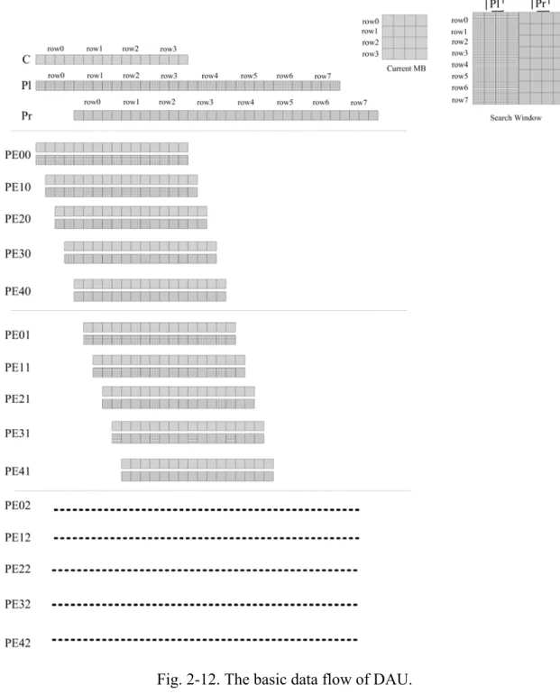
Fig. 2-12. The basic data flow of DAU. ... 43
Fig. 2-13. The timing diagram of HMEA for level 1 ... 44
Fig. 2-14. The timing diagram of HMEA for level 2 ... 45
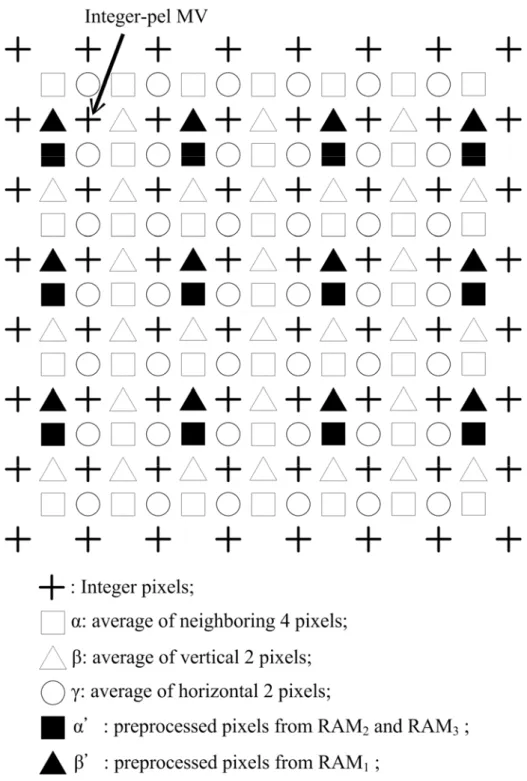
Fig. 2-15. Interpolation for half-pel search... 49
Fig. 3-1 The overall architecture of RPIMC... 58
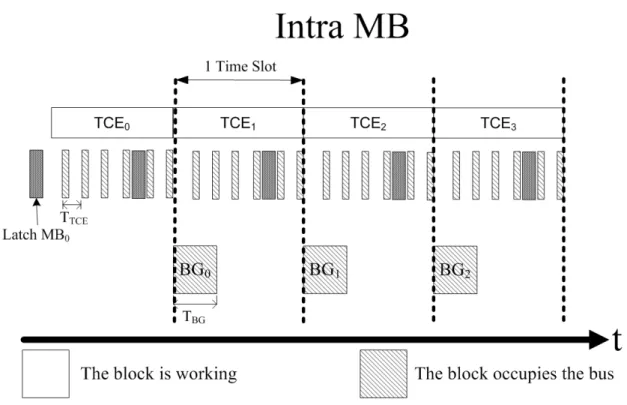
Fig. 3-2 The intra MB scheduling ... 59
Fig. 3-3 The inter MB scheduling ... 61
Fig. 3-4 The flow chart of the controller ... 62
Fig. 3-5 The state of the external memory... 66
Fig. 3-6 The system overview of REMR... 67
Fig. 3-7 The software architecture of REMR ... 68
Fig. 3-8 The architecture of REMR in ARM Integrator... 71
Fig. 3-9 The chip layout ... 73
Fig. 4-1. The vehicle surveillance image with ROI... 80
Fig. 4-2. The tunnel which will cause lighting effects. ... 82
Fig. 4-3. (a)The brightest image, (b)The darkest image of V1... 83
Fig. 4-4. The Mk of each frame of V1 ... 83
Fig. 4-5. (a)The brightest image, (b)The darkest image of V2... 84
Fig. 4-6. The Mk of each frame of V2 ... 85
Fig. 4-7. The correlation coefficients between each frame pairs of V1... 86
Fig. 4-9. (a) The Mk of each frame ,(b)The correlation coefficients between each frame pairs of V0 ... 88
Fig. 4-10. The manipulated MVs ... 89
Fig. 4-11. (a) depicts the probability of the magnitude of MVs in and (b) out of ROI for all frames of V0. ... 90
Fig. 4-12. (a) the histograms of the input frame before and (b) after the pre-processing. ... 94
Fig. 4-13. AMEA search diamonds SD0, SD1 and SD2. ... 96
Fig. 4-14. Closed-loop adaptation process for AMEA. ... 97
Fig. 4-15 The correlation coefficients between each frame pairs of (a)V1 and (b)V2 before and after HEA... 105
Fig. 4-16 The Mk of each frame of (a)V1 and (b)V2 before and after HEA... 106
Fig. 5-1 The detection zones of LVWS, BSWS and VSS ... 113
Fig. 5-2 The overall system block diagram of DASS... 114
Fig. 5-3 The flowchart of the active real-time vehicle detection and lane departure warning system... 116
Fig. 5-4 The flowchart of the full-time recorder... 117
Fig. 5-5 The flowchart of the mobile surveillance system ... 118
Fig. 5-6 The estimated lateral offset... 119
Fig. 5-7 The software architecture of VSS ... 122
Fig. 5-8 The proposed H.264 encoding data path... 124
Fig. 5-9 The synchronization of audio and video encoding ... 125
Fig. 5-10 Communication between related threads ... 126
Fig. 5-11 The original H.264 encoding control flow... 127
Fig. 5-12 The proposed H.264 encode faster control flow ... 128
Fig. 5-13 The state chart of server-push we addressed... 131
Fig. 5-14 The processing flowchart of the program on a mobile phone... 132
Fig. 5-15 TAIWAN iTS-1 ... 133
Fig. 5-16 The monochromatic CCD mounted behind the (a) front (b) rear windshields... 133
Fig. 5-17 The monochromatic CCD mounted on the (a) left (b) right side view mirrors... 134
Fig. 5-18 The USB CCD mounted behind the right front windshield ... 134
Fig. 5-19 Detection results in front-rear views from LVWS... 135
Fig. 5-20 Detection results in side views from BSWS ... 135
Fig. 5-21 Detection results in different conditions ... 136
Fig. 5-22 Distance and location on screen... 137
Fig. 5-23 The experimental results of (a)applying deblocking filter and (b)not applying it ... 138
Fig. 5-24 The GUI developed on mobile phones. ... 142
Fig. 5-25 The screen of our program on Nokia mobile phone. ... 142
List of Tables
Table 2-1 The comparison of the video quality between various downsampling methods for left-top, Haar’s DWT,
Atonini’s 9/7 DWT, and the averaging filter in dB. ... 22
Table 2-2 The PSNR performance and the complexity analysis in different number of the MV candidates at the coarsest level... 26
Table 2-3 The PSNR performance and the complexity analysis in different LSRs in the middle and the finest level. ... 27
Table 2-4 The comparison of the complexity, including half-pel search, between FSBMA, nSS, MRMC-4, MRMCS and HMEA in different search ranges... 32
Table 2-5 The PSNR comparisons of various fast-search algorithms in dB. ... 32
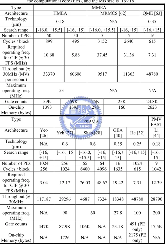
Table 2-6 The comparison between HMEA with other architectures for MMEA, FSBMA, and PMVFAST. The search range among each frameworks are different, the equivalent gate counts includes control and address generation overheads as well as the computational core (PEs), and the MB size is 16×16. ... 52
Table 3-1 The register banks ... 62
Table 3-2 The chip specification of RPIMC ... 74
Table 3-3 The performance comparison between the software model and RPIMC in dB ... 74
Table 3-4 The performance comparison between other MPEG-4 chips and RPIMC... 75
Table 4-1 The encoding quality comparisons of the different videos in dB... 87
Table 4-2 The quality comparisons of the blocks in and out of ROI of different video sequences in dB. ... 104
Table 4-3 The normalized processing speed comparisons of the different videos ... 104
Table 5-1 PSNR and FPS evaluation for intra predication with different block sizes... 129
Table 5-2 PSNR and FPS evaluation for intra predication with different directional predictions... 129
Table 5-3 Performance comparison with deblocking filter ... 138
Table 5-4 PSNR and MCPS Comparison... 139
Table 5-5 PSNR and comparison ratio comparison ... 140
Table 5-6 The specification of VSS. ... 141
Chapter 1.
Introduction
With the wide spread adoption of technologies such as digital televisions, internet streaming videos and DVD-Videos, video compression has become an essential component of broadcast and entertainment media. The MPEG-4 visual and the H.264 video coding standards are commonly used in internet and wireless transmission applications, and they can provide higher flexibility and compression ratio than the earlier MPEG-1, MPEG-2, and H.263 ones [1]-[5]. However, the computational complexity of these two superior frameworks, MPEG-4 visual and H.264, are also much larger. PCs with strong CPUs and inexhaustible power supplies can easily implement them, but the need of human beings can not accept that. People nowadays want to record the real-time videos to take notes or share with their friends using their handheld devices, such as portable video recorders, digital cameras, and mobile phones. These equipments are always using low-power CPUs in order to save their battery life. Therefore, the study of optimization approaches for MPEG-4/H.264 video compression standards on embedded systems is essential to port the complex algorithms on the consumer electronics while maintaining the image coding quality. In this dissertation, several algorithmic, practical and integrated methods in both the software and the hardware point of view, and the system-level design techniques for embedded platforms are presented.
1.1 Motivation
services, with audiovisual information, playing an increasingly important role. Today’s existence of tens of millions of digital audiovisual content users and consumers is tightly linked to the maturity of such technological areas as video and audio compression and digital electronics and to the timely availability of appropriate coding standards. These standards allow the industry to make major investments with confidence in new products and applications and users to experience easy consumption and exchange of content. In this environment, the Moving Picture Experts Group’s (MPEG’s) remit is to develop standards for compression, processing and representation of moving pictures. It has been responsible for a series of important standards starting with MPEG-1 (compression of video and audio for CD playback) and following on with the very successful MPEG-2 (storage and broadcasting of ‘television-quality’ video and audio). MPEG-4 is the latest standard that deals specially with audio-visual coding, and it can provide a more flexible and efficient update to the earlier MPEG-1 and MPEG-2 standards.
On the other hand, the Video Coding Experts Group (VCEG), a study group of the International Telecommunications Union (ITU), was also responsible for the first widely-used videotelephony standard (H.261) and its successor, H.263, and initiated the early development of the H.26L project [6]. The two groups set-up the collaborative Joint Video Team (JVT) to finalize the H.26L proposal and convert it into an international standard (H.264/MPEG-4 Part 10) published by both ISO/IEC and ITU-T.
With the widespread popularity of handheld multimedia devices, such as digital video recorders (DVs), digital cameras (DCs), personal digital assistants (PDAs), and mobile phones, in these days, people rely on the mobile technology more and more.
To integrate these consumer electronics into a multi-functionalities equipment is a world wide trend, and the need for capturing audio-visual information for various purposes is becoming a main stream. The MPEG-4 visual and the H.264 video processing standards can provide amazing compression ratio while maintaining excellent video quality, and the existence of them respond to the emerging requirement of mankind.
However, due to the cost, the size, the battery life, and many restrictions, these portable instruments are always implemented with CPUs with low operating frequencies or application-specific integrated circuits (ASICs) with small size and lesser power consumptions. Therefore, to development high performance video encoders with extremely tremendous computational complexities on these embedded platforms are great challenges that must overcome for new generation communications. Hence, the optimization approaches which can reduce the calculation load and increase the execution speed of these two frameworks, MPEG-4 visual and H.264, for the embedded systems are definitely necessary, and they can be separated into three major categories, one is the hardware, another is the software, and the other is the platform-based methods.
All of these three perspectives are efficient optimization approaches, they focus on the different implantations and applications, and they have distinct advantages. For general purpose video encoders, which have fixed parameters, such as input image resolution and framerate, using hardware accelerators is appropriate, since they can reduce the overall power consumption and cost. However, if the users want to have high performance in the changing environments, like vehicles or outdoors, the software video compressors can provide flexible inputs, and they can perform the data
pre-process to get better quality according to the various utilizations. Nevertheless, it requires a CPU which is power enough to execute the programs and the energy requirement will be also raised. Both hardware and software techniques need to be integrated into platforms to accomplish a system, so platform-based manners are also essential to reduce the system overhead. The off-chip memory organization, the usage of direct memory accelerator (DMA), and the communications between processors are all acceleration methods that depend on system-level designs.
A high performance video recorder has not only a fast compressor, implemented by hardware or software, but also a good system peripherals controller that coordinate the input and the output data scheduling well. Therefore, the hardware, the software, and the platform-based optimization approaches are all required to form an efficient system in terms of coding speed, cost and battery life, and the overall cooperation between these aspects will be further discussed in this dissertation.
1.2 The Proposed Optimization Approaches and Their
Contributions
The most complex part of the video coding standards is the motion estimation (ME), it spends about 70% of the total encoding time, and it dominates the image quality. The straight forward method is full search block matching algorithm (FSBMA), but its computational complexity is too high to be implemented on embedded systems. Therefore, in order to simplify the search procedure while maintaining the image quality using different implementation frameworks, i.e. hardware or software, according to the system requirements is one of the main
contributions of this dissertation. They are briefly introduced in the following sub-sections.
1.2.1. Efficient Hierarchical Motion Estimation Algorithm and Its VLSI
Architecture
As mentioned in Section 1.1, for general purpose video encoder, a hardware accelerator is suitable for reducing the cost and increasing the performance. Therefore, an efficient hierarchical ME algorithm (HMEA), and its high speed VLSI architecture are developed [7][8]. HMEA is a kind of multi-resolution ME algorithm, and it can simplify FSBMA by downsampling the original frame to three levels. At the smallest resolution, the least two motion vector (MV) candidates are selected using FSBMA. At the middle level, these two candidate MVs are employed as the center points for small range local searches. Then, at the original resolution, the final MV is obtained by performing a local search around the single candidate from the middle level. HMEA adopts an averaging filter, by analyzing several downsampling methods, to downsample the original image, which is the first step of the estimation progress. When superior quality is obtained in the anterior part of the ME, the refining procedures can be significantly shorter and the complexity can be reduced accordingly. HMEA can achieve almost the same coding performance as FSBMA in terms of peak signal-to-noise ratio (PSNR), but HMEA is faster. Moreover, A high-speed pipeline VLSI architecture with a reasonable chip area for HMEA is also addressed. It utilizes an efficient two dimensional (2D) processing element (PE) array to compute the sum of the absolute differences (SADs), and the search range can be
implementation because the number of the computations for each macro block (MB) is fixed. HMEA is faster and more area-efficient than numerous existing full-search and multi-resolution architectures.
1.2.2. Register-Based Platform-Independent MPEG-4 Co-Processor
When HMEA is successfully implemented, the rest manipulation blocks of the MPEG-4 video processing standard are started to develop. After all, a compressor needs not only to reduce the redundancy in spatial domain, but also in the frequency one. Moreover, the statistical encoding and the bitstream packaging functions are also necessary to encode raw data to the standard format. Therefore, a register-based platform-independent MPEG-4 co-processor (RPIMC) is designed to accentuate the efficiency of HMEA [9][10]. The goal of RPIMC is not merely to be a normal video encoder, and it tries to be as flexible as the software one using firmware/hardware hybrid methodology. RPIMC can transfer and receive the image data in all kinds of bus matrices with suitable wrappers for being easily integrated into other platform, and it can adjust the data types of the input and the output streams by modifying the relative registers. The main idea of RPIMC is to provide a programmable MPEG-4 encoder which can easily integrated into any platforms to satisfy the demand for various applications by modifying the input frame size, the input frame rate, and the output bitrate. The main controller of RPIMC will automatically calculate the internal loops of the pipelines for encoding, and will read the data in the corresponding memory with the correct image resolution based on these registers, respectively. Therefore, the manufacturers who need MPEG-4 encoders can easily integrate
proper register settings.
1.2.3. Adaptive Motion Estimation Algorithm for Vehicle Surveillance
Videos
Although RPIMC tries its best to be as flexible as the software coders, it still has limitations. If the input video is influenced by the noise, RPIMC can not pre-process that and will lead to poor performance. Besides, if the information in the dedicate part of the image are important, and clear results are required, RPIMC doesn’t have this feature. Therefore, an adaptive motion estimation algorithm (AMEA) especially for the vehicle surveillance videos is developed to overcome the problems [11]. The total amounts of vehicles and the traffic accidents are increasing year by year, but the efficiency of finding the real reasons, which cause the tragedies, is still low. If a system, which can record the situations inside the cars, is adopted, the evidences can be provided to the police officers as soon as possible. In the real environments, the videos contain several problems, such as the different weathers, and the changing of the light sources, and these will lead to the heavy computation and the bad video quality. On one hand, in order to overcome the drawbacks, AMEA applies an easy histogram extension algorithm (HEA) to pre-process the images to keep the images stable and increase the estimation accuracy greatly. On the other hand, the purpose for the monitoring information is to provide clear faces of the intruders, so the images are separated into two parts, in and out of the region of interest (ROI). In ROI, AMEA can maintain the coding quality using the least numbers of manipulations, and meantime it can also enormously reduce the computational complexity for the blocks
1.2.4. Real-Time Driving Assist and Surveillance System
The environment inside vehicles has many restrictions, such as limited installation space, finite power supply when cars is parked and the noise effects due to the vibrations, so the stable and low power consumption embedded platform based on TI OMAP5912 is chosen to implement a dual-core DSP-based H.264 encoder (DDBE) with AMEA. DDBE combines an ARM9 RISC and a DSP core [12]. On one hand, ARM can perform the system control functions, such as image capturing, file transformation, user interface, process scheduler, and etc. On the other hand, DSP focuses on the H.264 algorithm, which requires more computing power than the peripheral controllers. Two kinds of optimization techniques, platform-independent algorithmic and memory optimizations, are applied to reduce the computational complexity. The advantage of DDBE is that it can execute the H.264 algorithms, and record the bitstream into a file or transmit them through the internet by the streaming server on ARM at the same time.
DDBE should be applied in the intelligent vehicles since thousands of people are killed or injured in the accidents which are mostly caused by the carelessness of humans. Therefore, a real-time driving assist and surveillance system (DASS) is integrated with a warning system, which can notify the driver of the approaching vehicles in all directions and the lane departure, and DDBE [13-16]. The driving status, such as the situation around the vehicle and the drivers’ behaviors, can be recorded by DASS, so the police officers can reconstruct the scene easily. Furthermore, the increasing numbers of stolen cars is also an important issue so
to prevent thieves [17-20]. The goal of DASS is to provide a total solution which integrates the innovative functions in an embedded system to offer the users full-time protection, and DASS has been successfully implemented and fully tested by the real road environment in Taiwan.
1.3 Organization
The rest of this dissertation is organized as follows. Chapter 2 presents the efficient hierarchical motion estimation algorithm and its VLSI architecture. The register-based platform-independent MPEG-4 co-processor and its system-level design will be proposed in Chapter 3. In Chapter 4, the adaptive motion estimation algorithm for vehicle surveillance videos will be addressed. The real-time driving assist and surveillance system will be described in Chapter 5. Finally, some conclusions and future research perspectives will be stated in Chapter 6.
Chapter 2. Efficient Hierarchical Motion
Estimation Algorithm and Its VLSI
Architecture
This chapter addresses the development and hardware implementation HMEA using multi-resolution frames to reduce the computational complexity. Excellent estimation performance is ensured using an averaging filter to downsample the original image. At the smallest resolution, the least two MV candidates are selected using FSBMA. At the middle level, these two candidate MVs are employed as the center points for small range local searches. Then, at the original resolution, the final MV is obtained by performing a local search around the single candidate from the middle level. HMEA exhibits regular data flow and is suitable for hardware implementation. An efficient VLSI architecture that includes an averaging filter to down-sample the image and two 2D semi-systolic PE arrays to determine the SAD in pipeline is also presented. Simulation results indicate that HMEA is more area-efficient and faster than many full-search and multi-resolution architectures while maintaining high video quality. This architecture with 59K gates and 1,393 bytes of RAM is implemented for a search range of [-16.0, +15.5].
2.1. Introduction
The most complex part of popular video compression standards, including MPEG-4, MPEG-2, and MPEG-1, is ME [1][3][4]. The goal of ME is to remove the
temporal redundancies existing in adjacent frames, and the block-matching algorithm is used as a method for most of the video coding systems. It is used to find a block which is most similar to a current block within a pre-defined search area in a reference frame, and it dominates the encoded image quality, the compression ratio, and the computation time. The reference frame is a previously-encoded frame from the sequence and is before the current frame in the display order. The straight forward method to perform the operation is FSBMA, but it requires lots of manipulations due to its high complexity. Usually, FSBMA spends about 70% of the total encoding time, and this heavy computational load limits the performance of the encoder in terms of encoding speed and power consumption. Therefore, many VLSI architectures for FSBMA have been proposed for fast hardware implementation [21]-[29]. In these architectures, a result is observed that although FSMBA is easy to be implemented and can provide better compression quality, it has either large chip area or low speed. Traditionally, frameworks of FSBMA are block-level pipelined, where one reference block is considered at a time and the parameters are reset before starting another reference block. Compared with them, the frame-level pipelined FSBMA implementations can achieve nearly 100% fully pipelined computation by exploiting the explicit frame-level parallelism [30]. He et al. proposed a new two-level nested Do-loop FSBMA and a novel 2D array ME architecture [31]. However, its PE array
size is fixed to 2
N , and will limit the capability. Therefore, they extend their design
[32], and develop a scalable improved frame-level pipelined architecture, which reduce the internal FIFOs and increase the speed of [31]. It contains 1,024 PEs and can manipulate an MV in 256 cycles within a search range of [-16, +15].
(SEA) [33]-[35], partial distortion elimination (PDE) [36], the winner-update algorithm [37], and the advanced diamond search algorithm (DSA) [38] are proposed to reduce the computational heavy load of FSBMA while maintaining its quality. However, the irregular data flow makes these algorithms suitable only for software implementation owing to their inability to determine exactly how many of SAD operations are required to calculate a single MV. Huang et al. proposed a new block matching algorithm called the global elimination algorithm (GEA), which is modified from SEA [39][40]. GEA has a more regular data flow than SEA. Moreover, the processing cycles are fixed, no initial guess is needed, and the conditional branch that applies when a candidate block cannot satisfy the criterion for early termination is removed. Although GEA is easily implemented and capable of providing good quality, it requires an operating frequency of 19.42 MHz to manipulate the MVs of CIF image in real-time.
Besides, in order to refine the accuracy of DSA, several new algorithms, such as motion vector field adaptive search technique (MVFAST) [41], predictive MVFAST (PMVFAST) [42], and enhanced predictive zonal search (EPZS) are proposed [43]. MVFAST improve DSA in both terms of visual quality and speed up by initially considering a small set of predictors. Unlike DSA where only a large moving diamond pattern was considered, MVFAST also introduced a smaller moving diamond. PMVFAST uses basically the same architecture and patterns as MVFAST does, but a significant difference of PMVFAST compared to MVFAST is the way the small versus the large diamond is selected. Dissimilar to MVFAST where motion was characterized as low, medium, or high by considering the largest motion vector candidate, in PMVFAST a different selection strategy, which can improve the overall speed of the algorithm by using the large diamond less often, is used. Furthermore,
EPZS that improves upon PMVFAST by considering several other additional predictors in the generalized predictor selection phase of PMVFAST. EPZS also selects a more robust and efficient adaptive threshold calculation where as, due to the high efficiency of prediction stage, the pattern of the search can be considerably simplified. However, the disorderly early termination of the search procedure still leads to the poor performance. An architecture, which combines PMVFAST and EPZS, is developed, and it can be configured to support different search patterns, and independent SAD computations [44]. The implementation results show that it requires 1,042 cycles to manipulate an MV, and it does not entirely complete the PMVFAST and EPZS due to their high complexity.
Another ME algorithm that can significantly reduce the computational complexity by decreasing the number of computations is the hierarchical motion vector search algorithms (HMVSA), including three-step search (3SS) [45], new three-step search [46], and four-step search [47], which separate the estimation process into several levels, and the numbers of levels is fixed. HMVSA has regular data flow, and the total execution time is constant, so HMVSA is suitable for hardware implementation. However, HMVSA suffers from a considerably lower PSNR than FSBMA, especially when the motion field is large and complex.
A particular HMVSA is developed to solve this problem, MMEA, whose basic idea is to make an initial coarse estimate and then refine it. Conventional MMEAs are usually implemented in two ways. One is to use a variable search area at each level [48]-[51], and the other is to apply a constant search area [52]-[54]. In the former, an MV candidate is obtained from a large search area at the coarse level and the candidate becomes the search center of the next level, which has a smaller search area.
A larger search area corresponds to a more accurate MV, but the extent of motion may increase with the search area. Therefore, the first MV candidate may not be a good estimate, and will yield an incorrect result at the next levels. Although the latter approach can partially solve this problem since the search area is constant at all levels, the MVs may be less robust against noise.
The above MMEAs that choose only one MV candidate fall easily into the local minimum, so numerous algorithms that combine the scheme with a multiple MV candidate search have been proposed [55]-[59]. However, these methods have a high computational cost to get the prediction performance close to that of FSBMA, because multiple MV candidates are required for local searches at each level. In these algorithms, the method for down-sampling the image is to select one of four pixels in a block. This method may be inappropriate if the block is the edge of a video object, and will influence the image quality, in terms of PSNR of the image. Accordingly, more MV candidates are required to yield an encoded image quality close to that of FSBMA. If the MV candidates are not only chosen by the basis of minimum SAD, such as by the neighborhood relaxation scheme in [58] or the four candidates, which correspond to four differently superblocks[51], the complexity will be increased.
Many hardware architectures for MMEA have been implemented [49], [60]-[63]. In [49], the framework is at the expense of a chip area because the on-chip memory is large. Each multi-resolution level in [60] and [61] has its own specific systolic array, which cannot commonly be applied among different levels, reducing the performance in terms of logic gate usage. [62] has a small chip area, but the reuse of data and the SAD computations are inefficient. Therefore, the overall speed is reduced, and it will limit its applications that require low operating frequency to save the power
consumption such as mobile phones and portable multimedia recorders. In [63], although the reuse of data is efficient, a large on-chip memory is required.
In this chapter, HMEA and its VLSI architecture are proposed. The main contributions of this chapter are to analyze several downsampling methods, discuss which method is suitable for hardware implementation, and derive a high speed pipeline VLSI architecture. HMEA adopts an averaging filter to downsample the original image, which is the first step of the estimation progress. In these hardware frameworks for MMEA [49], [60]-[63], the downsampling methods are not addressed due to the hardware cost. However, when superior quality is obtained in the anterior part of the ME, the refining procedures can be significantly shorter and the complexity can be reduced accordingly. HMEA can achieve almost the same coding performance as FSBMA in terms of PSNR, but HMEA is faster. The MV will be more credible and the search speed is higher as the search area increases. Furthermore, the proposed HMEA limits the number of MV candidates to two at the coarse level, and sets the total number of levels to three to solve the significant problem of the local minimum. An averaging filter is employed, so a single candidate at the final level suffices to provide the desired performance.
A high-speed pipeline VLSI architecture with a reasonable chip area for HMEA is also addressed. It utilizes an efficient 2D PE array to compute the SADs, and the search range can be doubled without adding any hardware. The architecture is suitable for VLSI implementation because the number of the computations for each macro block (MB) is fixed. HMEA is faster and more area-efficient than numerous existing full-search and multi-resolution architectures.
2.2. Hierarchical Motion Estimation Algorithm
HMEA can be divided into two parts. One is the averaging filter for down-sampling, and the other is the MV search procedure. The complete algorithm is described as below.
2.2.1. Downsampling Methods
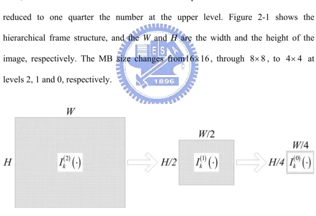
HMEA comprises three resolution levels, from zero to two. Level 0 is the top level, and level 2 is the lowest. The number of pixels at the next lower level is reduced to one quarter the number at the upper level. Figure 2-1 shows the hierarchical frame structure, and the W and H are the width and the height of the
image, respectively. The MB size changes from16 16× , through 8 8× , to 4 4× at
levels 2, 1 and 0, respectively.
Fig. 2-1. The hierarchical frame structure
In block matching algorithm, SAD is an important procedure, and its value at level l can be defined as
( )
( )
( )( )
( )(
)
( ) ( )2 2 16 2 1 16 2 1 1 0 0 , , , l l l l l MB k k i j SAD p q I i j I i p j q − − ⎡ ⎤ ⎡− ⎤− ⎢ ⎥ ⎢ ⎥ ⎣ ⎦ ⎣ ⎦ − = = =∑
∑
− + + , (2-1) where ( )l kI is the kth input image, and l is the level number and l=0, 1, 2.
In (1), the computational complexity of the matching process can be seriously reduced. At level 1, the computational complexity is only one quarter than that at level 2, and that at level 0 is one quarter than that at level 1.
Numerous approaches are available to reduce an image. In this paper, three different methods, left-top, 2D discrete wavelet transform (2D-DWT), and averaging filter are adopted. The comparison of these methods in computational complexity, performance and hardware implementation are discussed. The bicubic interpolation that can provide better performance is not in consideration since its complexity is much more than the other methods. Besides, when it comes to reducing the image with 50% in both width and height, the quality is not as better as it of enlarging the frame.
A. Left-top method
The left-top method is one of the simplest approaches for subsampling an image. For the kth input frame, ( )2
( )
⋅k
I , the upper level images are computed by executing the
following down-sampling: ( )−1
( )
, = ( )(
2,2)
, =1 ,2 l for j i I j i I kl l k , (2-2)frame at level l−1.
In the hardware implementation, the arithmetic operations are not necessary, and the output image can be generated by inputting the original one by specific order directly. The only cycles required are for moving data, and no extra hardware design is essential.
B. 2D-DWT
In image processing, most of the power associated with natural image signals tends to be in the low frequency band. Accordingly, the analysis of the low frequency band must be more extensive than that of the high frequency band. In practical applications, the low frequency band, decomposed from DWT, is further analyzed through second level DWT processing to yield more detail of the analysis signal at the lower frequency band. Such analysis is referred to as multi-resolution. Haar's and Antonini 9/7 Wavelet Transform is used to increase the speed of execution of the wavelet transform [64]. The 2D-DWT is applied as a one-dimensional DWT in the horizontal direction and then another in the vertical direction.
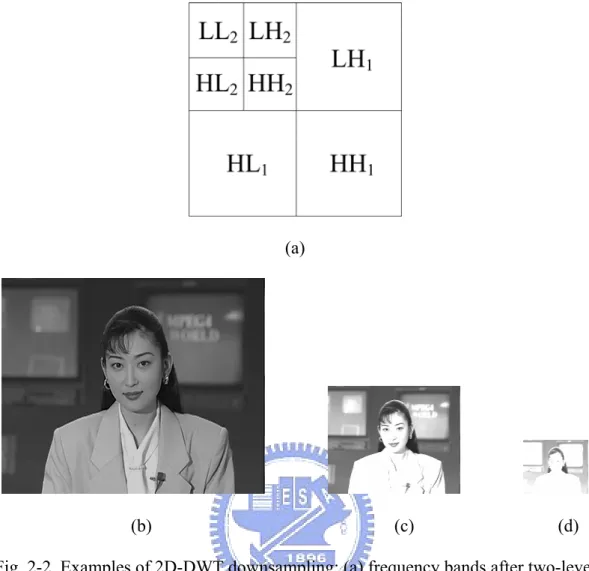
Figure 2-2(a) plots the corresponding locations of the images of the frequency bands decomposed by 2D-DWT. Fig. 2-2(c) and Fig. 2-2(d) shows the subsampled results obtained using the ‘Akiyo’ image, displayed in Fig. 2-2(b), after two levels of DWT processing. Fig. 2-2(c) and Fig. 2-2(d) truncate the values that are above 255 and below 0 for demonstration, but the value are retained in the evaluation progress. As shown in Fig. 2-3, for the kth frame, Ik( )1
( )
i,j and Ik( )0( )
i,j are the LL band of the first and the second order decomposition, respectively.(a)
(b) (c) (d) Fig. 2-2. Examples of 2D-DWT downsampling: (a) frequency bands after two-level DWT decomposition; (b) original Akiyo image; (c) reduce the Akiyo image 50% in both width and height; (d) reduce the Akiyo image 25% in both width and height
Fig. 2-3. The relationship between the 2D-DWT and the downsampled images
computational complexity is heavy because it requires more additions and more multiplications for subsamping one pixel. Secondly, in the normal hardware design, 8 bits are required to store the gray level value of the pixel from 0 to 255. However, the range of the downsamping pixel by 2D-DWT goes beyond 0 to 255, and more bits are necessary. Therefore, the memory bandwidth of the hardware architecture and the chip area will be increased. Although the range of the pixels can be normalized into 0 to 255 to reduce the bandwidth, the extra hardware for normalization is essential. The computational complexity and the die size will be also increased.
C. Averaging filter
This method is the same as the bilinear interpolation that rescale the image with 50% in both width and height. Therefore, the quality of the reduced image can be ensured. For the kth input frame, ( )2
( )
⋅k
I , the upper level images are computed by
executing the following down-sampling:
( )
( )
∑ ∑
+ ( )(
)
= + = − = ×2 1 = 2 1 2 2 1 , , 1 ,2 4 1 , i i m j j n l k l k i j I m n forl I , (2-3) where Ik( )l( )
i,j 1− represents the value at position
( )
j
i , of the kth frame at level l−1.
The hardware implementation for the averaging filter is simple, and only three additions and one bit shift operations are required for subsampling one pixel.
The main purpose of the ME is to eliminate the temporal redundancies existing in adjacent frames. Therefore, the quality will be increased when higher correlation
coefficient exists between the successive images. The correlation coefficient, ρ, is
defined as: ( )
( )
(
)
(
( )( )
)
[
]
( )( )
(
)
∑∑
(
( )( )
)
∑∑
∑∑
− × − − × − = + + i j k i j k i j k k m j i I m j i I m j i I m j i I 2 2 0 1 2 1 0 2 0 1 1 0 , , , , ρ , (2-4)where m1 and m2 are the means of Ik( )0
( )
⋅ and Ik( )0+1( )
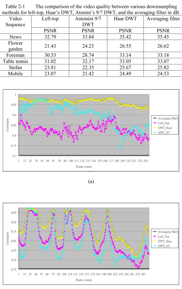
⋅ , respectively.Figure 2-4 shows that the correlation coefficients between the downsampled images. It is observed that the correlation coefficients of the Haar DWT and the averaging filter are almost the same, and are much greater than the left-top and the Antonini 9/7 DWT methods, especially in the video sequences that their backgrounds are more complex. In Table 2-1, the estimation results are depicted, and it shows that the average PSNR of Haar DWT and the averaging filter are similar. Moreover, the image quality of the left-top method is bad, and Antonini 9/7 DWT even gets worse quality than it in some cases. The results indicate that downsampling method plays a very important role in MMEA. The estimation performance of adopting averaging filter significantly exceeds that of the method that considers only the left-top pixel, and can be used to design an efficient down-sampling hardware architecture.
Table 2-1 The comparison of the video quality between various downsampling methods for left-top, Haar’s DWT, Atonini’s 9/7 DWT, and the averaging filter in dB.
Left-top Antonini 9/7
DWT
Haar DWT Averaging filter
Video Sequence PSNR PSNR PSNR PSNR News 32.79 33.84 35.42 35.45 Flower garden 21.43 24.23 26.55 26.62 Foreman 30.53 28.74 33.14 33.18 Table tennis 31.02 32.17 33.05 33.07 Stefan 23.81 22.35 25.67 25.82 Mobile 23.07 21.42 24.49 24.53 0.7 0.75 0.8 0.85 0.9 0.95 1 1 12 23 34 45 56 67 78 89 100 111 122 133 144 155 166 177 188 199 210 221 232 243 Frame counts C or re la tio n Averaging Filter Left_Top DWT_Haar DWT_9/7 (a) 0.35 0.45 0.55 0.65 0.75 0.85 0.95 1 14 27 40 53 66 79 92 105 118 131 144 157 170 183 196 209 222 235 248 261 274 287 Frame counts Co rr ela tio n Averaging Filter Left_Top DWT_Haar DWT_9/7
0.75 0.8 0.85 0.9 0.95 1 1 12 23 34 45 56 67 78 89 100 111 122 133 144 155 166 177 188 199 210 221 232 243 254 265 Frame counts Co rr ela ti o n Averaging Filter Left_Top DWT_Haar DWT_9/7 (c)
Fig. 2-4. The correlation coefficients between the adjacent images for averaging filter, left_top method, Haar DWT, and Antonini 9/7 DWT in (a) Flower garden (b) Stefan
(c) Mobile
The performance of the Antonini 9/7 DWT is worse than that of the Haar DWT is unexpected. Theoretically speaking, the Antonini 9/7 DWT can reserve more information in low frequency band since it adopts higher order filters. However, the statement stands only when the inverse transform, which is not executed in the downsampling procedures, is performed. Therefore, Antonini 9/7 DWT requires higher computational power, but it provides poor quality in the downsampling stage of HMEA. Moreover, if the scaling factor of Haar DWT is replaced by 1/2, the results are exactly the same as the averaging filter, and can get rid of the dynamic range
problem. The reason of the averaging filter outperforms the Haar DWT is that 1 2
is chosen as its scaling factor, and this will cause the inaccuracy of the values of downsampled pixels. Considering both the coding performance and the hardware design, the averaging filter is chosen to down-sample the image in HMEA.
2.2.2. Framework of HMEA
The overall searching process can be separated into three levels. As presented in
Fig. 2-1, when level 2 receives an input image ( )2
( )
⋅k
I , the image will be
down-sampled to ( )1
( )
⋅k
I and Ik( )0
( )
⋅ , where the resolutions of Ik( )1( )
⋅ and Ik( )0( )
⋅ are one quarter and one sixteenth of that of ( )2( )
⋅k
I , respectively. Let the entire search
range at level 2, or Ω , be ( )2
[
− , −1]
w
w . After the original image Ik( )2
( )
⋅ has beendown-sampled, the search procedure, illustrated in Fig. 2-5, begins. Let ( )l
Cur ,
( )l
Pre , SA and k( )l MVn( )l denote the current MB, the previous frame search area, the kth search area and the n-th MV candidate at level l, respectively. The detailed process at each level will be described below.
Fig. 2-5. The hierarchical search procedure.
A. Search at Level 0
Two MV candidates, ( )0
1
MV and MV2( )0 , are manipulated at this level. MV1( )0 is defined as the least MV that obtained by a full search within a given search area, i.e.
( ) ( ) ( ) ( )
( )
p q SAD MV MB q pmin , 0 , 0 1 = ∈Ω0 , (2-5) and ( )0 2MV is the second least MV, i.e. MV1( )0 ≤MV2( )0 over the area
( )0 =
{
(
p,q)
−w 4≤ p≤w 4,−w 4≤q ≤w 4}
Ω .
According to Fig. 2-5, ( )0
Cur is a 4× block, and 4 Pre( )0 is a 12× 12 previous frame search area. In level 0, the search range is only one quarter that at level 2, and the number of operations is much lower. The experimental results presented in Table 2-2 clearly reveal that if three least minimum MV candidates are selected, the performance only increases slightly. Hence, only 2 MV candidates are chosen. Accordingly, the computational complexity can be reduced, and the performance maintained.
Table 2-2 The PSNR performance and the complexity analysis in different number of the MV candidates at the coarsest level.
1 candidate 2 candidates 3 candidates
Video
Sequence PSNR Complexity PSNR Complexity PSNR Complexity
News 34.96 0.85 35.45 1 35.57 1.15 Flower garden 25.41 0.85 26.62 1 26.83 1.15 Foreman 32.95 0.85 33.18 1 33.30 1.15 Table tennis 32.31 0.85 33.07 1 33.21 1.15 Stefan 25.01 0.85 25.82 1 26.02 1.15 Mobile 23.88 0.85 24.53 1 24.87 1.15 B. Search at Level 1
Local searches are performed around these two MV candidates from level 0. The local search range (LSR) is also an important issue for HMEA, and it is smaller than that at level 0 to reduce the number of operations. If LSR is too small, the estimation
LSR is too large, the computational complexity will be increased greatly. Furthermore, the hardware design must be considerate. If LSR in the different levels are not the same, two hardware blocks are required, and the chip area will be increased. Thus, LSRs are the same in level 1 and level 2 of HMEA. Table 2-3 shows that the relationship between the LSR and the estimation performance. Although the PSNR increases when LSR extends, the complexity is also raised. The improvement of the PSNR for LSR from 2 to 3 is not as great as it from 1 to 2. Based on these test results, LSR equals to 2 is chosen.
Table 2-3 The PSNR performance and the complexity analysis in different LSRs in the middle and the finest level.
LSR = 1 LSR = 2 LSR = 3
Video
Sequence PSNR Complexity PSNR Complexity PSNR Complexity
News 34.11 0.42 35.45 1 35.49 1.87 Flower garden 25.19 0.42 26.62 1 26.81 1.87 Foreman 31.86 0.42 33.18 1 33.26 1.87 Table tennis 31.71 0.42 33.07 1 33.15 1.87 Stefan 24.06 0.42 25.82 1 26.01 1.87 Mobile 23.12 0.42 24.53 1 24.82 1.87 In Fig. 2-5, ( )1
Cur is an 8×8 block, and Pre is a ( )1 12× previous frame 12
search area. ( )1
Cur performs two full local searches, whose LSR equals 2, over two
search areas ( )1
n
Ω , n=1, 2, to refine the search results from level 0, and
(
( )0 , ( )0)
n n q
p ,
denote the corresponding MV candidate from level 0. Following the local searches, an
MV candidate, ( )1 0 MV , can be determined, ( ) ( ) ( ) ( )
( )
q p SAD MV MB q pmin , 1 , 1 0 = ∈Ω1 , (2-6) where ( ) ( ) ( )1 2 1 1 1 =Ω ∪Ω Ω , Ω( )1 ={
( )
, −2≤(
−2⋅ ( )0)
≤2 ,−2≤(
−2⋅ ( )0)
≤2}
n n n p q p p q q .C. Search at Level 2
( )2
0
MV is found by a local search around the MV candidates from level 1.
( ) ( ) ( ) ( )
( )
p q SAD MV MB q pmin , 2 , 2 0 = ∈Ω2 , (2-7) where ( ){
( )
(
( ))
(
( ))
}
( ) ( )(
)
( )1 0 1 1 1 1 2 , 2 2 2 , 2 2 2 , MV q p q q p p q p = ≤ ⋅ − ≤ − ≤ ⋅ − ≤ − = Ω As illustrated in Fig. 2-5, ( )2Cur is a 16×16 block, and Pre( )2 is a 20×20
previous frame search area. The MV searching process is completed when MVMB,
defined in (2-8), has been determined.
( ) ( ) ( )2 0 1 0 0 2 4 MV MV MV MVMB = × i + × + , (2-8) D. Half-Pel Search
After MVMB is manipulated, the half-pel search is started. Therefore, the
neighboring half accuracy pixels of the MVMB have to be calculated, and a total of
833 pixels and 8 SADs are necessary. The complexity of the half-pel search, Chalf is
defined as (2-9), and it is combined with the pixels and the SAD operations.
(
)
f half R H W N M C = × + × × ×2 × 16 8 833 , (2-9)downsampling stage of HMEA has already calculated 144 pixels for half-pel search so the complexity of half-pel search for HMEA, Chalf_HMEA, can be reduced as (2-10).
(
)
f HMEA half R H W N M C _ = × + × × ×2 × 16 8 689 , (2-10) E. Complexity AnalysisThe overall search procedure includes the downsamping stage, Cdownsample, the
integer-pel search, and the half-pel search, and Cdownsample is defined as (2-11). The
half accuracy pixels only need one addition to manipulate where the pre-processed pixels for HMEA requires three of them, and the shift operation can be reduced by reading the higher bits of the pixel. Therefore, the cycles for downsampling a pixel are three times to them for the half accuracy pixels. During the overall search procedure, the search complexity is described as (2-12):
⎥ ⎦ ⎤ ⎢ ⎣ ⎡ × × ⎟ ⎠ ⎞ ⎜ ⎝ ⎛ × + × = W H W H M Cdownsample 3 4 22 2 , (2-11) ( ) ( ) ( ) HMEA half downsample f HMEA half downsample HMEA C C R H W N w C C C C C C _ 2 2 2 0 2 2 1 2 2 2 2 _ 2 1 0 16 16 2 1 5 2 1 5 2 2 1 1 2 + + × × × × × ⎪⎭ ⎪ ⎬ ⎫ ⎪⎩ ⎪ ⎨ ⎧ ⎟ ⎠ ⎞ ⎜ ⎝ ⎛ × + ⎟ ⎠ ⎞ ⎜ ⎝ ⎛ × + ⎟ ⎠ ⎞ ⎜ ⎝ ⎛ × ⎟ ⎠ ⎞ ⎜ ⎝ ⎛ + = + + + + = , (2-12) where ( )l
C represents the search complexity in level l. In the case of FSBMA,
computational complexity is given by (2-13).
(
w)
N W H R CThe SAD operation for a pixel, which is described in (2-1), needs 256 additions, and 256 subtractions, and the manipulation for a half accuracy pixel only requires one
additions. Therefore, the relationship between M , and N can be illustrated as
(2-14).
256
256+
= N
M , (2-14)
From the equations (2-9) to (2-13), they demonstrate that the computational complexity of HMEA will be only 3.9% and 1.3% of that of it of FSBMA for w of 16 and 32, respectively.
2.2.3. Experimental Results
The MPEG test video sequences: “News,” “Foreman,” “Flower garden,” “Table tennis,” “Stefan,” and “Mobile” are used to evaluate the performance of HMEA.
All the sequences consist of 300 frames; the frame rate is 30 frames per second
(FPS), and the image size is CIF. The search range is defined as
[
−w ,w−1]
wherew=16. The PSNR is used for the measurement of performance, and the PSNR is
defined as (2-15).
( )
( )
[
]
∑ ∑
− = − = − ⋅ = 1 0 1 0 2 2 10 , ˆ , 1 255 log 10 H i W j Ik i j Ik i j H W PSNR , (2-15)where Iˆk
( )
⋅ is the kth motion compensated image, respectively.
FSBMA and n-step search (nSS) [65], and two MMEA algorithms, MRMC-m [59] and MRMCS [62]. nSS is a general version of the 3SS to cover the increased search
ranges (n=3, 4, 5 for w=8, 16, 32, respectively). MRMC-m is a MMEA based on
multiple candidates, and it has m-candidates at each resolution. MRMCS uses three MV candidates at level 1, and two of the MV candidates that are obtained on the basis of minimum matching error at level 0, and the other one is based on the spatial MV correlation. MRMC-m and MRMCS are both using left-top method for downsampling the images, and they also keep multiple winners at the top level. All algorithms are implemented by the standard C language to estimate the PSNR performance, and the input sequences are all the same, which can avoid the distinct quality due to the different fragment in the same test patterns. Since the software model can not represent the hardware architecture, the estimation speed and the memory usage will be discussed in the Section 2.4.
The results are shown in Tables 2-4 and 2-5. Table 2-4 describes the complexity of these four algorithms in the various search area, and Table 2-5 shows the performance in terms of PSNR. In order to truly reflect the MV accuracy, the
estimation results are made by the MB and the corresponding MVMB without the
inflation of the error residuals. According to these tables, HMEA provides a prospective PSNR performance that is close to that of FSBMA, and a greater search range corresponds to a lower complexity. Although the averaging filter has higher computational complexity than the left-top method which MRMCS and MRMC-m adopted, the number of the MV candidates in level 1 of HMEA is less than these two MMEAs. Moreover, HMEA has not only lower SAD operations in the integer pixel search, but also smaller amount of pixel interpolations for the half-pel one. The
Therefore, the overall complexity of HMEA is smaller than MRMCS and MRMC-m. In Table 2-4, nSS exhibits the lowest computational complexity with consistency that is proper for hardware implementation. However, it can be observed that nSS provides the lower PSNR especially for the sequences that have fast motion. Besides, although MRMC-m also needs a consistent computational complexity, it contributes the worse PSNR than MRMCS and HMEA for similar computational complexity. Meanwhile, the PSNR of HMEA is slightly less than MRMCS in the video sequences that contain high motions since MRMCS applies an MV candidate based on spatial correlation in an MV field. However, MRMCS needs many more cycles to manipulate the MV candidates. Based on the computational complexity results determined by the tests, HMEA is the most suitable algorithm for VLSI implementation.
Table 2-4 The comparison of the complexity, including half-pel search, between FSBMA, nSS, MRMC-4, MRMCS and HMEA in different search ranges.
Search Range FSBMA nSS MRMC-4 MRMCS HMEA
8 100 10.05 18.00 17.66 13.53
16 100 3.22 4.96 4.78 3.91 32 100 1.02 1.52 1.52 1.32 Table 2-5 The PSNR comparisons of various fast-search algorithms in dB.
Video Sequence HMEA FSBMA 4SS MRMC-4 MRMCS
News 35.45 35.85 34.83 35.01 35.15 Flowergarden 26.62 27.22 26.39 26.57 26.71 Foreman 33.18 33.70 32.15 32.97 33.14 Table tennis 33.07 34.08 32.16 32.45 33.05 Stefan 25.82 26.43 25.13 25.41 25.98 Mobile 24.53 25.18 23.96 24.11 24.65
HMEA can reduce more SAD operations when the image resolution is larger from (2-12) and (2-13), and in SD and HD resolution, the reduced complexity is 3.4 and 9.1 times of that in CIF. Furthermore, the use of averaging filter improves the estimation accuracy of HMEA. This can be examined in Table 2-5 by comparing the
performance between MRMC-m and HMEA. By changing the downsampling method, HMEA can reduce the number of the MV candidates at level 1 and even obtain the better PSNR than MRMC-m. For video sequences having large motion, the effect becomes more noticeable. As a result, in HMEA, only one local search is performed at level 2, and two MV candidates are enough for maintaining the good quality. Therefore, the overall computational cost and data bandwidth burden of HMEA decrease.
2.3. Proposed VLSI Architecture
HMEA, described in Section 2.2, is mainly for low bit-rate video coding in MPEG-4. Therefore, a search range of [-16.0, +15.5] is adopted. In this VLSI architecture, a 2D difference accumulation unit, DAU, is proposed for the VLSI architecture. Based on this 2D architecture, the image data can be input to the DAUs in pipeline, and the encoding speed can be greatly increased while maintaining a negligible degradation in the coding performance.
2.3.1. Overall Architecture
As stated in Section 2.2, HMEA comprises three levels, and the computation proceeds at each level with different MB sizes and search ranges. A basic
computational component performs a 4× block FSBMA within the search range of 4
[-2, +2] at all levels. Therefore, a DAU that executes a 2± FSBMA for a 4× 4
has five PEs, to compute the SADs.
Two DAUs are adopted to complete the process. Accordingly, the efficiency of data reuse can be markedly improved, and the encoding speed can be increased. Figure 2-6 shows the overall architecture. HMEA consists of two DAUs, an address generator, two comparators, 14 registers, and memory banks. As stated above, the block size and the search range are different at each level, and one DAU can compute
an SAD of a 4× block. Therefore, when the computational proceeds to level 1 and 4
level 2, SAD should be accumulated twice and eight times, respectively. Block 1 in Fig. 2-6 is the accumulator for level 1 and level 2. The advanced prediction mode
should compare SADs of four 8×8 sub-blocks in a 16×16 MB, to predict an MV,
and Block 2 is employed in this mode (8×8 prediction mode). The memory banks
and the address generator provide a scheduled data flow to DAUs to calculate
( )l
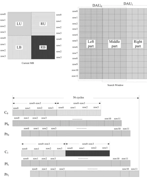
SAD4×4. The registers are used to delay the data input to fit the timing designed in Fig. 2-7, which is the timing diagram of level 0. The search window of the previous frame is divided into two parts, which are input to different DAUs. Thus, the image data can be reused more effectively, and selecting an MV takes only 56 cycles.
Fig. 2-7. The timing diagram of HMEA for level 0
2.3.2. Downsampling
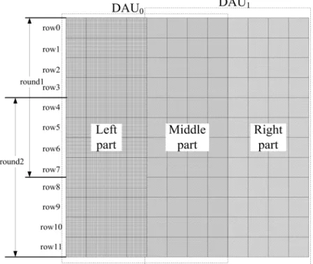
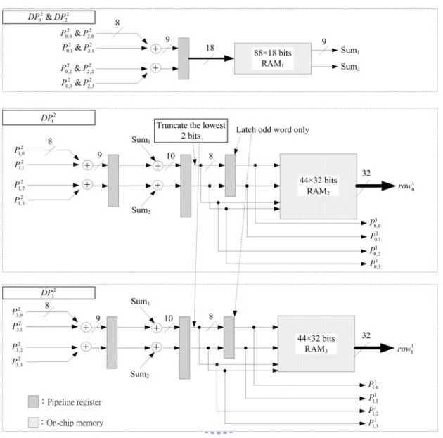
to down-sample an image is to input all of the image data to RAM, and then average four pixels as a single pixel. After numerous manipulations, an image that has one quarter of the original resolution is generated. This approach requires a large part of the available memory to store the original image, and this large amount of memory substantially increases the die size. A pipelined hardware is derived to downsample the images to fit the limitations on the memory and the die size. Figure 2-8 shows an
example of down sampling four rows of level 2, where l
j i
P, is the j-th pixel of the
i-th row, row , at level l, and Figs. 2-9 and 2-10 illustrate the pipelined il
down-sampling hardware for levels 2 and 1, respectively. l
k
DP , RAMi, and Sumk are
the data path of l
i
row , the on-chip memory of each DP, and the temporal summation
registers. In Fig. 2-8, four rows of level 2 are subsampled to get two rows of level 1 and one row of level 0 each loop, and a total of 72 loops are required for one CIF image. The procedure is described step by step as follows.