Piezoelectric-transducer-based optoelectronic
frequency synchronizer for control of pulse delay
in a femtosecond passively mode-locked
Ti:sapphire laser
Gong-Ru Lin, Yung-Cheng Chang, Tze-An Liu, and Ci-Ling Pan
We propose a piezoelectric transducer- 共PZT-兲 based optoelectronic frequency synchronizer to control simultaneously changes in the repetition rate, the relative pulse delay, and the phase noise of a passively mode-locked femtosecond Ti:sapphire laser with an intracavity saturable Bragg reflector absorber with respect to an electronic frequency reference. An optoelectronic phase-locked-loop-based PZT feedback controller with a proportional, integral, and differential共PID兲 circuit and a tunable voltage regulator is designed to achieve frequency synchronization, phase-noise suppression, and delay-time tuning. When the controlling voltage is tuned from⫺2.6 to 2.6 V, the maximum pulse-delay range, tuning slope, and tuning resolution of the laser pulse-train are 11.3 ns, 2.3 ps兾mV, and 1.2 ps, respectively. Setting the gain constant of the PID circuit at 10 or larger causes the delay-time tuning function to be linearly proportional to the controlling voltage. In the delay-time tuning mode the uncorrelated single-side-band phase-noise density of the frequency-synchronized laser is approximately⫺120 dBc兾Hz at an offset frequency of 5 kHz, which is only 7 dBc兾Hz higher than that of the electrical frequency reference. The proposed system also supports linear, continuous switching, and programmable control of the delay time of Ti:sapphire laser pulses when they are frequency synchronized to external reference clocks. © 2003 Optical Society of America
OCIS codes: 120.0120, 120.5050, 320.7160.
1. Introduction
Repetition rate, relative delay time, and phase-noise controls are the most important functions for syn-chronizing mode-locked Ti:sapphire lasers with elec-tronic frequency references. Control of the repetition rate and the phase noise of passively mode-locked Ti:sapphire lasers relies strictly on stabiliza-tion of the cavity length the or pulse-repetistabiliza-tion rate with respect to an ultralow phase-noise time base. To meet this demand, versatile feedback servo loops have been demonstrated for actively mode-locked Ti: sapphire lasers with frequency or phase tracked mode lockers1and for passively mode-locked
Ti:sap-phire lasers with slow saturable absorbers共for exam-ple, mixed of HITIC and IR140 dyes兲.2 Recent progress with phase-locked loops in stabilizing the relative timing jitters between actively mode-locked Ti:sapphire lasers has come close to including the subfemtosecond regime.2 However, control of the relative delay time between Ti:sapphire lasers and the electrical frequency reference is also important for applications such as free-space distribution of an optical clock, optical-time-division multiplexing com-munications, electro-optic sampling, and time-resolved spectroscopy. Typically, this control can be achieved by use of a reflection-type optomechanic de-lay line that externally adjusts the dede-lay time of a laser pulse train by tuning the optical path length. Unfortunately, the need for time-consuming align-ment and a bulky design disadvantages of such a true time-delay module that is meant to prevent the trans-verse shift in beam position that causes measuring distortions. To overcome these drawbacks, the at-tempts to control the pulse delay that is inherent in ultrafast lasers has aroused resurgent interest. Not long ago, a delay-time-tunable, actively mode-locked
The authors are with the Institute of Electro-Optic Engineering, National Chiao Tung University, 1001 Ta Hsueh Road, Hsinchu 300, Taiwan. G.-R. Lin’s email address is [email protected]. edu.tw.
Received 8 October 2002; revised manuscript received 15 Janu-ary 2003.
0003-6935兾03兾152843-06$15.00兾0 © 2003 Optical Society of America
Nd:YAG laser was demonstrated by phase shifting of the rf clock of a mode locker with an analog phase shifter.3 A similar concept was recently employed to control the relative delay time of the pulse train from two individual Ti:sapphire lasers.4 Most electrical pulse-delay schemes have been based on waveguide-type or voltage-controlled analog phase shifters with nonlinear共sinusoidal兲 function of the tuning voltage. To eliminate a nonlinear transfer function in an an-alog phase-shifting scheme, a modified phase-locked loop共PLL兲 technology has produced a digital and pro-grammable phase shifter.5 Subsequently, the new PLL phase shifter circuitry has been employed for in
situ delay-time control of gain-switched
semiconduc-tor6 and actively mode-locked fiber7 lasers. How-ever, such an inherent and programmable control of the delay time of passively mode-locked lasers has not yet been achieved with PLL phase shifters. Us-ing a passively mode-locked Ti:sapphire laser with a slow saturable Bragg reflector共SBR兲 absorber 共here-after referred to as a Ti:sapphire兾SBR laser兲 as an example, we describe an optoelectronic frequency synchronizer based on a piezoelectric transducer 共PZT兲 integrated with a digital PLL phase shifter circuit to implement both the inherent delay-time-tuning and phase-noise-suppressing functions. By feedback control of the cavity length by means of a PZT adhesive end mirror and addition of a voltage-controlled phase-delay circuit the stabilizer, charac-teristics such as maximum delay time, tuning resolution, and linearity; pulse width; and minimum single-sideband phase-noise density of delayed laser pulses from a Ti:sapphire SBR laser are measured.
A passively mode-locked Ti:sapphire SBR laser with a standard six-mirror X-folded cavity is shown in Fig. 1; it consists of a 5-mm-long Ti:sapphire rod, a pair of SF10 prisms for intracavity dispersion com-pensation, a SBR as the folded reflector, an output coupler with 95% reflectivity, and a PZT adhesive planar mirror共R ⬎ 99%兲 for active cavity stabiliza-tion. The laser was carefully aligned to prevent self-starting without a saturable absorber. We obtained the SBR by first growing a distributed Bragg reflector that comprised 15 pairs of 兾4-thick AlAs兾 Al0.25Ga0.75As layers periodically changed from high to low refractive index, and a兾2-thick Al0.25Ga0.75As top layer.8 Three strained InAlGaAs quantum wells with separated but sequential absorption peaks at
adjacent wavelengths were deposited to extend the absorption linewidth.2,9,10 The output power, pulse width, and repetition rate of the Ti:sapphire SBR laser at a pump power of 5 W共with an all-line large-frame argon-ion laser; Coherent Innova 400兲 are 250 mW, ⬍100 fs, and 85 MHz, respectively. The Ti: sapphire rod and the SBR were both temperature regulated for control of the residual thermal fluctua-tion below 0.1 °C. A SBR with a narrower gain win-dow provided a stronger pulse-shortening force to amplify the peak pulse and suppress random noise.2 Before an experiment, the uncorrelated phase-noise density of a free-running Ti:sapphire SBR laser is optimized by tuning of the intracavity gain band-width and the group-velocity density by an intracav-ity optical slot. Figure 2 illustrates schematically an active optoelectronic frequency synchronizer that consists of an optoelectronic PLL-based frequency synchronizer, a proportional, integral, and differen-tial共PID兲 controller,2and a tunable voltage regulator for simultaneous frequency synchronization, phase-noise suppression, and delay-time tuning. In the ex-periment the Ti:sapphire SBR laser is frequency synchronized to an ultralow-noise electrical fre-quency reference共Hewlett-Packard HP8662兲 by a fre-quency synchronizer. First, an optoelectronic harmonic mixer共OEHM兲 with a conversion loss 共de-fined as the power ratio of the microwave to the intermediate-frequency signal兲 of 35 dB is used to mix the harmonic component of repetitive optical pulses from the Ti:sapphire SBR laser with an ultralow-noise frequency reference. The homemade OEHM is in general a GaAs photoconductive switch, which consists of a microwave transmission line with an optoelectronic interaction gate. The operating principle of the OEHM is shown in Fig. 3. The ex-tension of discriminating frequency from fundamen-tal to higher harmonics facilitates better frequency and phase tracking with suppressed phase noise. In our case the 12th harmonic of the laser pulse train 共with a power of 10 mW兲 repeated at f0⫽ 82.342 MHz is mixed with the reference signal 共 fREF ⫽ 988.104 MHz, with a power of ⫺5 dBm兲 in the OEHM to generate an intermediate frequency 共IF兲 signal at
Fig. 1. Diagram of a typical passively mode-locked Ti:sapphire SBR laser: P1, P2, intracavity prism compensators; OC, optical
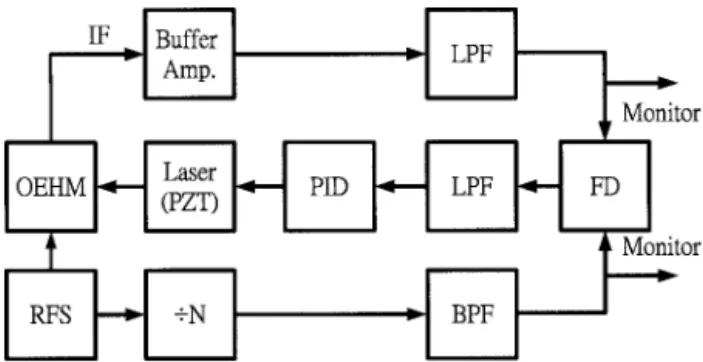
coupler. Fig. 2. Block diagram of a PZT-based optoelectronic stabilizer: ⫼N: frequency divider with divisor N; Buffer Amp., buffered am-plifier, BPF, bandpass filter; FD, frequency discriminator; LPF’s, low-pass filters; RFS, referenced frequency synthesizer; other ab-breviations defined in text.
fIF⫽ 321.6 kHz. The operation of the PLL at the IF band will benefit from a better signal-to-noise ratio than that at the base band because the cutoff fre-quency of the Ti:sapphire laser noise spectrum is⬃10 kHz. The IF signal was filtered, amplified, analog-to-digital converted, fed to a phase and frequency detector共Harris ICL8013 or Motorola MC4044兲, and then compared with the frequency-divided reference 共frequency prescaled from the HP8662 reference兲 to generate a feedback signal 共Verr兲. After passing through the PID circuit, signal Verrwas used to con-trol the PZT 共Physik Instrumente, P820.10兲. The 3-dB frequency bandwidths of the PID circuit and the PZT were determined as 4 and 7 kHz, respectively. Offsetting signal Verr with dc voltage共VREF兲 from a tunable voltage regulator11allowed the optical pulse train from the passively mode-locked Ti:sapphire SBR laser signal to be frequency synchronized but pulse-timing shifted with respect to the frequency reference. A high-speed photodetector共Antel AR-S2 with f3dB⫽ 18 GHz兲 in connection with a spectrum analyzer共HP 8560E; resolution bandwidth, 1 Hz兲 and a sampling oscilloscope 共HP54750A兲 was used to monitor the phase-noise spectrum and the relative delay time of the optical pulse train. The pulse width and the optical spectrum of the laser tuned to different delay times were monitored by an
autocor-relator and an optical spectrum analyzer, respec-tively. We further subtracted the fundamental from the 12th harmonic single-sideband共SSB兲 phase-noise spectrum to evaluate the relative timing jitter with-out the influence of intensity noise.12
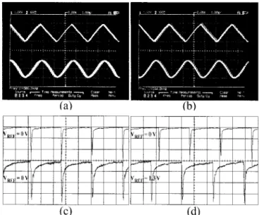
To characterize the performance of the PZT-based optoelectronic stabilizer in controlling the relative de-lay time between the laser pulse train and the refer-ence clock, we monitored the IF signals from the OEHM and the frequency-prescaled reference clock. It can be seen from Fig. 4共a兲 that the two signals are in phase without a controlling voltage共VREF⫽ 0 V兲. By setting VREF⫽ 2.6 V we observed the downcon-verted IF trace 共from the OEHM兲 to be nearly 180° out of phase with the reference clock; this corre-sponds to a leading shift in delay time of as much as 6.0 ns at a laser repetition frequency of 82.34 MHz, as shown in Fig. 4共b兲. Figures 4共c兲 and 4共d兲 further illustrate the measured shift in the real delay time of the optical Ti:sapphire SBR laser pulse train under different controlling voltages. In comparison with the upper trace, which defines the original pulse train, the lower trace in Fig. 4共c兲 reveals the in-phase laser pulse train at VREF⫽ 0 V, whereas the lower trace in Fig. 4共d兲 shows a leading pulse train with a relative delay time of⬃3 ns at VREF⫽ 1.3 V.
It was previously established that the gain con-stant of a phase detector is a decisive circuit param-eter in wide delay-time tuning with a PLL-based phase shifter. A digital phase frequency detector 共PFD兲 is thus more suitable for the proposed system owing to its relatively larger phase sensitivity共Kd⬵
1.141 V兾rad兲 and phase-sensing range 共PD ⫽ 4兲 than those of analog PFDs共with Kd⬵ 0.89 V兾rad and
PD⫽ 兲. We obtained the optimal circuit parame-ters by individually adjusting the gain and the
band-Fig. 3. Operating principle of the optoelectronic共OE兲 harmonic mixer illustrated in the frequency domain.
Fig. 4. Frequency-synchronized IF signals with共a兲 VREF⫽ 0 V
共lower trace, in phase兲 and 共b兲 VREF⫽ 2.6 V 共lower trace兲, compared
with those of the reference clock共upper trace, out of phase兲. The relative shifts in delay time of the laser pulse train共c兲 with VREF⫽
0 V 共lower trace兲 and 共d兲 with VREF ⫽ 1.3 V 共lower trace兲 are
width of the PID loop filter. The larger gain of the PID circuit, although it helps to suppress phase noise beyond the PID bandwidth, however, has restricted the scanning rate of the delay-time controlling pro-cess. Furthermore, the delay-time tuning function is in approximately linear proportion to VREF only when the gain constant of the PID circuit is below 0.01, as shown in Fig. 5. That is, the largest and most stable delay-time tuning can be achieved in this case. As the gain constant increases to 0.1 or larger, the transfer function of the proposed system becomes nonlinear and varies with the shrinkage of the max-imum delay-time tuning range. In addition, a satu-ration effect of the PID circuit that shrinks the delay-time tuning range becomes more pronounced as the gain constant of the PID circuit increases to 10 or larger. The relative delay time and repetition rate of the laser pulse train with respect to the microwave reference clock can be plotted as a function of con-trolling voltage by use of a lock-in detection tech-nique. As shown in Fig. 6, the maximum delaying
time is 11.3 ns for a tuning responsivity of 2.3 ns兾V. However, the frequency-discriminating共or tracking兲 process can no longer be sustained as VREFexceeds the limits共⫺2.6 V ⬍ VREF⬍ 2.6 V兲, which inevitably randomizes the repetition frequency, phase, and de-lay time of a laser pulse train with respect to a mi-crowave clock.
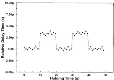
The accuracy and stability of delay-time tuning of a laser pulse train is characterized by a switching and holding test, as shown in Fig. 7. The switching pe-riod and the duty cycle are set as 20 s and 50%, respectively. Faster switching speeds of as much as 10 ms can be achieved but are, however, beyond the measuring limitations of lock-in detection. We ob-served that the phase-switching error of an optoelec-tronic PLL-type frequency synchronizer is ⬃0.1°, which is limited by the short-term drift in output voltage of a thermally stabilized high-precision reg-ulator共National Semiconductors LM399 with a drift-ing slope of 3.4 ⫻ 10⫺3°兾min兲. Such a switching error corresponds to a change in delay time of⬃1.2 ps. It is worth noting that a smaller tuning respon-sivity is required for obtaining a subpicosecond tun-ing resolution as small as 0.1 ps. Although this can resolution be achieved by use of a digital phase de-tector and a PID circuit that permits a larger input of controlling voltages共for example, VREFcan be at least ⫾26 V兲, increasing the repetition rate of a Ti:sapphire laser by shortening its cavity length is an alternative approach.
In addition, the repetition frequency共 frep兲 and the double-sided band spectrum of the laser operated at various values of VREFwere monitored by a spectrum analyzer with a resolution bandwidth of 1 Hz. For example, it is shown in Fig. 8 that frep remains in-variant when VREFvaries from⫺1.3 to 1.3 V. Pre-cise measurement of the repetition rate with a microwave frequency counter further confirms the frequency-discriminating stability of the PZT-controlled frequency synchronizer within ⫾0.1 Hz. By measuring the 12th harmonic components of the laser pulse train 共 f ⬵ 0.98 GHz兲 with an average
Fig. 5. Relative delay time of the passively mode-locked Ti:sap-phire SBR laser pulse train as a function of controlling voltage 共VREF兲 measured at several gain constants of a PID circuit.
Fig. 6. Relative delay time共solid curve兲 and repetition rate 共dot-ted curve兲 of the passively mode-locked Ti:sapphire SBR laser pulse train as a function of controlling voltage.
Fig. 7. Short-term switching and holding test for delay-time tun-ing of the passively mode-locked Ti:sapphire SBR laser pulse train.
photocurrent and a detected power level of 1 mA and ⬎⫺25 dBm, respectively, we characterized the SSB phase-noise spectrum of the laser. Both correlated 共with offset frequency foff⬍ 500 Hz兲 and uncorrelated 共 foff⬎ 500 Hz兲 phase-noise density of the Ti:sapphire SBR laser in controlling mode can be further reduced by 10 dB or more. We observed that the phase noise of the Ti:sapphire SBR laser reached the noise floor of the measurement apparatus共⫺120-dBc兾Hz at an off-set frequency of 5 kHz兲. The inverse frequency de-pendency 共a 1兾f4 relationship兲 below 1 kHz of the measured phase-noise spectra is also in good agree-ment with theoretical predictions.2,11,12 We should also address the contribution of the OEHM to the PZT-based frequency synchronizer that permits the selection of much higher harmonics of the laser at relatively low intensity noise owing to its restricted AM–PM conversion and microwave biasing regime. Note that no significant degradation in noise perfor-mance of the laser during delay-time tuning was
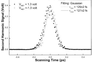
found. The nearly unchanged SSB phase-noise spectra that result from tuning VREFfrom 1.3 to⫺1.3 V at a switching rate ofⱖ1 Hz兲 are shown in Fig. 9. Furthermore, the autocorrelated traces of the Ti:sap-phire SBR laser pulses controlled at various values of
VREFare nearly identical to their FWHM of approx-imately 127–129 fs, as shown in Fig. 10. The stabi-lizer enjoys the advantages of a linear voltage-tuning function and programmable control not found in other circuitry.13,14 The present scheme is also suit-able for relative delay-time tuning of two individual mode-locked Ti:sapphire lasers.
In conclusion, we have demonstrated a novel PZT-controlled frequency synchronizer to implement a delay-time tunable, passively mode-locked Ti:sap-phire saturable Bragg reflector laser. An optoelec-tronic phase-locked-loop-based PZT feedback controller with a proportional, integral, and differen-tial controller and a tunable voltage regulator was designed to achieve simultaneously frequency syn-chronization, phase-noise suppression, and delay-time tuning. Adjusting the controlling voltage from ⫺2.6 to 2.6 V provides optimal performance of the synchronizer in continuous delay-time tuning with maximum delay range, tuning responsivity, and tun-ing resolution of 11.3 ns, 2.3 ps兾mV, and 1.2 ps, re-spectively. The delay-time tuning function is linearly proportional to the controlling voltage when the gain constant of the PID circuit is set at 10 or larger. Our system facilitates linear, continuous, switching, and programmable control of delay times of Ti:sapphire laser pulses when it is frequency syn-chronized to external reference clocks. In feedback control mode, the pulse width, the repetition rate, and the single-sideband phase noise of a Ti:sapphire SBR laser remained invariant during delay-time tun-ing or switchtun-ing. Synchronization and relative delay-time tuning between two mode-locked Ti:Sap-phire lasers by use of the proposed scheme is straight-forward.
This research was supported in part by the Na-tional Science Council of the Republic of China under
Fig. 9. SSB phase-noise density spectra of the 12th harmonic of the passively mode-locked Ti:sapphire SBR laser pulse train mon-itored at two controlling voltages.
Fig. 10. Autocorrelated traces of passively mode-locked Ti:sap-phire SBR laser pulses monitored at two controlling voltages. Fig. 8. Radio frequency spectra measured by monitoring of the
optoelectronic-converted signal from the passively mode-locked Ti: sapphire SBR laser pulse train with its delay-time switching for two values of VREF: RBW, resolution bandwidth; CF, center
grants NSC90-2215-E-027-008 and NSC91-2215-E-009-039.
References
1. R. K. Shelton, S. M. Foreman, L.-S. Ma, J. L. Hall, H. C. Kapteyn, M. M. Murnane, M. Notcutt, and J. Ye, “Subfemto-second timing jitter between two independent, actively syn-chronized, mode-locked lasers,” Opt. Lett. 27, 312–314共2002兲. 2. J.-M. Shieh, S.-C. Liu, and C.-L. Pan, “Characterization and reduction of phase noise in passively mode-locked Ti:sapphire lasers with intracavity saturable absorbers,” J. Opt. Soc. Am. B 15, 1802–1806共1998兲.
3. C. K. Johnson and J. Qian, “Picosecond laser timing by rf phase shifting,” Rev. Sci. Instrum. 61, 1158 –1160共1990兲.
4. L.-S. Ma, R. K. Shelton, H. C. Kapteyn, M. M. Murnane, and J. Ye, “Sub-10-femtosecond active synchronization of two pas-sively mode-locked Ti:sapphire laser oscillators,” Phys. Rev. A
64, 021802共2001兲.
5. G.-R. Lin, T.-S. Hwang, Y.-H. Chuang, S.-C. Wang, and C.-L. Pan, “Broad-band共ⱖ20 GHz兲 laser-diode-based optoelectronic microwave phase shifter,” IEEE Trans. Microwave Theory Tech. 46, 1419 –1426共1998兲.
6. G.-R. Lin, “Optoelectronic delay-time controller for laser puls-es,” Opt. Lett. 25, 799 – 801共2000兲.
7. G.-R. Lin and Y.-L. Cheng, “Tuning the delay-time of harmon-ically mode-locked erbium-doped fiber laser pulses by a
frequency-discriminated phase shifter,” Microwave Opt. Tech-nol. Lett. 30, 168 –170共2001兲.
8. J.-M. Shieh, T.-C. Huang, K.-F. Huang, C.-L. Wang, and C.-L. Pan, “Broadly tunable self-starting passively mode-locked Ti:sapphire laser with a triple-strained quantum-well saturable Bragg reflector,” Opt. Commun. 156, 53–57共1998兲. 9. S. Tsuda, W. H. Knox, S. T. Cundiff, W. Y. Jan, and J. E. Cunningham, “Mode-locking ultrafast solid-state lasers with saturable Bragg reflectors,” IEEE J. Sel. Top. Quantum Elec-tron. 2, 454 – 464共1996兲.
10. M. J. Hayduk, S. T. Johns, M. F. Krol, C. R. Pollock, and R. P. Leavitt, “Self-starting passively mode-locked tunable femto-second Cr4⫹:YAG laser using a saturable absorber mirror,” Opt. Commun. 137, 55–58共1997兲.
11. D. E. Spence, J. M. Dudley, K. Lamb, W. E. Sleat, and W. Sibbett, “Nearly quantum-limited timing jitter in a self-mode-locked Ti:sapphire laser,” Opt. Lett. 19, 481– 483共1994兲. 12. H. A. Haus and A. Mecozzi, “Noise of mode-locked lasers,” J.
Quantum Electron. 29, 983–996共1993兲.
13. G.-R. Lin and Y.-C. Chang, “Demonstration and optimization of an optoelectronic phase-locked phase shifter for optical mi-crowave signals,” IEEE Photon. Technol. Lett. 12, 1555–1557 共2000兲.
14. D. Von der Linde, “Characterization of the noise in continu-ously operating mode-locked lasers,” Appl. Phys. B 39, 201– 217共1986兲.
![[2015-Fall] WNFA lab1 - CamCom](data:image/gif;base64,R0lGODlhAQABAIAAAP///wAAACH5BAEAAAAALAAAAAABAAEAAAICRAEAOw==)