Damping
of
subsynchronous oscillations using
adaptive controllers tuned by artificial neutral
networks
Y.-Y. HSU, PhD L.-H. Jeng, MSc
Indexino terms: Subsynchronous resonance. Static V A R comaensator. Power system stabiliser, Arr@cial neural network, Optimal control, Back propagation
Abstract: Artificial neural networks (ANNs) are utilised to adapt the controller gains of two widely used control schemes i.e. static VAR compensators (SVC) and excitation controllers (EC), for the damping of subsynchronous resonance (SSR) on a power system. To have good damping character- istics of SSR modes over a wide range of oper- ating conditions, the parameters of the adaptive controllers are adapted based on generator loading conditions. Multilayer feedforward artifi- cial neural networks (ANNs) are developed to serve for the purpose of controller parameter adaptation. The inputs to the ANN include the real power output P and reactive power output Q which characterise generator loading conditions. The outputs from the ANN are the desired con- troller gains. Time domain simulations are also performed on the IEEE first benchmark model to demonstrate the effectiveness of the proposed adaptive control schemes.
List of symbols general
A , B, C = system matrix
Q,
R , S = performance index of optimal control H(s), H,(s), H J s ) = transfer function of the compensator 0, w = rotor angle and rotor speedb = generator torque angle
v,
1 = voltage and currentR , X = resistance and reactance
BL., Bc = susceptances of the inductor and
T = torque
V R = voltage regulator output a = actuator signal 9 = governor opening e, = capacitor voltage M K = spring constant L T = transformer inductance capacitor
= per unit output voltage of exciter
= moment of inertia (M = 2 H )
~ -~
C IEE, 1995
Paper 198W (P9), received 13th October 1994
The authors are with the Department or Electrical Engineering, Na- tional Taiwan University, Taipei, Taiwan, Republic of China I E E Proc.-Gener. Transm. Distrib., Vol. 142, No. 4, July 1995
*E = compensator current e, = compensator voltage 'T = transmission line current subscripts
d, 4
F = field circuit D ,
Q,
SH P = high pressure turbine
I F = medium pressure turbine
LPA, L P B = low pressure turbine
E X = exciter
PrefX
= d-axis and q-axis stator quantities
= damper windings
A = linearised quantities
1 Introduction
Series capacitors have been placed on transmission lines to enhance transmission capability by partially compens- ating line reactance. These series capacitors, coupled with line reactance, will introduce an oscillation mode which may interact with one of the torsional modes inherent in the mass spring system, resulting in subsynchronous reso- nance (SSR) [I-31. To prevent generator shaft damages caused by undamped subsynchronous oscillations, various countermeasures to the SSR problem such as excitation controllers [4-61 and thyristor controlled static VAR compensators [7-91 have been proposed. In a previous work conducted by the authors [9], a pro- portional integral derivative (PID) static VAR controller was designed to improve the damping characteristics of the SSR modes. It is concluded from the results that sub- synchronous oscillations could be effectively damped by the proposed PID static VAR controller. The controller gain was designed based on a nominal operating condi- tion and remained fixed no matter how the generator operating conditions changed. In daily operations, the operating point of a generator will drift over a wide range owing to random load changes or unpredictable disturbances such as a fault in the system. To keep the same damping effect under different loading conditions, it is desirable to adapt the controllers gains in real time. In the literature, adaptive controllers or self-tuning control- lers for both SVC and PSS have been proposed for the
Financial support given to this work by the National Science Council of ROC under contract number NSC82-0404-E002-72 is appreciated.
damping of low frequency electromechanical modes [lo- 121. In these self-tuning controllers, the system param- eters are identified using on-line measurements and a proper set of controller gains are then determined in real- time based on the identified system model. A major dis- advantage with this approach is that system identification and gain determination require much com- putational effort in real time. To overcome this difficulty, artificial neural networks (ANNs) [13], which have found several interesting applications in power systems [14, 151, have been employed to tune the parameters of power system stabilisers without the laborious work of system identification [16]. In a recent work [17], the eigenvalues for the SSR modes were estimated by the artificial neural network approach. In general, an artificial neural network is a highly distributed, parallel computation machine which can be used to perform complicated non- linear mappings between its inputs and outputs in a very short period. Therefore, we propose to adapt the control- ler gains of the static VAR compensator and excitation controller in real-time by using the artificial neural network in this work, To demonstrate the effectiveness of the proposed ANN based adaptive control scheme, various controllers, including adaptive SVC, adaptive EC, fixed gain SVC, fixed gain EC, optimal SVC, and optimal EC, are designed for the IEEE first benchmark model [18], and then, time domain simulations are per- formed for systems equipped with these control schemes individually, for the purpose of comparison. It is con- cluded from the results in this work that the unstable SSR modes can be effectively damped by the proposed adaptive controller over a wide range of operating condi- tions.
2 System model
The IEEE first benchmark model with series capacitor compensated transmission line as shown in Fig. 1 is
Vt
Fig. 1 IEEEJirst benchmark model with static V A R compensator
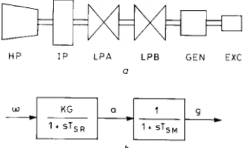
employed as the test system of this work. To provide damping effect for the SSR modes on this system, the SVC and EC are utilised as countermeasures. The static VAR compensator comprising a fixed capacitor and a variable inductor is connected through a step-down transformer to the generator bus. The block diagrams of the mass spring system and speed governor system is shown in Fig. 2.
Fig. 3 depicts the block diagram of the static VAR compensator with its controller. Note that the suscept- ance of the inductor E , can be regulated by adjusting the firing angles of thyristors THI and TH2 according to the variations in terminal voltage
v.
The output signal U ofthe controller is shown in this Figure. The block dia- 416
grams of the static excitation system and the adaptive excitation controller are shown in Fig. 4.
Basically, both the SVC controller and excitation con- troller are PID controllers with generator speed devi- ation Am and current deviation AI as their inputs. To
U H P I P L P A LPE G E N EXC a b Fig. 2 system
a Mass spring system b governor
Block diagrams of mass spring system and speed gouernor
Fig. 3
"ret
VPSS _ f
SVC controller
Block diagram of static VAR compensator with SVC controller
power system stabiliser Fig. 4
tion controller
Block diagram of static excitation system and adaptive excita-
keep good damping effects under disturbance conditions, the controller gains K,,, K , , , K,,, K,,, Kim, and K,,, which are fixed at certain values all the time in a fixed- gain controller, are adapted in real-time by the ANN based on on-line measured generator operating condi- tions.
In this work, the generator is represented by
D-Q
axis equivalent circuits [l, 21. The model and parameters of the SVC are taken from Reference 4. All system data used in this paper are listed in Appendix 9.1.7 0 0 -
0
x
3
3.1 SVC controller design
In the design of a PID SVC controller, the nonlinear system equations of the study system are linearised around a nominal operating condition first, and the pole placement method in modal control theory [19] is then applied to determine a proper set of controller param- eters T,,, T,,, K,,, K,,, K,,, K,,, and K,,, such that all SSR modes can be effectively damped. The linearised nonlinear equations are of the following form:
Design of a fixed gain controller
X = A X ( t )
+
BU(t) (1)Y =
cx(t)
(2)X = CwH, O N , W, , @r w A , @ A 1 w B , 08, W, 6, w x , where
8 X ? a, g, T H , T A ,
q ?
ecd 9 1 e B d , e B q ,i F , i,, i,, i Q , is, i T d ,
k,,
i s d , i B q , B L ,%I'
is the state vector,
u(t)
is the input vector andY = [AwA1lT (3)
is the output vector.
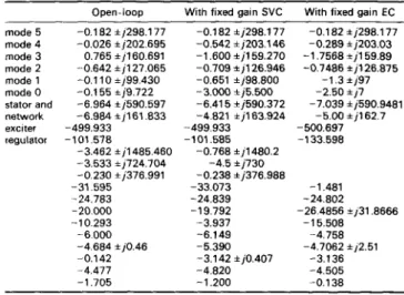
Then, the eigenvalues of the system without controller can be computed and are summarised in the second column of Table 1.
From the second column of Table 1, mode 3 is negat- ively damped while mode 4 is poorly damped. To improve the dampings of the SSR modes, an effective controller is needed. mode S V C , AsVC- 1 8 0 - 1 6 0 - mode 3 , Aa++ 1 4 0 -
-
6 5 0 - CnE
600 - 550L
.morle,o,hq
'P ' , - 5 0 - 4 5 - 4 0 - 3 5 - 3 0 -10 - 0 5 0 0 5 1 0real part real part
Fig. 5 Root loci of the open-loop system
of the root loci reveals that the modes which are most sensitive to the drifts in loading conditions are the two torsional modes 1, and A,, and SVC mode. As a result, we can prespecify the six eigenvalues for the three modes as follows:
- 3.0
k
j7.5 - 1.6 j159.27 -4.5 j730Table 1 : System eigenvalues a t P = 0.9, 0 = 0.435. V = 1.05, XJX, = 0.5
Open-loop With fixed gain SVC With fixed gain EC mode 5 mode 3 mode 2 mode 1 mode 0 stator and network exciter regulator mode 4 -0.1 82 i j298.177 -0.026 i j202.695 0.765 ij160.691 -0.642 ijl27.065 -0.1 10
*
j99.430 -0.1 55 ij9.722 -6.964 ij590.597 -6.984 ij161.833 -499.933 -101,578 -3.462 i jl485.460 -3.533 ij724.704 -0.230 +j376.991 -31.595 -24.783 -20.000 -10.293 -6.000 -4.684 ij0.46 -0.142 -4.477 -1.705 -0.1 82 *j298.177 -0.542 ij203.146 -1.600 i jl59.270 -0.709*
j126.946 -0.651 ij98.800 -3.000 ij5.500 -6.41 5 ij590.372 -4.821 i j163.924 -499.933 -101.585 -0.768 +j1480.2 -4.5 ij730 -0.238 ij376.988 -33.073 -24.839 -1 9.792 -3.937 -6.149 -5.390 -3.142 ij0.407 -4.820 -1.200 -0.182 ij298.177 -0.289 5 j203.03 -1.7568 ij159.89 -0.7486 +j126.875 -1.3ki97 -2.50 *)7 -5.00 i i162.7 -7.039 ij590.9481 -500.697 -1 33.598 -1.481 -24.802 -1 5.508 -4.758 -4.7062 ij2.51 -3.136 -4.505 -0.138 -26.4856 ij31.8666The controller gains can be determined as K p m = 72.293 K,, -26.48 K D m = 1.93428 K,, = 0.155 K,, = 3.835 KD, = -0.000453
under the operating condition of P = 0.9 and Q = 0.435. Column 3 of Table 1 lists the eigenvalues for the system equipped with the SVC and its controller. It is observed that the torsional oscillations are suppressed satisfactorily.
3.2 Excitation controller design
Using the same procedures as mentioned above, the parameters of a PID EC can be determined to improve the damping of SSR modes.
The assigned poles are as follows: - 2.5 j5.0
1.2 f j97.1 1.76 k j l 6 3 . 3 The controller gains are
Tw, = 0.02 s K p m = 486.171 K,= = -331.453 K,, = 3.2142 T,, = 0.23 s K,, = 2.39 K,, = 10.876 K D , = -0.004
The eigenvalues of the system with this excitation con- troller are listed in Column 4 of Table 1.
4
4.1 Artificial neural network
The multilayer feedforward artificial neural network as shown in Fig. 6 will be used in this work to adapt con- troller gains of both the PID SVC and PID EC in real time. Before the ANN can be used to adapt the controller gains in real time, it is necessary to determine a proper set of values for the connection weights
wj.
The process of reaching the connection weights is normally carried out off-line and is usually referred to as the training process. In the training process, we first compile a set of training patterns and store these training patterns in the training set. Each training pattern comprises a set of input data and the corresponding output data. In the present work, generator real power output P and reactive power output Q, which can be used to characterise gener- ator loading conditions, are selected as the inputs to the ANN. For a generator which is operated at the specified values of P and Q, we can proceed to determine a set of PID controller gains ( K P , , K , , , K,,, K,,, K,, and K , , ) using the pole placement method, and the results are treated as the ANN'S output.418
Application of the ANN t o adapt controller gains
4.2 Application of the ANN to adapt PID controller gains
As mentioned in the previous Section, for the system equipped with SVC, the three modes A,, I , and A,,, are most sensitive to the drifts in operating points. Therefore,
network o u t p u t
connection we ghts
,
neuron outputI
lnetwork InputP O
Fig. 6 Multilayer feedforward art$cial neural network
on creating training patterns for training the ANN used on tuning SVC controller, these three modes are re- assigned as follows:
- 3.0
k
j7.5 - 1.6 & j159.27 -4.5 f j730On the other hand, for the system with only excitation controller, the three modes I,, I,,,,,, and I , are most sensitive to the drifts in operating points. The assigned poles are now selected as:
- 2.5
k
j7.0 - 1.3 ,j97.0 -5.0i
j162.7After assigned poles of these two systems have been determined, the following process can be employed for training pattern creation and neural network training for both controllers.
For every possible conbination of P and Q within the interesting range of (0.6
<
P<
1.5, -0.4<
Q<
1.01, we can compute a set of desired controller gains. Each gener- ator operating point and the corresponding PID controi- ler gains constitute a training pattern. These training patterns are stored in the training pattern set for the purpose of determining the connection weights.A training pattern set comprising 450 training pat- terns, which cover a wide range of operating conditions, is finally used to train the desired ANN. It should be noted that we use two hidden layers with ten hidden nodes per layer in the present work. The momentum con- stant CI is fixed at 0.9 and an adaptive learning rate as described in Reference 17 is employed.
5 Optimal control schemes
The optimal linear state feedback technique is well docu- mented in the literature [2, 203. The technique is also applied to design the controllers for both SVC and PSS in this work for the purpose of comparison.
For the linear system (eqn. l), the control u(t) which minimises the performance index
J = [ ( x r Q x
+
urRu) dr (4)is given by the feedback control law in terms of system states as
u(t) = - R - ' B r S ( t ) X ( t ) ( 5 )
0 = ATS(t)
+
S ( t ) A ~ S(r)BR-'B'S(t) ( 6 )where S ( t ) is the solution of the matrix Riccati equation
The set of nonlinear eqns. 6 can be solved for S(t) in closed form.
It should be noted that the matrix Q is in diagonal form in this study and its elements corresponding to the states of the test system itself are the same in both excita- tion controller design and SVC controller design.
6 Simulation results
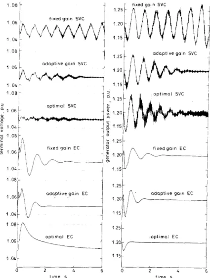
To demonstrate the effectiveness of the proposed adapt- ive controller, time domain simulations are performed on the IEEE first benchmark model as described in Section 2. A 0.1 pu step input in mechanical torque AT, lasting for four cycles is employed as the disturbance. Fig. 7
1 03
I
I 0 2 4 6 t e r m i n a l voltage 1 0 - 1 0 - :09 0 8 I 0 7 ' J 0 2 4 6 g e n e r a t o r out p u t power Fig. 7 Q = 0.435Dynamic responses ofgenerotor without any controller P = 0.9.
illustrates the response curves of the system without con- troller under the operating condition considered in Section 3. The system is unstable, just as we predicted in Section 3 based on the negatively damped eigenvalues in the second column of Table I .
Three different design techniques explained previously are applied to design both the excitation controller and the controller of static VAR compensator. Time domain simulations of the test system equipped with six different control strategies are performed on three loading condi- tions of, generator, i.e. P = 0.9, p j = 0.9 lagging (OPTl),
P = 0.7, p f = 0.75 lagging (OPT2), and
P
= 1.2, pf= 0.75 lagging (OPT3). for comparing the damping effect of each control scheme. The test results are summarised in TableL.
At OPTl (Fig. 8), since all controllers are designed a t this operating condition, it is observed that all control schemes provide good dampings for the SSR modes at this operating point.
At OPT2 the generator is working at a light loading condition. From Fig. 9, the Optimal SVC cannot main- tain stable system operation, but the fixed gain SVC and adaptive gain SVC still work well. As for the excitation control, the optimal PSS have the best damping effect on SSR modes, but its voltage deviation is also the largest. Besides, the ANN tuned adaptive excitation controller can provide much better damping for SSR modes than the fixed gain excitation controller.
At OPT3 (Fig. 10) the generator is working for a heavy load. Both the system with a n optimal SVC and the system with a fixed gain PID SVC are unstable, while the ANN tuned adaptive SVC can keep the system in stable operation. But, for excitation controllers, the response characteristic is similar to that a t OPT2, but the voltage deviation of the optimal excitation controller is larger.
7 Conclusions
A novel tuning technique based on ANN is proposed to adapt the PID controller gains of both SVC and PSS to control the subsynchronous resonances on capacitor compensated transmission lines. The ANN is trained with a set of training patterns in the training set. Each training pattern includes two portions; one is the inputs of the ANN which contain the operating condition data of generator ( P and Q) and the other is the outputs of ANN which contain the desired controller gains under the particular operating point. Generalised delta rule with a n adaptive momentum constant is adopted during the training process.
Once trained, the ANN is capable of adapting the P I D controller gains in real-time based on on-line measured system operating condition. From the time simulation results, it is concluded that, with the controller gains adapted by the ANN, the static VAR compensator can
Table 2: Summary of test results
Control scheme Static VAR compensator Excitation control controller type fixed-gain adaptive state feed- fixed-gain adaptive state feed-
PID PID tuned back optimal PID PID tuned back optimal by ANN control by ANN control
P = 0.9, pf = 0.9 lagging stable stable stable stable stable stable
P = 0.7, pf = 0.75 lagging stable stable unstable poor stable stable
P = 1.2. pf = 0.75 lagging unstable stable unstable stable stable stable (OPT1. Fig. 8)
(OPTZ. Fig. 9) damping
(OPT3. Fig. 10)
419 I E E Proc-Gene?. Transm. Distrib., Vol. 142. N o . 4, J u l y IYY5
, /- 0 P 3 o_ n m ._._I-- 0 W 0 L 0 VI m ~L 0 0, in
generator output power, p u
0 0 0 0 0 CO LD VI 0 (D 0 0 0 0 0 m (0 m ID Ln 0 VI 0 0) W cn 0 0 0 a
x
< m 10 3 VI < 0 n 2 0 m t e r m i n a l v o l t a g e p u a 4 a 2 2 h m O : 0 0 m 0 c 2 0 c 2 0 m 0 N-
3 m VI c m 0 N * 3 VI c m 0 c l 0 P < m 10 0 0 '0, 3e
n -. mprovide better damping characteristics for sub- It takes a very short period for the ANN to reach the synchronous oscillations over a wide range of operating desired controller gains based on the measured P and Q. conditions than both the fixed gain controller and the This makes the ANN approach very attractive for the optimal controller. While both the classical fixed gain purpose of gain adaptation. Although the training controller and the optimal controller may fail in some process takes time, this will not cause any disadvantage
1 O S k a d a p t i v e g a i n SVC I a d a p t i v e gain SVC
i
1 1 5 o p t i m a l SVC optimal SVC oi fixed goln EC m 1 1 51
‘
a d a p t i v e g a i n E C a d o p t i v e gain E CI
: