Active feedback microstrip leaky wave
antenna-synthesiser design with suppressed
back lobe radiation
Ying-Chou Shih, Shing-Kwang Chen, Cheng-Chi
Hu
and C.F. Jou
The design of an active leaky-wave antenna which integrates the antenna with a feedback synthesiser is introduced The measurement result shows that the antenna has very low back lobe radiation compared with that of traditional single- feeding leaky-wave antennas. Single frequency shows that the radiated power difference between
and back lobe is > 15dB at 8.2GHz. For the designed feedback synthesiser antenna, the measured radiated power difference between the main beam and back lobe is > 15dB at 9.25GHz, and the scanning angle is -5" as the synthesiser frequency sweeps from
9.25 to 9.37GHz.
Introduction: Active antennas have the advantages of small size, simple structure, and ease of fabrication, and allow for the incor- poration of more functions within the same substrate. Active leaky-wave antennas have also
been
intensively investigated in [I, 21. Although the active leaky-wave antenna has many advantages, the large reflected back lobe radiation caused by the open-ended structure can be problematical. In [3], it was mentioned that with a strip of 10.0cm (2.23&), the leaky-wave antenna can radiate -65% of the power,with
the remaining 35% being largely reflected from the open end producing a large back lobe at the same angle from broadside. However, it was proposed in 131, that if the antenna strip length is increased to 21.7cm (4.85&), 90% of the power can be radiated. In this Letter, an alternative method is introduced to suppress back lobe radiation. An active leaky-wave antenna integrated with a feedback ampwier and with a feedback synthesiser is demonstrated. With an antenna length of -9cm (2.46b), the back lobe radiation level can be suppressed to 15dB below the main beam. Measurement results for both of these two types of circuits show that the back lobe of the leaky-wave antenna is effectively suppressed.amplifier
bandpass filter
-tapei leaky-wave antenna (scm)
antenna second stage amplifier
passive loop filter
vco
b
/52yli
Fig. 1 Configurations of integrated active leaky-wave antenna with feed- back amplifier and integrated active leaky-wave antenna with feedback synthesiser
a Configuration with feedback amplifier b Configuration with feedback synthesiser
Design and measurement results:
(i) Active leaky-wave antenna with feedback amplifer structure: Fig. l a shows the active leaky-wave antenna with a feedback amplifier structure. The circuit consists of three parts: amplifier, bandpass filter, and leaky-wave antenna. The entire circuit is fabricated on RTDuroid substrate with a dielectric constant of 2.2 and thick- ness of 20mils. Fig. 2 shows the power dissipation of the micros-
trip leaky-wave antenna. From the result of Fig. 2 and [4], we know that the first high order mode is successfully excited by
asymmetrical feeding. The taper is added behind the end of the antenna to reduce the discontinuities which could cause reflected waves and the generation of undesired modes. This antenna with a taper has a transmission loss of 9.2dB (due to the radiation of the leaky-wave antenna), and it is placed in the path of the ampwier feedback loop. An NEC42484 low noise HEMT is used as the
amplifier, and the drain is biased at 2.0V with a drain current of
1OmA. m e amplifier with bandpass filter can provide -10dB small-signal gain within the bandwidth (centred: 8.2GHz, span: SOOMHz ). The amplifier is placed in the loop in order to satisfy the gain requirements for oscillation. To satisfy the Barkhausen criterion, the electrical length of the feedback loop is adjusted to be a multiple of 360". The active antenna is designed to oscillate
... ... ...
- I O 1
6
A
l bfrequency,GHz
Fig. 2 Measured power dissipation of leaky-wave antenna
-351 , , , ,
,
, , II
a I 9 e4 -5{ -30 w s g b 1525/3Fig. 3 H-plane pattern measurements of integrated active leaky-wave antenna with feedback amplifier and with feedback synthesiser a H-plane pattern measurements with feedback amplifier b H lane pattern measurements with feedback synthesiser
-
-&
- f = 9.25621 GHz513
ELECTRONICS LETTERS
1st April 1999 Vol. 35No.
7at a frequency of 8.2GHz. Fig. 3a shows the radiation patterns of the H-plane. The power between the main beam and back lobe is > 15dB and the effective isotropic radiated power (EIRP) is 19.5 dBm.
(ii) Active leaky-wave antenna with synthesiser structure: Fig. lb shows the active leaky-wave antenna with a synthesiser structure. The circuit consists three parts: synthesiser, amplifier, and leaky- wave antenna. Two NEC42484 low noise HEMTs are used as the fist and second stage amplifiers, respectively, the drain is biased at 2.0V with a drain current is 10mA. The synthesiser is composed of a VCO, a synthesiser IC and a passive loop filter. The synthe- siser itself has -300MHz operation bandwidth, from 9.1 to 9.4GHz. When the circuit forms a closed loop with the feedback synthesiser and the leaky-wave antenna, in the closed loop the active antenna scanning frequency is 9.25-9.37GHz. Fig. 3b shows the radiation patterns of the H-plane at 9.25GHz. The power dif- ference between the main beam and back lobe is > 15dB. The scanning angle is -5" as the frequency is swept from 9.25 to 9.37GHz.
Conclusion: In this Letter, by using a 'taper-end feedback struc-
ture we have successfully demonstrated a method which can effec- tively reduce the back lobe radiation of a leaky-wave antenna without increasing the strip length of the antenna. This active leaky-wave antenna has the advantages of a narrow main beam and very low back lobe radiation level, with a shorter antenna length. Such an active integrated antenna is suitable for power combining applications and active antenna arrays for communica- tions and radar systems.
Acknowledgment: This work was supported by the National Science Council under grant NSC88-2213-E-009-099.
0 IEE 1999
Electroncis Letters Online No: 19990410 DOI: IO. 1049/el:I 9990410
Ying-Chou Shih, Shing-Kwang Chen, Cheng-Chi Hu and C.F. Jou (Institute of Communication Engineering, National Chiao Tung
University, Hsinchu, Taiwan, Republic of China)
18 February 1999
References
1 CHOU, G.-I., and TZUANG, c.-K.: 'Oscillator-type active-integrated antenna: The leaky-mode approach, IEEE Trans., 1996, MTT-44, CHENG-CHI HU, , JIN-JEI wu, , and JOU, c.F.: 'An active frequency-
tuned bean scanning leaky-wave antenna', Microw. Opt. Technol. Lett., 1998, 17, pp. 4345
3 OLINER,A.: 'Leakage from higher modes on microstrip line with
application to antennas', Radio Sci., 1987, 22, (6), pp. 907-912 4 YU-DE LIN, JYH-WEN SHEEN, and CHING-KUANG c. TZUANG:
'Analysis and design of feeding structures for microstrip leaky wave antenna', IEEE Trans., 1996, MTT-44, pp. 1540-1547 pp. 2265-2272
2
Bow-tie slot antenna fed by CPW
E.A. Soliman, S. Brebels, P. Delmotte,
G.A.E. Vandenbosch and E. Beyne
A bow-tie slot antenna fed by CPW is introduced. It is designed to work in the Ku-band around 15.5GHz. The proposed antenna is analysed both theoretically and experimentally. The presented results include the return loss and the radiation patterns. Two different geometries of the bow-tie antenna are presented and compared. The proposed antenna has several advantages such as
a very large bandwidth, good control of its input impedance, and ease of fabrication. The proposed antenna has a dipole like radiation pattern which makes it suitable for mobile communication systems designed to work in the Ku-band. Introduction: Integrated circuit antennas are becoming increasingly popular owing to their advantages in terms of size, cost, and pos- sible direct integration with communication system electronics.
They are divided into two main classes, microstrip and slot types. A representative sample from the first type is the microstrip patch antenna which has been studied extensively over the past two dec- ades [l].
Slot
antennas have several
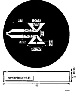
appealing advantages over microstrip antennas: they provide wider bandwidth, good imped- ance matching, and the possibility of obtaining bidirectional [2] and unidirectional [3] radiation patterns. Slot antennas are usually fed by coplanar waveguide (CPW). Coplanar waveguides are pref- erable to microstrip lines for several reasons, such as their low dis- persion, the ability to effectively control their characteristic impedance, and their ease of integration with active devices. In this Letter, a bow-tie slot antenna fed by CPW is introduced. The analysis is carried out both theoretically and experimentally. In the following Section, the return loss and the radiation patterns of the proposed antenna are presented and briefly discussed. The effect of the antenna geometry on the results is also investigated.cordierite (~,=4.9)
I-
40 -I
Fig. 1 Geometry ofproposed bow-tie antenna with flare angle of 90 and 60
All dimensions are in millimetres, dimensions between braces corre- spond to case of 60"
I I I I
frequency,GH(z
E 4 Fig. 2 Measured and calculated return loss against frequency for bow- tie(90) and bow-tie(60)
simulation measurements
_ _ _ measurements
- _ _ _
Results and discussions: The geometry of the proposed bow-tie antenna is shown in Fig. 1. Two bow-ties with approximately the same physical aperture sizes and different flare angles are imple- mented and compared. Fig. 1 shows the geometry of the bow-tie antenna with flare angles of 90" and 60'; the dimensions in the braces correspond to a bow-tie antenna with a flare angle of 60". These antennas will be referred to as bow-tie(90) and bow-tie(60). Both of them are realised on a 500pn thick Cordierite [4]