1540 IEEE TRANSACTIONS ON MICROWAVE THEORY AND TECHNIQUES, VOL. 44, NO. 9, SEPTEMBER 1996
Analysis
eeding
Structures
Wave Antenna
IYu-De Lin, Jyh-Wen Sheen, and Ching-Kuang C . Tzuang, Senior Member, IEEE
Abstract-Three arrangements of the feeding structure for the excitation of a microstrip leaky wave antenna are proposed and investigated in this paper. A full-wave spectral domain integral equation method combined with the fundamental mode sampling technique is applied to determine the reflection coefficient of the excitation source. Tabulation technique is used to reduce the computational effort. Dependence on structural parameters such as line width, line spacing and overlap length is fully analyzed to obtain the design criteria for a microstrip leaky wave antenna. Additionally, an experimental setup is used to check the validity of our numerical results and verify the radiation nature of the microstrip line first higher-order mode.
I. INTRODUCTION
LTHOUGH the microstrip line is not a low loss guide, with its features of low profile, structural simplicity, eas- ier fabrication, and suitability for integrated design, the leaky wave antenna based on it is worthy of further consideration for applications as an integrated antenna. A microstrip leaky wave antenna with first higher-order mode excitation radiates power in the narrow frequency regime before cutoff. The radiation main-beam depends on the operating frequency. Therefore it can be used as a frequency-scanning antenna [l]. The propagation properties of microstrip line higher-order modes were first studied by Ermert [ 2 ] , [ 3 ] . He used an accurate mode-matching method to find the propagation charateristics
of the dominant mode and first two higher-order modes, but he failed to obtain real solutions near the cutoff of the higher- order modes. He therefore called the range as “radiation” range, but did not further explain. Oliner and Lee clarified the confusion of properties of microstrip line higher-order modes and showed that the radiation occurs in two forms, surface wave and space wave [4]. In [5] Oliner pointed out that if the microstrip line has a top cover, the power radiated into space wave will increase with increasing height of the top cover. When the top cover is removed, most of the power radiates into space wave. The fact indicates the efficiency of the microstrip
leaky wave antenna. Recently, Nyquist proposed a rationale for the specification of the radiation spectrum associated with open microstrip line and made clear the radiation properties of the open microstrip line higher-order mode [6].
There is much effort made to characterize the propagation properties of microstrip line higher-order modes, but little about the excitation of these modes. The principles of design Manuscript received September 29, 1995; revised May 24, 1996. This work was supported in part by National Science Council under Grants NSC 84- 2221-E-009-012 and NSC 84-NSPO-A-RDD-009-01
The authors are with the Institute of Communication Engineering, National Chiao Tung University, Hsinchu, Taiwan, R.0 C
Publisher Item Identifier S 0018-9480(96)06383-1.
001 8-9480/96$05
of feeding structures for this leaky wave antenna are the sup- pression of dominant mode and the excitation of only the first higher-order mode. Menzel had proposed a sucessful method for the excitation of the microstrip line first higher-order mode in [7]. He used an asymmetric feed arrangement with a sequence of transverse slits on the center of the microstrip line to suppress the microstrip line dominant mode. In this paper, we propose three arrangements of feeding structure for the microstrip leaky wave antenna: one is the slotline-fed struc- ture; another is the coupled-slotlines-fed structure; and another one is the coplanar-strips-fed (CPS-fed) structure. These types of excitation assure the suppression of the dominant mode and obtain higher efficiency. The slotline-fed structure and the CPS-fed structure had been investigated in our previous paper [8]. But due to the limitation of length, the analysis methods and the physics underlying the design of feeding structures were not clearly described. Also, the comparison between the measured results and numerical results was incomplete. So some confusions might arise and they will be clarified in this paper. In this paper, for full consideration of the physical phenomena, we employ a full-wave spectral domain integral equation technique and the method of moments to find the reflection coefficient‘of the excitation source. Additionally, the fundamental mode sampling technique [9] is used to simulate the excitation mode and the leaky mode. In our analysis, the bases used to model the higher-order modes near the discontinuities, the incident mode, the reflected mode and the transmitted mode are chosen to be the same. This makes the types of bases used in the moment method fewer and simpler. By employing the tabulation technique, various dimensional parameters of structure are analyzed efficiently to obtain the optimum design of the feeding structure. In Section I1 of this paper, the radiation characteristics of microstrip line higer order modes are described and verified by our experimental setup. In Section 111, three types of feeding structure are proposed and the methods to excite the excitation soures, slotline mode, coupled slotlines mode and CPS mode are also described. In Section IV, the numerical techniques used to simplify the problems and accelerate the computation are pre- sented. In Section V, the numerical results are fully analyzed to obtain the design criteria and an experimental verification is also performed to validate our numerical results.
11. RADIATION CHARACTERISTICS OF MICROSTRIP LINE HIGHER-ORDER MODES Possible applications of planar transmission line higher- order modes as leaky wave antenna have been investigated .OO 0 1996 IEEE
LIN et al.: ANALYSIS AND DESIGN OF FEEDING STRUCTURES FOR MICROSTRIP LEAKY WAVE ANTENNA 1541
18 t 4 6
input port radiating element output port
D micmtrip line dotlie
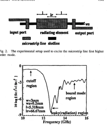
Fig. 2. The experimental setup used to excite the microstrip line first higher order mode.
14
.
,\...
,.
.
.12
Frequency (GfIz)
Fig. 1. Behavior of normalized phase constants and attenuation constants of the microstrip line first higher-order mode.
intensively both theoretically and experimentally in [2]-[7],
[lo]. In [7], experimental verification of a microstrip line higher-order mode antenna was conducted without explanation of physics underlying the design of the antenna. In [4] and
[ 5 ] , Oliner explained the physics underlying the leaky wave
antenna design constructed in [7], and presented analysis data for the antenna design. The nature of the operation of leaky wave antennas comes from the cutoff property of the higher- order mode of planar transmission lines, as explained in [4]. As the frequency decreases, the propagation constants of the higher-order mode of planar transmission lines decreases from the bound region to the radiation region and then to the cutoff region. In the cutoff region, since the microstrip line is not a closed structure, the propagation constant
( p
in e--3p+) is not a pure imaginary number; instead, the propagation constant will change from ,6 to ,B-
l a . It is a complex number with a small real part, ,B, and a large imaginary part, l a , as shown in Fig. 1, indicating that the mode is not strictly cutoff, but a very small portion of energy still propagates down the transmissiom line. There are several analysis methods to obtain the complex propagation constant. In [2], the mode-matching method is used. In this paper, we use the familiar spectral domain analysis with appropriate choice of branch cuts and integration contours as in [lo]. Depending on the relation between the propagation constants of the guided mode, the propagation constant of the surface wave of the surrounding structure, and the wavenumber in free space, the higher-order modes of microstrip line can be divided into the following four frequency regions:1)
p
>
ps,
a = 0, bound mode region;2)
ps >
,l?>
Ico, small a, surface wave leakage region; 3) Ic0>
/I, small a , surfave wave and space wave leakageregion;
4) IC0
> P,
large a, cutoff region./3 is the propagation constant of the microstrip line higher- order mode,
,&
is the propagation constant of the surface wave mode of the surrounding structure, and ko is the wavenumber in air. In frequency region d, large a of the complex prop-agation constant does not mean that the radiation is strong for the microstrip line higher-order mode. Instead, the higher- order mode is reactive and below cutoff [5]. A check on
-9 F....,....I.
10 12 14 16
Frequency (GIEZ)
Fig. 3. ment.
Power dissipation for different propagation regions in our experi-
the currents and Poynting vector reveals that the mode can propagate very small real power in the guided direction. Ini this paper, an experimental setup shown in Fig. 2 is usedl to identify the radiation nature of the microstrip line first higher-order mode. The experimental setup is composed of
two pairs of microstrip line and slotline transition circuits, and a radiating microstrip element. The twisted structure is used to enhance the suppression of the dominant mode. The distinction of mode nature in different propagation regions as shown in Fig. 3 can be shown by inspecting the power conservation in our experimental setup with the same dimensional parameters as in Fig. 1.
111. PROPOSED FEEDING STRUCTURES
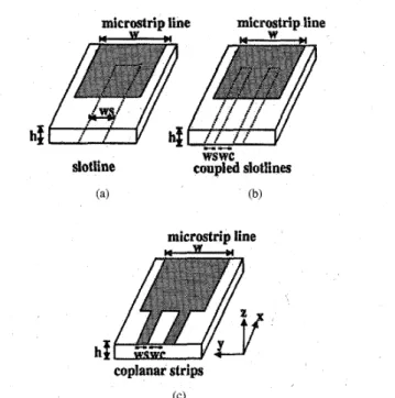
The best way to excite the microstrip leaky wave antenna is that only the first higher-order mode is excited and the dominant mode is fully suppressed. The dominant mode of microstrip line is the even mode of microstrip structure with magnetic wall symmetric plane. The first higher-order mode is the odd mode with electric wall symmetric plane. These two modes have different symmetry properties. The feeding structures proposed in this paper, as shown in Fig. 4, employ these properties to excite the desired first higher-order mode and to suppress the dominant mode. The excitation sources in these three feeding structures all have the same symmetry property as the microstrip line first higher-order mode. Thle
structure in Fig. 4(a) consists of microstrip line and slotline. The slotline mode can be excited by microstrip line dominant mode in the orthoganal direction as shown in Fig. 2. The structure in Fig. 4(b) consists of microstrip line and coupled slotlines. The coupled slotlines mode can be excited by a
1542 IEEE TRANSACTIONS ON MICROWAVE THEORY AND TECHNIQUES, VOL. 44, NO. 9, SEPTEMBER 1996
k
slotline to coupled slotlines transition circuit. The structure in Fig. 4(c) consists of microstrip line and CPS. The CPS mode can be excited by a microstrip line 180” hybrid or a coplanar waveguide (CPW) to CPS transition [ l l ] . With their symmetry properties of field distributions different from that of the microstrip line dominant mode, these three feeding structures can fully suppress the microstrip line dominant mode. Impedance matching at the input port of excitation sources (either slotline, coupled slotlines or CPS) can be achieved by using tapered feeding lines.
IV. FULL-WAVE SPECTRAL DOMAIN ANALYSIS In this paper, we use the spectral domain integral equation technique to analyze the proposed feeding structures. Here, the CPS-fed structure is used as an example to describe the analysis method. For the slotline-fed and coupled-slotlines-fed structures, the analysis can be carried out by using similar procedure. The geometric configuration of the CPS-fed struc- ture is shown in Fig. 4(c). Following the procedure in [12] we can obtain the spectral domain Green’s function G,,, G,,,
G,,, and G,,. As a result, the tangential electric field on the surface S,, gray area in Fig. 4(c), is formulated in the integral equations
where
and E,, E, are tangential electric fields on S,. G,, and G,,
are the dyadic Green’s function components due to x-directed infinitesimal electric dipole and G,, and G,, are the dyadic Green’s function components due to y-directed infinitesimal electric dipole at z = h in space domain. J , and J , are surface electric currents on S m .
To solve the spectral domain integral equation, we first expand the surface current on surface S , as the sum of
reflected current modes, transrmtted current modes and local current bases with unknown coefficients, and incident current modes with predetermined coefficients
n m
where n, m are the locations of x-directed and y-directed
local current bases; J;”“?
JY
are x-directed and y-directed incident current modes: J Z f , J F f are x-directed and y-directed reflcted current modes; J:”,Jira
are x-directed and y-directed transmitted current modes;I?
is the reflection coefficient; Tmierostri~ line microstrip line
wswc
slotline coupled slotiines
(a) (b)
microstrip line
coplanar strips (C)
Fig. 4 Three feeding structures for the excitation of microstrip line first higher-order mode. (a) The slotline-fed structure. (b) The coupled-slotlines-fed structure. (c) CPS-fed structure.
is the transmission coefficient; I:, Iy” are coefficients of x-
directed and y-directed local current bases. After the above current expansion, we substitute (4) into (1) and (2). Then by forcing the boundary condition that the tangential electric field on surface Sm must be zero, we can arrive at the surface integral equations in the forms of
F (G,, J z f
+
G x y J T f )+
T (G,,J p
+
G,,Jp)
1r
(cy,
JZf
+
G,,Jrf)
+
T ( G,, J?+
G,, J;”)JJ
i
7 n m = -JJ
[ G y , ~ F C+
G,, J F ] dS,. (6) About the choice and the layout of the basis functions, we use the module concept proposed in [ 131 and the fundamental mode sampling technique proposed in [9] to simplify the problem. The layout of the basis functions in CPS-fed case are shown as Fig. 5(a). In moment method in [13], an exponential term is used to represent the propagation mode, resulting in complexity in modeling and more computational effort needed. In this paper, we use an expansion in terms of local basis functions (piecewise sinusoidal functions or triangular func- tions) to represent the exponential ?erm as shown schematicallyLIN et al.: ANALYSIS AND DESIGN OF FEEDING STRUCTURES FOR MICROSTRIP LEAKY WAVE ANTENNA 1543
local higher order mode region (local bases)
Y
mode region leaky mode region
(a)
(b)
Fig. 5.
interpretation of fundamental mode sampling technique.
(a) The layout of bases for the CPS-fed structure. (b) The qualitative
in Fig. 5(b). This method is called the fundamental mode sampling technique in [9]. For example, we can represent the e--@x by the following equation:
I - - 3 P G l
n - e
where I, is the amplitude of basis functions, B represents the
basis used for simulation, H is half width of the local basis
function, x, is the location of the basis function and nmax is the number needed to represent the propagation mode to obtain numerical convergence. Typically, we can choose H about the size of X/30 to obtain the convergent solution.
Then we use a nearly Galerkin method [13] to transform the integral equations, (5) and (6), into matrix equations similar to that in [9] and obtain the reflection coefficient of excitation source by solving the matrix equations. The only difference between the modified Galerkin method and the traditional Galerkin method is that the testing functions for the propagating modes, incident mode, reflected mode and transmitted mode are chosen as local bases function with the same transverse dependence as the propagating modes [ 131. The transverse dependences and propagation constants of propagating modes are precalculated in our analysis.
In this paper, the structural parameters such as line width and line spacing are widely varied to obtain the structure that has optimum efficiency. If the integrals are recalculated when the structural parameters are changed, it is very time- consuming. To avoid redundant calculations, we employ the
tabulation technique to form tables for the reactions between the basis fuctions and the testing functions with different relative positions. To facilitate the creation of these tables, two types of local basis fuction are used to model the higher- order modes near the discontinuity and to expand the incident, refected and transmitted modes. One of them is X n ( z , y) in the longitudinal direction and the other is Y"(z,y) in the transverse direction. They are in the form of the following equations:
(9)
where ti and t3 are the centers of basis functions rL,y and s ; , ~ .
d, and uy are the length and the width of Xn(z,y). d, and u, are the length and the width of Y m ( z , y ) . By using such choice of basis functions, only three types of double integrals are needed and only three types of tables must be created. All the reactions between different modes can be obtained from these tables. Therefore, only one round of calculations of the integrals is needed for various structural parameters. In CPS- fed case, we need to create the tables of reaction about the bases in the module as shown in Fig. 6(a). Here, Zinc and Ztran
are the lengths to represent incident, refected and transmitted modes. Wmax is the maximum width of microstrip line or
CPS's in our analysis. After the creation of the tables, other feeding structures such as those shown in Fig. 6(b) and (c) can be also analyzed without recalculation of integals.
Additionally, we consider the even and odd function sym- metric properties of spectral domain Green's functions and the geometric symmetric properties of basis functions to reduce the number of matrix elements and to improve the computational efficiency in spectral domain integration. The Green's functions, matrix blocks and integrals involved in this analysis are well known [9], [13] and are not reiterated here.
V. NUMERICAL RESULTS AND MEASUREMENT
The efficiency of excitation for the microstrip line first higher-order mode fed by slotline, coupled slotlines and CPS with various dimensional parameters is investigated in this section. The numerical results are compared with those in [7]. The operational frequency is 7 GHz, chosen in the center of the radiation region as shown in Fig. 7. The numerical results, and experimental data are summarized as follows.
A. Slotline-Fed Structure
The structural parameters of the slotline-fed structure in- clude the width of the slotline and the overlap length between microstrip line and slotline. The typical pattern of efficiency., exhibiting the periodic change due to various overlap lengths is shown in Fig. 8. The period is almost half guided wavelength1 of slotline. The influence of the slotline width is shown in
~
1544 IEEE TRANSACTIONS ON MICROWAVE THEORY AND TECHNIQUES, VOL. 44, NO. 9, SEPTEMBER 1996
n Y U linc ltran 0.25
4
0 0.2 0.4 0.6 0.8 1 Y CPS microstrip line CPS microstrip line ws wc W (c)Fig. 6. The qualitative interpretation of tabulation technique for the CPS-fed structures. (a) The maximum range, of bases used to create the tables. (b) The layout of bases in narrower strip spacing case. (c) The layout of bases in wider strip-spacing case.
4 6 8 10 12'
Frequency
(GI%)
Fig. 7. Behavior of normalized phase constants and attenuation constants of the microstrip line first higher-order mode with same dimensional parameters as [7].
Fig. 9 with the optimum overlap length. They shoy that the slotline-fed structures have better efficiencv in wider slotline
Fig. 8.
the unit of slotline wavelength in the slotline-fed structure.
The normalized reflected power as a function of overlap length in
I . , * . , . . . *
2 4 6 8 1 0 1 2
WS(") Fig. 9.
the optimum overlap lengths, are used in the slotline-fed structure. The normalized reflected power as a function of slotline width when
cases. When the width is beyond 8 mm, the efficiency is better than that in [7]. The optimum overlap lengths with different slotline widths are shown in Fig. 10. They are between A,/4
and As/4. Here, A, is the guided wavelength of the microstrip line first higher-order mode and A, is the guided wavelength of the slotline dominant mode. The phenomenon can be explained as follows. The transverse electric fields have maximum values at the open end of the microstrip line and As/4 from the short end of the slotline. Therefore, better coupling from the feeding slotline to the microstrip line can be achieved by placing these positions close to each other. But, the guided wavelengths of these two lines, A, and A,, are different, as shown in Fig. 10. Therefore, the, optimum overlap length is between
X,/4 and X,/4. Additionally, from Fig. 10 we find that the optimum overlap lengths in narrow slotline cases are longer than those in wide slotline cases and the optimum overlap lengths in narrow slotline cases approach to X,/4. It is due to that the shorted slotline is not ideally shorted but has an end inductance. The end inductance can be transformed into an equivalent length by transmission line theory. In [9], it is shown that narrower shorted slotlines have smaller end inductance and shorter equivalent length. It results in that longer overlap length is needed in narrower slotline case. In this paper, every optimum overlap length is obtained in the unit of X,/30 of its corresponding slotline mode. And the corresponding wavelengths due to different slotlines are different. These two reasons result in that the overlaD lengths
LIN et al.: ANALYSIS AND DESIGN OF FEEDING STRUCTURES FOR MICROSTRIP LEAKY WAVE ANTENNA
-("I
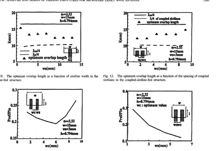
Fig. 10. The optimum overlap length as a function of slotline width in the slotline-fed structure. d m n l h~.794mt11 0.15 . ' * ' * a * a . 0 2 4 6 8 1 0 w c ( m )
Fig. 11. The normalized reflected power as a function of the spacing of coupled slotlines in the coupled-slotline-fed structure.
are given discretely and do not change monotonously, but they are very close to the real optimum overlap lengths.
B. Coupled-Slotlines-Fed Structure
The structural parameters of the coupled-slotlines-fed struc- ture include the slot width of the coupled slotlines, the slot spacing of the coupled slotlines and the overlap length between the microstrip line and the coupled slotlines. The efficiency in the case of the coupled slotlines-fed structure is similar to that of the slotline-fed structure. The typical pattern of efficiency, exhibiting the periodic change due to various overlap lengths is similar as shown in Fig. 8. The period is also almost half guided wavelength of coupled slotlines mode as in the slotline- fed case. The influence of slot spacing is shown in Fig. 11 with optimum overlap length. They show that the optimum slot position is close to but smaller than a quarter width from the edge of microstrip line. For coupled slotlines with different slot width, similar variation due to different slot spacing as shown in Fig. 11 can also be observed. The optimum overlap lengths with different slot spacings are shown in Fig. 12. They also show that the optimum overlap length is between
X,/4 and X,,/4 (Acs is the guided wavelength of the coupled slotlines mode). Also due to that the shorted coupled slotlines with narrower slot spacings have longer equivalent length, the optimum overlap lengths are shorter in narrower slot spacing cases than those in wider slot spacing cases. And the influence of the slot width is shown in Fig. 13 with the optimum overlap
1545
1
Fig. 12. The optimum overlap length as a function of the spacing of coupled slotlines in the coupled-slotline-fed structure.
---1 ws(mm) 7
Fig. 13. The normalized reflected power as a function of slot width when the
optimum overlap lengths and slot spacings are used in the coupled-slotline-fed structure.
length and slot position. They show that wider slot width has better efficiency. Additionally by comparing our numerical results, we find that slot width dominates the improvement in efficiency and the variation in efficiency due to different slot spacing is very small when the slot width is wide enough. Also, due to that the shorted coupled slotlines with wider slot width have longer equivalent length, the optimum overlap lengths are shorter in wider slot width cases than those in narrower slot width cases.
Finally by comparing the slotline-fed structure with the coupled-slolines-fed structure, we find that the efficiency ob- tained by the coupled slotlines-fed structure is better than that by the slotline-fed structure when the slot width is the same. But the coupled-slotlines-fed structure is more complicated. It need a slotline to coupled slotlines transition circuit. However, it might be a better choice to achieve the desired efficiency without using impractically wide slotline.
C. CPS-Fed Structure
The structural parameters of the CPS-fed structure include the strip width of CPS and the strip spacing of CPS. The efficiency due to different strip widths of CPS is shown in Fig. 14. We find that the efficiency is higher when the strip width is narrower. It is due to that there is smaller discontinuity in transverse variation of currents when the feeding points are narrower. And the efficiencies are better than those in [7] for
1546 IEEE TRANSACTIONS ON MICROWAVE THEORY AND TECHMQUES, VOL. 44, NO. 9, SEPTEMBER 1996
..-.
U.141 I EF2.32 w=15mm h=0.794mm r: 0.11 .de!
% kO.08 Fig. 14.coplanar strips in the CPS-fed structure.
The normalized reflected power as a function of the width of
w
0.25
t
I
Fig. 15.
coplanar strips in the CPS-fed structure.
The normalized reflected power as a function of the spacing of
all cases in Fig. 14. The effect caused by different spacings
of strips is also shown in Fig. 15 with strip width equal to 3.75 mm. When different strip widths are used, similar effect as shown in Fig. 15 can be observed. It is shown that the optimum positions of the strips of CPS are almost at a quarter width from the edge of microstrip line. Considering all the effects of the structural parameters presented above, a very efficient CPS-fed structure can be obtained by using narrower strips at their optimum positions.
Finally, we compare the results of the CPS-fed structures with those of slotline-fed ant coupled-slotlines-fed structures. We find that the efficiency is better for CPS-fed structures. Although CPS-fed structure is better in efficiency than the slotline-fed and coupled-slotlines-fed structures, it needs either a microstrip line 180' Hybrid or CPW to CPS transition to generate the CPS excitation mode. This transition circuit must be properly designed to obtain better efficiency in the overall circuit.
D. Measurement
In this paper, an experimental setup as shown in Fig. 2 is performed to check the validity of the analysis results obtained. The propagation property of the radiating element is shown in Fig. 1. Its efficiency for various overlap lengths and operational frequencies is shown in Fig. 16. The wavelengths of slotline modes and microstrip line first higher-order modes are listed in Table I. Obviously, the efficiencies in Fig. 16 are
TABLE I
WAVELENGTHS OF MICROSTRIP LINE FIRST HIGHER-ORDER MODE AND
SLOTLINE MODE FOR DIFFERENT OPERATIONAL FREQUENCIES IN R G . 16
I(") Fig. 16.
different operational frequencies in the slotlines-fed structures.
The normalized reflected power as a function of overlap length with
10 12 14 16
Frequency (GHz)
Fig 17
iment ( I , = 66.67 mm in Fig. 2).
The power dissipation with different overlap lengths in our exper-
better than that with low dielectric constant in the above anal- ysis, shown in Fig. 8. But they do not mean necessarily that they have higher radiation efficiencies, since more power may leak into the surface wave in high dielectric constant layer. As expected, the positions near X,/4 are proper positions to overlap in narrower slotline cases. But unlike cases with low dielectric constant layer, another local minimum value in efficiency before X,/4 is observed. The phenomenon is due to that the wavelenghs of the slotline and the microstrip line first higher-order mode are more different than those in low dielectric constant cases, resulting in more complex field distribution and power coupling in the overlap region. Finally, the measured results are shown in Fig. 17 to validate our numerical results. They show that the power dissipation is large with the overlap length of 5.318 mm, and therefore the measured data agrees well with OUT numerical results in Fig. 16. In Fig. 17, the cutoff region is in the lower frequency
LIN et al.: ANALYSIS AND DESIGN OF FEEDING STRUCTURES FOR MICROSTRIP LEAKY WAVE ANTENNA 1547
region, where there is almost no power dissipation. In the middle frequency region, the larger power dissipation is due to the radiation. The ripple in higher frequency region is due to the resonance of bound microstrip line first higher-order mode. A 3 dB power dissipation due to the conductor loss is also observed.
VI. CONCLUSION
The design rules of the feeding structures for the microstrip line leaky wave antenna are proposed after our analysis. In the slotline-fed structure, optimum excitation is obtained with wider slotline and with overlap length between X,/4 and
X,/4 in low dielectric constant structures widely used in antenna application. But the use of wider slotline must satisfy the condition that no extra higher-order mode with the same symmetry property of the slotline dominant mode is excited. In the coupled-slotlines-fed structure, the optimum excitation is obtained with wider slot width, proper slot position at near a quarter width from the edge of the microstrip line, and overlap length between X,/4 and X,/4 in lower dielectric constant structures. The efficiency obtained by the coupled-slotlines-fed structure can not be much better than that of the slotline- fed structure. This feeding structure is more complicated. It needs a slotline to coupled slotlines transition circuit. But the use of coupled slotlines-fed structure can achieve the desired efficiency without using impractically wide slotline. In CPS- fed structure, the optimum excitation is obtained with narrower strip width and with the strip positions almost near a quarter width from the edge of the microstrip line. Although we find that the CPS-fed structure is better in efficiency than the slotline-fed and coupled-slotlines-fed structures, it needs either a microstrip line 180’ hybrid or CPW to CPS transition to generate the CPS excitation mode. This transition circuit must be properly designed to obtain better efficiency in the overall circuit.
REFERENCES
R. C. Johnson, Antenna Engineering Handbook. New York McGraw- Hill, 1993.
H. Ermert, “Guided modes and radiation characteristics of covered microstrip lines,” Archiv fur Electronik und Ubertragungstechnik, vol. 30, pp. 65-70, Feb. 1976.
H. Ermert, “Guided modes and radiation characteristics of planar waveguides,” Microwave, Optics and Acoustics, vol. 3, pp. 59-62, Mar. 1979.
A. A. Oliner and K. S. Lee, “The nature of the leakage from higher- order modes on microstrip line,” in 1986 ZEEE MTT-S Znt. Microwave Symp. Dig., Baltimore, 1986, pp. 5 7 4 0 .
A. A. Oliner, “Leakage from higher modes on microstrip line with application to’antenna,” Radio Sci., vol. 22, no. 6, pp. 907-912, Nov. 1987.
J. M. Grimm and D. P. Nyquist, “Spectral analysis considerations relevant to radiation and leaky modes of open-boundary microstrip transmission line,” IEEE Trans. Microwave Theory Tech., vol. 41, pp. 150-153, Jan. 1993.
W. Menrel, “A new traveling-wave antenna in microstrip,” Archiv fiir Electronik und Ubertragungstechnik, vol. 33, pp. 137-140, Apr. 1979.
[8] Y. D. Lin, J. W. Sheen, and C. K. C. Tzuang, “Analysis and design of feeding structures for microstrip leaky wave antenna,” in 1995 IEEE MTT-S Int. Microwave Symp. Dig., Orlando, FL, 1995, pp. 149-152. [9] T. Rozzi, A. Morini, A. Pallotta, and F. Moglie, “A modified dynamic
model for planar microwave circuits,” IEEE Trans. Microwave Theory Tech., vol. 39, pp. 2124-2153, Dec. 1991.
[lo] J. S. Bagby, C. H. Lee, D. P. Nyquist, and Y. Yuan, “Identification of propagation regimes on integrated microstrip transmission lines,” IEEE
Trans. Microwave Theory Tech., vol. 41, pp. 1887-1894, Nov. 1993. [ l l ] C. H. Ho, L. Fan, and K. Chang, “Broad-band uniplanar hybrid-ring
and branch-line couplers,” IEEE Trans. Microwave Theory Tech., vol. 41, pp. 2116-2125, Dec. 1993.
[12] T. Itoh, Numerical Techniques for Microwave and Millimeter- Wave Passive Structures.
[I31 S . C. Wu, H. Y. Yang, N. G . Alexopoulos, and I. WOW, “A rigorous
dispersive characterization of microstrip cross and T junctions,” IEEE
Trans. Microwave Theory Tech., vol. 38, pp. 1837-1844, Dec. 1990. New York Wiley, ch. 3, 1989.
Yu-De Lin was born in Lotnng, Taiwan, on Feb-
ruary 27, 1963. He received the B.S. degree in electncal engineering from National Taiwan Uni- versity in 1985, and the M.S. and Ph.D. degrees in electrical engineering from The University of Texas at Austin in 1987 and in 1990, respectively.
In 1990, he joined the faculty of Department of Communication Engineering, National Chiao Tung University, HsinChu, where he is now an Associate Professor. His current research interests include numerical methods in electromagnetics, charateri- zation and design of microwave and millimeter-wave planar circuits, and analysis and design of microwave and millimeter-wave antennas.
Jyh-Wen Sheen was born in Lotung, Taiwan, on
October 10, 1968. He received the B.S. degree in control engineering from the National Chiao Tung University, Hsinchu, Taiwan, in 1991, and the M.S. and the Ph.D. degrees in communication engineering from the same University, in 1993 and 1996, respectively.
He currently conducts the analysis and design of various planar type leaky wave antennas, and the investigation of surface wave leakage phenomena of nniplanar transmission line. His research interests include the analysis and design of microwave passive circuits and the development of numerical technique in electromagnetic,
Ching-Kuang C. Tzuang (S’84-M’864M192)
was born in Taiwan on May 10, 1955. He received the B.S. degree in electronic engineering from the National Chiao Tung University, Hsinchu, Taiwan, in 1977, the M.S. degree from the University of California at Los Angeles, in 1980, and the Ph.D. degree in electrical engineering from the University of Texas at Austin, in 1986, where he worked on high-speed transient analyzes of monolithic microwave integrated circuits.
From 1981 to 1984, he was with TRW, Redondo Beach, CA, working on analog and digital monolithic microwave integrated circuits. Since 1986, he has been with the Institute of Communication Engineering, National Chiao Tung University, Hsinchu, Taiwan. His research activities involve the design and development of millimeter-wave and design of various qnasioptical active integrated antennas.