Indoor guiding system
for the visually impaired
Name
Student ID
School
Department
Year of study ITSC Email
LEE Lok Yin
SENG
CPEG
4
KHANG
Minsoo
SENG
CSE
4
Advised by Dr. Desmond Yau-chat TSOI
1. Introduction
1.1 AbstractVision plays a significant role in our daily lives and is often taken for granted by many. The moment we step outside our home, we rely on our vision to avoid potential pitfalls, obstacles and also to navigate ourselves to our destination. However, one need not look beyond his/her home to understand the role of vision in daily lives. Even within the four walls of our living room, we all rely on our vision to avoid furniture and retrieve daily essential items (e.g. tissue, water bottles, wallets, etc). Based on [1] by the World Health Organization (WHO) in 2019, over 2.2 billion individuals around the world suffer from visual impairment of varying degrees. Such a high proportion of individuals suffering from vision difficulties certainly prompts for solutions to ameliorate the challenges they face in day to day activities.
Some of the main existing solutions are: walking sticks, guide dogs and dependence on a helper. However, these solutions each have their own shortcomings which the affected individuals have to tolerate in their daily lives. While walking sticks could serve the need for navigation, it is certainly ineffective when the visually impaired seeks to retrieve a particular item on a table. Guide dogs on the other hand require intensive dedicated training on the dog to retrieve a particular item. While employing a separate helper would resolve the previously mentioned shortcomings, it is certainly not scalable and not everyone would be willing and able to afford this option.
As such, we have decided to design a guiding car system which serves to navigate the visually impaired individuals to retrieve specific items of their choice in a household setting. In this system, when the user provides a voice command such as “water bottle”, the command is picked up by the system which then registers the target object as the guiding car’s destination. The system then utilizes the top down camera installed on the household’s ceiling to locate the target object and communicate with the guiding car. With automatic path planning and a regular beeping signal, the car navigates the user towards the target object.
Unlike other alternatives such as employing a dedicated helper for the visually impaired which could potentially incur a high regular expenditure, our system serves as a more sustainable and affordable solution by leveraging on IOTs with most of the cost being a one-off expenditure. As opposed to facing the risk of exposing our private life to a stranger in the event of employing an external helper, our guiding car system runs in a closed system and does not require online processing to assist the visually impaired. As such, through our guiding car system, the users are able to experience greater privacy within their households.
In the current world, there are many separate solutions available pertaining to voice recognition, object detection, navigation and vehicle control systems. However, given the context of household setting and the purpose of guiding the visually impaired, there are numerous objectives that are unique to this system such as high response rate with high accuracy, limited lighting in the household environment for object detection and more. Motivated by this, we aim to design and develop a guiding car system by synchronizing, improving and optimizing the various solutions and customizing them to address these objectives.
1.2 Objectives
The primary objective of this guiding system is to create an indoor system that reduces the inconvenience of visual impairment people reaching necessities of life. This system can be separated into the following three objectives.
1. Locate the different life necessities accurately in real-time
2. Create an agile and responsive guiding car to navigate users to target location
3. Develop an user-friendly and intuitive interface for the user
4. Integrate an autonomous pipeline for the first-time user customization
2. Methodology
2.1 Design
System design
Figure 1, Diagram of information flow between different components of the project
The design of the guiding car system consists of 4 main components, namely: Microphone, Top-down view camera, Central computer and the Guiding car. The microphone and the camera mainly serve to capture the household environment along with the user’s voice commands while the central computer provides the necessary computations to navigate the guiding car. Figure 1 shows a brief outline of the flow while Table 1 lays out the functions of each of these components:
Device / component Function
Microphone Receive voice command from user and transfer the signal to central computer for further processing
Top-down view
camera Capture images of the indoor environment in a top-down view, including stereo vision images, and transfer them to the central computer for further processing.
Central computer Process the voice signal and image data with machine learning models, to obtain the target necessity indicated by the user and the location of the object in the indoor environment respectively.
Calculate the path to be taken by the guiding car from its current location to the location of the target necessity and transfer the path planned to the guiding car.
Guiding Car Navigate along the path received wirelessly from the central computer. The guiding car emits a regular beeping sound signal as a source of guidance for the user.
Table 1, Table of components included in the project and their respective functions
Figure 2 below displays a brief description for each of the components in our system
Figure 3, Detailed information flow between different components of the guiding car system
Based on the design described of our project, Figure 3 displays a more detailed information flow diagram of the guiding car system.
2.2 Implementation
Based on the system design discussed under the Design section, our guiding car system’s implementation could be split into four broad categories: wireless controllable guiding car, object localization in 3-dimensional space, voice recognition-based user interface, path planning & navigation.
2.2.1 Wireless controllable guiding car
To create a vehicle to guide users towards their target, the guiding car is required to move
with precision and agility. As shown in figure 4, we have incorporated high performance
components including STM32 microcontroller unit, optical encoder, bluetooth 4.0, lithium
polymer battery and a buzzer to provide the necessary functionalities.
Figure 4, Diagram outline of the guiding car
2.2.1.1 Main control system using STM32 microcontroller
STM32 microcontroller unit (STM32F103C8T6 MCU) has been incorporated as the main
control unit behind speed control, navigation and wireless communication for the vehicle.
This MCU was chosen for its adequate processing power of 72MHz core frequency and
more importantly its reliable performance. We have also utilized pulse width modulation
(PWM) for motor and buzzer control and Universal Synchronous Asynchronous Receiver
Transmitter (USART) in the bluetooth communication.
2.2.1.2 Speed control by optical encoder
To ensure stability and accuracy in the vehicle’s navigation along the planned path, the
driving system of the vehicle was installed with a 1024 resolution optical rotary encoder
which records the relative position of the wheels during movement. Based on the PWM
motor control and the feedback from the encoder, we have created a closed loop system
with a Proportional-Integral-Derivative (PID) controller that controls velocity and distance
coverage of the vehicle accurately and within a narrow error margin of millimeters.
2.2.1.3 Battery powering system
In consideration of our project’s application, we have realised that the battery of the
guiding car had to be non-bulky, rechargeable, long-lasting and have high capacity. To
meet a compromise between these factors, we have used a 12V 3000mAh lithium
polymer battery which can be reused multiple times and with a capacity the guiding
process of over 1000 times in one full charging.
2.2.2 Object localization in 3-dimensional space
In the application of our guiding car system, the target object had to be identified and localized in a 3-dimensional indoor space. While there are 3D object detectors available, the complexity in preparing 3-dimensional labelled images of target objects has motivated us to resort to breaking up the implementation into: 2-dimensional object detection and stereo vision. The ease of creating labelled images for target objects are crucial in the deployment stage of our system – further discussed in Section 2.2.5.1 Customize for user (object detection).
2.2.2.1 Object Detection
The object detection aims to detect target necessities from images captured by the top-down view camera accurately and in real-time. The object detection model not only had to be efficient in computation but also effective in terms of detection accuracy. Based on comparing several real-time object detectors namely: YOLOv3, YOLOv3Tiny and Retinanet, we have chosen Retinanet for its high accuracy and lower demand in training images.
Apart from the high accuracy, achieving high performance with minimal amount of training images was a crucial factor in our application. In consideration of customizing the detection model for various target objects of each user, if the model requires a high amount of training images, it is not scalable for our use-case.
2.2.2.2 Dataset preparation and household setting
To capture the different lighting effects present in a household setting, the experimental set-up was overlaid with various shadows on top of the ceiling lighting. The ceiling lighting was approximately 2 to 2.5 meters above the ground and the experimental set-up was overlaid with shadows cast by nearby tables, chairs and people which are commonly observed in a household setting. The Figure 5 shown below is the experimental set-up we have created, including the guiding car (red square) and box-shaped obstacles (yellow square) which serves to represent various target necessities of users.
The first milestone was to determine the feasibility of Retinanet object detector in our use-case and as the model’s performance was not dependent on a specific type of object, we have decided to generalize all possible target objects as a yellow box as shown in Figure 5. Upon successful detection results of the Retinanet model, the yellow boxes were replaced with real-life necessities (discussed in subsequent sections).
2.2.2.3 Data Augmentation
Training an effective object detector often depends on the availability of a sufficiently large dataset. To address this issue especially in the context of household items, where images of users’ belongings cannot be assumed to be readily available, we had to adopt various types of data augmentation. Data augmentation is carried out after collecting a small number of labelled images of the users’ belongings.
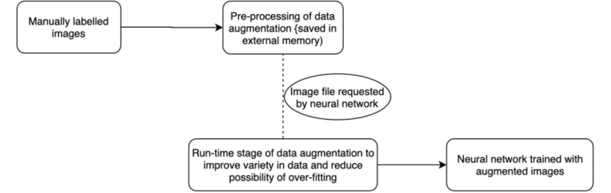
To increase the size of the training dataset without losing the meaningful aspects of the image, we have split the data augmentation to two different stages: pre-processing and run-time stage. In brief, the pre-processing stage aims to segment the target objects from the original image and overlay them on random background images to generate augmented images, while the run-time stage aims to introduce a slight variance in terms of flipping, resizing and HSV adjustments. Figure 6 shows the flow of the preprocessing stage in data augmentation starting from a small dataset of manually labelled images.
Figure 6, preprocessing stage, starting from 46 images labelled with bounding box and segmentation polygon
The preprocessing stage, as shown in the diagram above, shows how a small amount of 46 collected images can be augmented up to 3375 images through the first stage of data augmentation. The subsequent preprocessing stage introduces even more variance to each of these 3375 images during run-time, allowing the same image to be randomly translated, scaled, flipped or HSV distorted such that the object detector is trained to generalize as much as possible from the limited amount of original dataset.
Figure 7 shows an overview of how the two data augmentation stages function in the data preparation pipeline we have incorporated for training of our object detection models:
Figure 7, overview of the data preparation pipeline for training of object detection models
To test the effectiveness of our data augmentation pipeline and the feasibility of the
Retinanet model, we have tested the model with the mAP metric on the image dataset.
The model has achieved high mAP result as shown in Table 2:
Model AP of Obstacle AP of Vehicle mAP of model
Retinanet 97.79% 100.00% 98.89%
Table 2, Retinanet’s performance evaluation with mAP and AP across each of the classes
2.2.2.4 FPS and image resolution
Despite the high satisfactory performance in mAP, our Retinanet model has a comparably low FPS of approximately 5 FPS on a GTX1050Ti GPU. This is largely due to high resolution image input of 1000 x 1333. Nonetheless, the FPS of the detector was sufficient for the subsequent use-cases of our project and the resolution of image was not downscaled in order to preserve the model’s high accuracy in detection.
2.2.2.5 Stereovision
With the goal of object detection in a 3-dimensional space, we have introduced stereo vision measurement to determine the height position of objects after it has been detected by the object detector (Retinanet). We have decided to incorporate stereo vision based on binocular vision for depth measurement instead of other means such as Lidar as it was more beneficial for its high resolution and the availability of SDKs in various available products.
Figure 8, Image of ZED Stereo Vision camera [4]
From the various stereo vision products available, we have decided to use ZED stereo vision camera, as shown in figure 8 above, for its widely available SDK and its high compatibility with the NVIDIA GPU which we are utilizing for the object detector model. ZED cameras had a depth measurement range of 0.4 m to 25 m which certainly covered the range of indoor household dimensions [5]. Additional benefit was the depth measurement modes available in the ZED SDK features. Widely found in many stereo vision tasks, there is a common problem of noise / gap patches in depth images derived from the left and right cameras as shown in Table 3. These empty patches are usually compensated by rotating the stereo vision camera and overlaying the previous image with newly captured images. However, our application restricting the stereo vision
camera to be fixed as a top-down view, we had to compensate for the empty patches from the same field of view (FOV) as much as possible. The ZED SDK had a “Fill” mode feature for depth measurement and the result of this feature could be visualized in Table 3.
Depth Image in Normal mode Depth Image in Fill mode
Table 3, Sample depth image taken from ZED camera with normal and fill mode [5]
With reference to the above Table, the grayscale image has pixels with values ranging from 0 to 255 with 255 (white) indicating the closest proximity and vice versa for 0 (black). The Dark / gap patches with stark contrast around objects in normal mode are the regions which could not be measured at the specific angle of the camera but could be approximated with the “Fill” mode of the ZED camera.
As such, by installing such a stereo vision camera in a top-down view orientation, we are able to obtain the height measurement of objects in the indoor household environment. Figure9 shows the flow of how the depth calculation from the ZED camera can be combined with the object detection outcome from Retinanet to form a 3D object detection pipeline:
Figure 9, Pipeline of images captured by the left and right cameras in a ZED for object detection and depth measurement
As a concluding statement to this Object localization in 3-dimensional space section,
after the object has been localized in the top-down view and its height has been
determined by the stereo vision camera, the 3-dimensional positional information will then
be used to carry out path planning followed by navigation.
2.2.3 User interface (Voice recognition and voice feedback)
To provide a user-friendly way to utilize this guiding system, a voice recognition and audio feedback system will be implemented to allow the users to benefit with ease. For the voice recognition, the system will receive the audio data from the microphone and classify it to one of the existing classes of target necessities which were saved prior. For the audio feedback, the guiding car will use beeping sound signals to lead the user step by step.
2.2.3.1 Voice Recognition
Although there are different kinds of open-source voice recognition libraries such as SpeechRecognition by python or Cloud Speech-to-Text by google, we decided to build our own convolutional neural network (CNN) to identify audio. This decision is based on the comparison of their cost, computation power and plasticity. To consider the cost of our user interface, a CNN can be applied by keras which is a cost-free open source library while Cloud Speech-to-Text are billed in seconds of usage. It also requires a certain internet speed to communicate with the server.
SpeechRecognition by python was previously considered as an alternative to our application. However, even if it provides a different language database, its performance accuracy is not stable for non-standard speech. Some users with a special accent may result in an erroneous outcome. Therefore, we developed a pipeline by incorporating an audio convert module and CNN to achieve a high accuracy regardless of the accent / language. The simplistic design in our CNN allows the system to achieve high accuracy by customizing it for any user through custom training prior to deployment for any user (further discussed in Section 2.2.5.2 Customize for users (voice
recognition) section). Figure 10 is an illustration of transforming audio signals into different
domains prior to using them for neural network training.
Figure 10, prepossessing pipeline from the input format to a format acceptable for CNN Convolutional neural network
According to the characteristics of CNN, the convolution layers play the feature extraction role and the fully connected layers infer the classification based on the features extracted. Figure 11 shows the CNN structure used for voice recognition. To minimize the computation power and the training time required, we decided to set the feature map and max pooling layer to a small dimension of (2 x 2). We have also chosen a reasonable number of filters in each convolution layer to extract as much feature as possible for this classification task. After each convolution layer, a “Relu” activation function will be applied to address the vanishing gradient problem. The final layers of the network comprise two fully connected layers and an output layer. The dimensions of an output layer are dynamic to different users as the number of output classes could vary from user to user.
For the training and testing procedure of the voice recognition pipeline, we used a microphone to record separate audio signals with our voice. All of the soundtracks are within the 2 second length and they are classified into four groups: “book”, “bottle”, “bye bye” and “hello”. A total of 15 soundtracks were recorded for each of the groups to train the model. Prior to the training process, 30% of the data in each class was randomly selected as validation data and the rest was set as training data.
Figure 12, The training history of voice recognition network on the original data Left: the accuracy from 0 to 100 epochs, Right: the loss from 0 to 100 epochs
Due to the lightweight nature of this CNN and the dataset not highly memory demanding, we have decided to execute the training on the central computer which includes CPU I7 7700HQ and GPU GTX 1050Ti. For both the preprocessing and the training steps, the central computer required around 20 seconds to complete a total of 100 epochs of training. As the training history shown in Figure 12, at our current configuration, the training process had managed to converge within the first 60th epoch and both the accuracy and loss stabilized at 0.95 and 0.09 respectively.
In summary, our voice recognition model was able to recognize four different words at 95% accuracy with only the provision of 15 samples for each class. Such accuracy level with a reasonable amount of recording and the short training time showed great assurance of using the above voice recognition model for our project.
2.2.3.2 Audio Feedback
The additional set-ups required for audio feedback includes a microphone that is able to record the user’s voice command within the room, a speaker on the central computing device and a buzzer on the guiding car to give the guiding feedback to the user.
Figure 13, guiding procedure that operates on sound signals
For the guiding procedure, we plan to develop a user-friendly guiding procedure which is shown in Figure 13. The microphone will start recording the voice command when the volume is above a pre-set threshold. After the system recognizes the user’s command, the guiding car will approach the user and will start emitting the “beep” sound signal. The user can then follow the signal step by step while the car moves slowly in front of the user. When the guiding car successfully leads the user to the target, it will emit a long “beep” signal for 2 seconds to ensure the user stops at the proximity of the car. When the user is detected to be in the proximity of the target object through object detection, the system will inform the user on the approximate height of the object through pre-recorded audio files, such as “near shoulder level” or “near waist level”.
2.2.4 Path planning & navigation
Figure 14, sample motion of Dynamic Window Approach(Left) and A Star(Right)
To instruct a robot to move from one point to another, a path planning algorithm is needed to provide the suitable steering angles and forward velocity. For our guiding car application, we have chosen the Dynamic Window Approach (DWA) [7] instead of other common algorithms such as A Star algorithm for implementation. As the example shown in Figure 14, A star algorithm is difficult to be implemented for a car robot due its property of always finding the shortest path while ignoring the speed or turning angle which may create scenarios of instructing the car to follow an unrealistic curve with a huge steering angle or acceleration. To create a collision avoidance algorithm that is well-suited for our guiding car robot, we will apply the DWA which computes the optimal path during run-time as visualized in Figure 15 and 16:
Figure 15 & 16, calculation of robot motion (Left) and the prediction of a dynamic window (Right)
Figure 17, object detection network output(Right) and the environment data after process(Left)
In the implementation of the path planning system, we processed the output localization data from the object detector, extracted the coordinate and class of every detected object to create the 2-dimensional top-down map as shown in Figure 17. While the size of the car is known prior and pre-set, the obstacle’s size will be determined by the size of its bounding box. With additional information such as the camera’s focal length and height, we are able to map the input data onto a 2D map to scale and create a path with our DWA algorithm. In the following step, we conducted iterative testing and tuned in accordance to Table 4 to ensure that the model is compatible with our guiding car and successful when tested in a more complex environment.
Parameter Value Parameter Value
Max speed 1.0 m/s Speed resolution 0.1 m/s Max acceleration 2.0 m/s^2 Yaw rate resolution 1 °/s Max Yaw rate 45.0 °/s Time resolution 0.2 s Max Yaw
acceleration 180.0 °/s^2 Dynamic Window time 1 s Robot size 30 x 40 cm Heading direction gain 0.05 Velocity changes gain 0.5 Safety distant gain 0.1
2.2.5 Customize for user
As the goal of our application is to provide a guiding car for the visually impaired in a household setting, one of the desirable attributes would be to be as scalable as possible. As such, after designing the various computation and neural network models to be efficient, we have also worked on a pipeline which allows every guiding car to be customized to different users. These customizations allow the system to be better fitted to the user's target objects for object detection and also recognize the user's voice command more effectively.
2.2.5.1 Customization for User (Object Detection)
As discussed in the implementation section, due to seemingly endless variety in the types of target necessities among users and the aim to make our project’s object detection model as accurate as possible, we have decided to incorporate a customization pipeline for our object detection model. Unlike in previous object detector sections where yellow boxes were used as a general representation of target necessities, we have incorporated the real-life target necessities for our customization pipeline in object detectors.
Prior to deployment of the model for use, the user could provide the various target necessities in their household for the customization pipeline as shown in Table 5:
RGB image (ZED left camera) Depth image (ZED camera)
Table 5, Comparative table of images taken with RGB left camera and ZED camera
After the target necessities are placed on a flat surface one at the time, the pipeline of steps displayed in Figure 18 would be followed to automatically generate sufficient amount of data through data augmentation steps elaborated earlier:
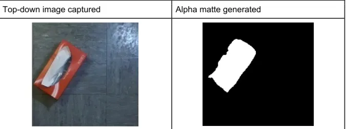
Table 6 shows an example of a top-down image captured of a tissue box and an alpha matte that has been created based on the height calculation by the stereo vision:
Top-down image captured Alpha matte generated
Table 6, RGB image taken by top-down stereo vision camera (left) and the alpha matte generated with the depth (right)
The strength of this alpha matte generating procedure is that, with this binary image (alpha matte), we are able to easily extract the bounding box of the object and no longer have to manually label the bounding box around the target object. Figure 19 shows how the bounding box can be derived based on the alpha matte without any manual labelling:
Figure 19, Bounding box generated solely based on the alpha matte of the image
In brief, with this alpha matte calculation from depth measurements, after RGB and depth images of target objects have been taken, the entire process of labelling the bounding box and data augmentation can be automated before leading up to training of the object detector model. This automation feature is extremely beneficial and crucial in making our project’s application scalable and customized to many users.
In this way, we need not spend excessive amounts of time to label and design an object detection model that works for every possible target object that exists. Instead, through this customization pipeline, the user needs only take a small number of images for each target object and wait for at most one to two days for training of the model prior to deployment. This model is then customized without the need for manual labelling of data and the user is able to experience an accurate object detector that has been customized for his / her household target objects.
Figure 20 shows an overview of this customization flow:
Figure 20, Flow diagram of the object detection customization
To make a fair evaluation, the model tested with automatic labelling by stereo vision was also evaluated with the mAP metric on real (non-augmented) images. As observed in table 6, as the alpha matte is not a perfect binary mapping of the tissue box, the bounding box is certainly not as perfect as a bounding box labelled manually. The mAP evaluated on the model with automatic labelling was at 70% which was certainly lower than a model trained with manually labeled images as shown in Table 2. However, as the object detector in our use-case continuously updates its detection, 70% on mAP metric was sufficient for our application. Furthermore, its benefit of scalability and privacy through automation and data augmentation from small dataset certainly outweigh its occasional misclassifications.
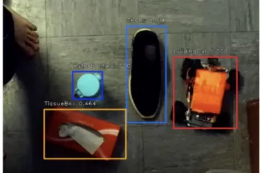
Figure 21 shows an example of the model’s performance on a real-life household setting:
Figure 21, Top down view of object detector trained with the customization pipeline
2.2.5.2 Customization for user (Voice recognition)
As discussed in the implementation section, the CNN method of voice recognition allows the model to be customized to adapt any language and speech. The procedure of customization will be designed and built as a user-friendly process during future development. Following is a description of the customization pipeline.
We will provide a function which allows the user to record any voice command phrasing of their choice. In this process, the user will be asked to record each command which does not exceed the duration of 2 seconds. After recording a multiple of 20 times, the system will enter a verification mode which will then ask the user to voice the command again. From this verification, the system will provide feedback on whether the command is accepted or rejected. If the system fails to recognize it, the user can record more voice samples until the system verifies and recognizes the command. The function of adding a voice command allows the user to create as many classes
as they want. When the command is created, it will be linked to a class in the object detection model. Figure 22 is an illustration of the described pipeline:
Figure 22, customization flow of the voice recognition function
3. Discussion
The various sub-sections under Methodology discuss the reason behind certain design choices, testing and incorporations of various components of our guiding car system. Ranging from object detection, voice recognition and path planning algorithms, the testing and the results of individual components could be observed in the preceding subsections.
As our project application is very user-oriented, subjective factors such as comfort and ease of use play a vital role in evaluating our system. Our initial plan was to gather a number of volunteers, blindfold them to simulate the challenges faced by the visually impaired and then evaluate our system’s performance based on their feedback in terms of comfort and ease of use. However, in view of the coronavirus situation, such testing could not be realised. As such, we have decided to display our system through visual means and thus we are currently working on a video demonstration of this project, which is therefore could not be showcased solely within this report.
4. References
[1]WHO, "World report on vision," World Health Organization, Department of Noncommunicable Diseases, 2018. Accessed on: Feb. 25, 2020. [Online]. Available : https://www.who.int/publications-detail/world-report-on-vision
[2]Opencv, “Computer Vision Annotation Tool (CVAT),” GitHub, 21-Feb-2020. [Online]. Available: https://github.com/opencv/cvat. [Accessed: 24-Feb-2020].
[3]Cartucho, “mAP (mean Average Precision),” GitHub, 15-May-2019. [Online]. Available: https://github.com/Cartucho/mAP. [Accessed: 24-Feb-2020].
[4]“ZED stereo camera,” STEREOLABS. [Online]. Available: https://www.stereolabs.com/zed/. [Accessed: 24-Feb-2020].
[5] “Depth Settings,” Stereolabs. [Online]. Available: https://www.stereolabs.com/docs/depth-sensing/depth-settings/. [Accessed: 24-Feb-2020].
[6] “LibROSA,” LibROSA. [Online]. Available: https://librosa.github.io/librosa/. [Accessed: 24-Feb-2020]. [7] D. Fox, W. Burgard and S. Thrun, "The dynamic window approach to collision avoidance," in IEEE