E L S E V I E R PII : S0141-0296(96)00079-X
Engineering Structures, Vol. 19, No. 6, pp. 465-475, 1997 © 1997 Elsevier Science Ltd Printed in Great Britain. All rights reserved 0141-0296/97 $17.00 + 0.00
Instantaneous control o f structures
with time-delay consideration
L. L. Chung
National Center for Research on Earthquake Engineering, National Taiwan University, Taipei, Taiwan, Republic of China
Y. P. Wang and C. C. Tung
Department of Civil Engineering, National Chiao Tung University, Hsinchu, Taiwan, Republic of China
(Received Janua~ 1996; revised version accepted June 1996)
A modified instantaneous control algorithm with time-delay con-
sideration for the active control of structures is developed in dis-
crete-time formulation. The shift-invariant feedback gain matrix is
obtained through an optimization process such that a prescribed
instantaneous quadratic performance index is minimized. The
effect of time-delay is taken into consideration by introducing a
compensation scheme where the feedback gain matrix for the ideal
control system is modified by the effective system matrix. It is
proved that the real control system with time-delay compensation
conserves the eigen-properties of the ideal control system with no
time-delay. In the presence of time-delay, the equation of motion
of the discrete-time control system remains a set of difference
equations which makes the evaluation of the control system simple
and straightforward. The feasibility of the proposed control algor-
ithm is verified numerically through eigenvalue, frequency-domain
and time-domain analyses by the tendon control of a structure.
With the proposed control algorithm, the control system is still
effective in spite of the presence of time-delay. © 1997 Elsevier
Science Ltd. All rights reserved.
Keywords: instantaneous control, time-delay control, active struc-
tural control, structural dynamics, earthquake engineering
1. Introduction
The impacts of control technology on different fields of engineering and the lives of mankind have been witnessed worldwide. In the civil engineering community, without exception, the topic of active control for dynamic response reduction originated by Yao ~ has become one of the domi- nant research fields since the 1970s 2-5. It is very encour- aging that the research area has now reached the stage of full-scale implementation 6 9. Meanwhile, further research efforts are still needed to thoroughly solve practical prob- lems in the implementation of control systems, such as the discrete-time nature of the control environment, time-delay effects, limited numbers of sensors and controllers, avail- ability of energy source, and reliability issues etc., before widespread applications of this novel technology become possible.
Various control strategies have been proposed. Among
them optimal control law is undoubtedly the most stringent and sound criteria for control design, by which the control signal is determined by minimizing a quadratic perform- ance index over a sufficiently long period of time ~°. The effectiveness of this algorithm for seismic response control of structures has been verified by Yang et al. ~j Yet, the complexity of solving the nonlinear system of Riccati equa- tions has discouraged most civil engineers from appreciat- ing this innovation. In an attempt to simplify the task of control design, Yang ~2 later proposed the instantaneous optimal control algorithm that avoids the trouble of solving the Riccati equation while conserving equivalent control efficiency.
Almost all the control systems are now incorporated with a digital computer for both online calculation and data acquisition. This motivates not only the discrete-time for- mulation of the aforementioned control algorithms but also the development of new digital control strategies t3. With
466
Instantaneous control of structures with time-delay consideration: L. L. Chung
et al the introduction of the digital computer, all information,including input control forces and output measurements, is basically discrete-time in nature. Therefore, it is more logi- cal and more realistic to formulate the control system in the discrete-time fashion.
Prior experimental studies indicated that time-delay results in degradation of the system performance and may lead to instability. Efforts for time-delay compensation have been made mainly through modification of the feed- back gains based on the principle of phase-shift H,t5 or through response prediction of the delayed states by either kinematic or dynamic approaches ~6. The former method needs to be performed in the phase space of modal coordi- nates. Unavoidable numerical errors would be accumulated, as the order of the system grows, during back and forth transformations of the states between physical and modal domains, and which would somehow abate the effect of compensation. The latter method uses either the truncated Taylor's expansion or the online solution of the system's equation for response forecasting. These approaches have been shown to be sensitive to the noise present in the sys- tem as reported in Reference 16. Other than the above men- tioned strategies, an interesting experimental study by Abdel-Mooty and Roorda w proposed a compensation scheme based on response sampling, curve fitting, and extrapolation for vertical vibration control of a simple bridge model. In their study the ideal feedback gains were used and the lagged responses were predicted through a filtering process. Only single mode control was considered in the tests and no spillover effect was observed for the uncontrolled modes. In the presence of time-delay, the gov- erning equation of the active structural control system becomes a differential-difference equation instead of the original differential equation. The analytical method for the evaluation of the stability of the control system is limited to single-degree-of-freedom structures t~.
In this paper, a modified instantaneous control algorithm is developed for the dynamic response control of structures. The proposed algorithm is derived based on the concept of instantaneous controP -~ under a discrete-time framework in which first-order discretization of the continuous-time func- tion is considered. The effect of time-delay is taken into consideration and a feedback compensation scheme is pre- sented by simply modifying the gain matrix with the effec- tive system matrix. Unlike the continuous-time system, the effects of time-delay for the discrete-time control system can be easily accommodated in the difference equation and thereby assessed in a more elegant fashion, for a broader category of structures. It is proved through eigenvalue analysis that the real control system with time-delay com- pensation conserves the properties of the ideal control sys- tem with no time-delay. The effectiveness of the proposed control law with time-delay compensation is confirmed through numerical simulations.
2 . C o n t r o l a l g o r i t h m
When an n-degree-of-freedom (DOF) discrete-parameter structural system is subjected to environmental loads w(t) and counteracted by control forces u(t), its governing e q u ation can be taken as
the n x n mass, damping and stiffness matrix, respectively, B is the n x p location matrix of control forces, and E is the n × q location matrix of external loads. Represented in state-space form, the second-order differential equation ( 1 ) is changed to a first-order differential equation as
z(t) = A , z ( t ) + B , u ( t ) + E , w ( t ) (2) where
F 1
z(t) = [ x ( t ) l is the 2n x 1 state vector
Lx(t)A
I °
' ]
A, = - M ]K - M ]C is t h e 2 n x 2 n system matrix
. = [ : . ]
i,
control matr,
i,t e lo=matrix
The control system described by the state equation (2) is linear and time-invariant so that its solution takes the form
~
t ~ = ~ c A ( t 2 - r ) Z(t2) eA'<'2-qlz(tl) + [B,u('r) J / I + E~.w(r)]d'r (3)where t] and t 2 are any two time instants. During real-time control, suppose all information for the online calculation of control forces is sampled with period At and the control forces are calculated once every sampling period. Between two consecutive sampling instants, ( k - 1)At and kAt, the only available information about the control forces is
u ( ( k - 1 )At) and u ( k A t ) and the only available information
about the external loads is w ( ( k - 1 )At) and w(kAt). There- fore, it is reasonable to assume that the control forces and external loads are linear between two consecutive sampling instants as z - ( k - 1 ) A t u [ k A t ] , k A t - z u [ ( k - 1)At] + (4a) u ( r ) - At At ( k - 1 ) A t ~ z < kAt k A t - "c w ( r ) = At w [ ( k - 1)At] + T - ( k - !)Atw[kAt] ' (4b) At ( k - l ) A t ~ T < k A t
When t~ = (k - 1)At, t2 = kAt, z[k] = z(kAt), u[k] = u ( k A t ) and w[k] = w ( k A t ) are assigned, from equation (3), the analytical solution to the state equation (2) is a difference equation as
z [ k ] = A z [ k - 1 ] + B o u [ k - 1 ] + n l U [ k ]
+ Eow[k - 1 ] + E l W [ k ]
(5)
M £ ( t ) + Ck(t) + K x ( t ) = B u ( t ) + E w ( t ) ( 1 ) where
Instantaneous control o f structures with time-delay consideration: L. L. Chung et al ~ _ • x 3 ( t ) 4 6 7 __ ~ . X 2 ( t ) Xl (t) w(t) Figure I 3DOF model structure with control device
[
,2
]
Bo = AsIA + A ? S ( l - A ) B,. is the 2 n x p discrete-
time control matrix of the previous time step
Bt = - A s ~ + A ? ~ ( A - I ) B,. is the 2 n x p discrete-
time control matrix of the current time step
Eo = A,.]A + A ? S ( I - A ) E~. is the 2n x q discrete-
time load matrix of the previous time step
[ 1 2 ]
Et = -A2 ~ + A ? 2 ( A - I ) Ec is the 2n × q discrete- time load matrix of the current time step
As a whole, it is more logical and more realistic for the structural control system to be modelled in a discrete- time fashion.
The current active control forces are found such that the quadratic objective function
J[k] = zr[k]Qz[k] + ur[k]Ru[k] (6) is minimized. In the above equation, Q is the 2n × 2n sym- metric positive semidefinite weighting matrix for the responses, R is the p × p symmetric positive definite weighting matrix for the input control forces, and superscript T denotes transposition of a matrix.
With instantaneous control law, the optimization prob- lem is: searching for the optimal control forces u[k] that
minimize the performance index J[k] in equation (6) sub-
ject to the constraint of the discrete-time state equation (5). Incorporated with the constraint equation (5), the Lagrang- ian J ' can be defined as
f = zV[k]Qz[k] + uT[k]Ru[k] + Ar[k]{Az[k - 1] + B o u [ k - 1] + B j u [ k ] + E o w [ k - 1] +E]w[k] (7)
- z[k]}
where A[k] is the 2n × 1 Lagrangian multiplier vector. :>
Because the performance index is quadratic, and Q and R are positive semidefinite and positive definite matrices, respectively, the necessary and sufficient conditions for the minimization of the Lagrangian J ' are
oJ'[k] Oh[k] ay'[k] az[ k ] aJ'[k] au[k] - A z [ k - 1] + B o u [ k - 1] + B~u[k] (8) + E o w [ k - 1] +E~w[k] - z [ k ] = 0 - 2Qz[k] - A[k] = 0 (9) - 2Ru[k] + B~A[k] = 0 (10)
From equation (9), the Lagrangian multipliers A[k] are lin- early related with the states as
h[k] = 2Qz[k] ( 11 )
From equation (10), the control forces are linearly related with the Lagrangian multipliers A[k] as
1 i T
u[k] = - 2 R - B~A[k] (12)
By substituting equation (11 ) into (12), the control forces are in turn linearly related to the states as
u[ k ] = - R - ' BrQz[ k ] = Gz[ k ] (13)
where G = -R-tB~Q is the p x 2n feedback gain matrix
which is a constant matrix. The control forces u[k] are sim-
ply generated from the structural states z[k] multiplied by
the precalculated constant feedback gain matrix G.
3. T i m e - d e l a y c o m p e n s a t i o n
The discrete-time control system described by the state equ- ation (5) has been idealized where the control forces u[k]
468
Instantaneous control of structures with time-delay consideration: L. L. Chung
et alTable 1 System parameters of 3DOF control system
System parameter Parameter value
(1) (2) Mass matrix, M (kg) [981 0 981 0 Stiffness matrix, K (N/m) [2741 700 /
-1 641 600
L369 100 Damping matrix, C (N-s/m) [382.8 -57.3/
57.3 456.9 L61.7 -2.6 Modal frequencies, f(Hz) 12"24 116.8o /
L11.49]Modal damping ratios, ~'(% ) [1.611
/ /
/o.39/
L0.36J
Control force location matrix, B
[il
External load location matrix, E [-981]
/ /
F981 /
L-981J
Tendon stiffness, kc (N/m) 372 100
Tendon inclination, a (°) 36
Response weighting matrix, O [O K
O]
Control weighting matrix, R 13
16kccos%~
Control weighting factor, /3 0.25
i81]
-1 641 600 3022200 -1 624800 61.71
369100 1 1624800 / 1333600 Jcan be applied to the structure simultaneously as the states
z[k] are measured. In practice, time has to be consumed during data conditioning, online calculation and control force application. Taking time-delay into consideration, the state equation (5) becomes
z[k] = A z [ k -
1]
+ B o u [ k - 1 -1]
+ B ~ u [ k - l ] + E o w [ k - 1] + Etw[k](14)
Following the optimization procedures stated in the pre- vious section, the necessary and sufficient conditions for the minimization of the performance index (15) are
aJ'[k]
M ' l k ]
where 1 is the number of delayed time steps. The appli-
8z[k]
cation of the control forces
u[k]lags the measurement of
M'[k]
the state variables
z[k]by
lAt.With time-delay, the instant
performance index (equation (6)) becomes
O u [ k - I ]= A z [ k - 1] + B o u [ k - l - 11 + B ~ u [ k - l ] (16)
+ E o w [ k - 1] + E~w[k] - z[k] = 0
= 2Qz[k] - A[k] = 0 (17)
= 2 R u [ k - l] + B~A[k] = 0
(18)
J[k] = zT[k]Qz[k] + u T [ k - l ] R u [ k - I] (15)In the presence of time-delay, the optimization problem is converted to the minimization of the performance index (15) subject to the constraint of the state equation (14).
From equations (17) and (18), the time-delay control forces
u [ k - 1 ] "are linearly related to the current state variables z[k]by
Instantaneous control o f structures with time-delay consideration: L. L. Chung e t al 4 6 9
40.00
30.00
w - , v20.00 - -
10.00 1
0.00
J
i . . . . o . O ° " * ' ' i l l I . . . ' I ' I '0.00
4.00
8.00
f ( H z )
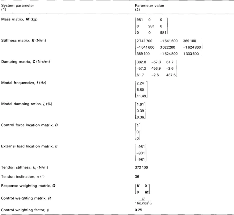
Figure 2 Top-floor absolute acceleration frequency response function at /= 0
l = O C o n t r o l l e d . . . U n c o n t r o l l e d
i
• " t lI
12.oo
16.00
Table 2 Control effect for 3DOF structure
Number of delayed time steps
Modal frequencies, f(Hz)
Damping ratios, (%)
No delay Time delay No delay Time delay
consideration compensation consideration compensation
/ = 0 2.407 ] 10.522 / 7.929 J 16.2 1 8.774 t 63.75J
,:2
F14.~1l
[2.4071
[_,2.8~]
rio.21
/2.46~/
/10.~22/
/13.287/
/8.774/
L 9.387 J L 7.929 J L 5.01 J L63.75J,=4
r~o~]
i~4o~1
p~141
r lOCi
p964~ /
/10~22/
/-9.245/
/8.774/
L 2.502 J L 7.929 J L10.523J L63.75J/1°.625/
/l°.522/
/-°.386 /
/8.774/
L 2.528 J L 9.161 J L 7.95 J L23.123//15496/
/10522/
t-1596/
r8774f
L 2.547 J L 8,698 J L 5,473 J L21.168JThe control forces u [ k - 1 ] depend on the state variables
z[k] which are not available at the time step [k - l]. Conse- quently, the control law represented by equation (19) can- not be implemented. Instead of the current state variables
z[k], the time-delay state variables should be used for the online calculation o f the time-delay control forces. In order to evaluate the stability of the control system, the corre- sponding autonomous system o f the time-delay state equ- ation (14) is considered. After substituting equation (19) into the time-delay state equation (14), the current state
variables z[k] and the previous state variables z [ k - 1] are related by
z[k] = ( l + B ] R ' W f Q ) - ' ( A - BoR ' B ~ Q ) z [ k - 1 ] (20)
= Sz[k - 1 ]
where S is the 2n x 2n transition matrix
4 7 0 Instantaneous control o f structures with time-delay consideration: L. L. Chung e t al Figure 3 Figure 4 4 0 . 0 0 3 0 . 0 0 ,..., 2 0 . 0 0 "I- D 1 0 . 0 0 0 . 0 0
q
t
I
iiti
• t " ° °°"it
L
" - . | l = 2Tim e-delay compensation Uncontrolled
. . . 4 1 |
' I ' I
0 . 0 0 4 . 0 0 8 . 0 0 1 2 . 0 0 1 6 . 0 0
f ( H z ) Top-floor absolute acceleration frequency response function at /= 2
m A .1- 4 0 . 0 0 3 0 . 0 0 2 0 . 0 0 1 0 . 0 0 0 . 0 0
t
i i{ i l-
ii
- ~
ii
t
/t
A
- i i t - . ' I ' I ' [ 0 . 0 0 4 . 0 0 8 . 0 0 1 2 . 0 0 f ( H z ) Top-floor absolute acceleration frequency response function at I= 4I=4
Time-delay compensation
Uncontrolled
1 6 . 0 0
= ( I - B i G ) I ( A + B o G )
By applying the relation in the above equation repeatedly to equation (19), the time-delay control forces u [ k - l] can be generated from the time-delay state variables z [ k - l] as u [ k - l] = G S ~ z [ k - 1] = G , z [ k - l] ( 2 2 )
where G , = G S t is the p x 2n compensated feedback gain matrix. After time-delay compensation, the control law rep- resented by equation (21) can now be implemented.
4. E v a l u a t i o n o f c o n t r o l s y s t e m
In eigenvalue analysis, the enhancement of the control sys- tem is indicated by the system paralneters such as natural frequencies and damping ratios extracted from the eigenval-
ues of the system matrix. The ith eigenvalue ,/i can be expressed as
m
'Yi = Pi et°~ = e Zi%AreJ'°i~'l ¢iAI ( 2 3 )
where j = x/-1, ~oi is the ith effective natural frequency and ~'~ is the ith damping ratio. Therefore, the ith effective natu- ral frequency and damping ratio can be extracted from the ith eigenvalue of the control system as
1
~o, = A t ~/(lnp')2 + 0,.2 ( 2 4 )
l n p i
~'i = - x/(lnpi)2 + 07 (25)
Instantaneous control o f structures with time-delay consideration: L. L. Chung et al 471 Figure 5 4 0 . 0 0 m v "I- D 3 0 . 0 0 - - 2 0 . 0 0 1 0 . 0 0 0 . 0 0 ..'i
-
il
J
ii
. . . , 1 ° " i 0 . 0 0 4 . 0 0 1=6 T i m e - d e l a y c o m p e n s a t i o n U n c o n t r o l l e d ,tA
i I ' I 8 . 0 0 1 2 . 0 0 f ( H z ) T o p - f l o o r a b s o l u t e a c c e l e r a t i o n f r e q u e n c y r e s p o n s e f u n c t i o n at / = 6 t 1 6 . 0 0 Figure 6 "1- 4 0 . 0 0 3 0 . 0 0 - - 2 0 . 0 0 - - 1 0 . 0 0 - - 0 . 0 0 i ' I 0 . 0 0 4 . 0 0 1=8 T i m e-delay c o m p e n s a t i o nU neon tro lied
A
i "'';° "'%= o°' • r "i ... ' . . . ? ' 8 . 0 0 1 2 . 0 0 f ( H z ) T o p - f l o o r a b s o l u t e a c c e l e r a t i o n f r e q u e n c y r e s p o n s e f u n c t i o n at / = 8 1 6 . 0 0ith mode is stable and convergent. When Oi > 1, the damp- ing ratio ~'i is negative so that the ith mode is unstable and divergent. Therefore, if all the eigenvalues are located within the unit circle of the complex plane, the control sys- tem is stable and convergent. The stability criterion for a discrete-time system is different from that for a continuous- time system ~9.
In the uncontrolled case, the state equation (5) becomes
z[k] = A z [ k - 1] + E o w [ k - I] + E~w[k] (26) The eigenproperties of the structure can be extracted from the system matrix A. By substituting the control law equ- ation (13) into the state equation (5), the effective state equation for the ideal control system where time-delay does not exist is
z[k] = A z [ k - 1] + B o G z [ k - 1] + B,Gz[k] (27)
+ E o w [ k - 1] + E~w[k]
From the above equation, the characteristic equation for the ideal control system is
It
- A T - 1 - B o G y - I -BIGI
= 0 (28) where I.I denotes the determinant of a matrix. The eigenpro- blem stated in the above characteristic equation is equival- ent to solving for the eigenvalues of the effective system matrixA" = ( I - BjG)-I(A + BoG) = S (29) By substituting the control equation (21) into the state equ- ation (14), the effective state equation for the real system where time-delay does exist is
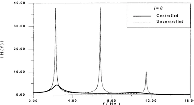
472 Instantaneous control o f structures with time-delay consideration: L. L. Chung et al 0 . 0 8 0 . 0 4 - - E v 0 . 0 0 - - X - 0 . 0 4 - - - 0 . 0 8 0 . 0 0
i ii ii ill lit
,,.
' Jiiiiii!ii i
l=O C o n t r o l l e d I I . . . U n c o n t r o l l e d I I ! ' l ' I 4 . 0 0 8 . 0 0 1 2 . 0 0 1 6 . 0 0 t ( s e c )Figure 7 Top-floor relative displacement under El Centro earthquake at / = 0
2 0 . 0 0 0 . 0 8 E X 0 . 0 4 - - 0 . 0 0 - - - 0 . 0 4 - - [ 1=2 T i m e - d e l a y c o r n p c n s a t i o n U n c o n t r o l l e d • '-J t , ,, .,.
!ii ii ii ii
..,. i.,,.
[: :: :, :; :: -iVVI~ilV
i - 0 . 0 8 ' I r I ' I ' [ o . o o 4 . 0 0 8 . 0 0 1 2 . o o 1 6 . o o t ( s e c )Figure8 Top-floor relative displacement under El Centro earthquake at / = 2
2 0 . 0 0
z [ k ] = A z [ k - 1 ] + B o G , z [ k - I - 1 ] + B i G , z [ k - 1] + E o w [ k - l ] + E i w [ k ]
(30) sation conserves the eigen-properties of the ideal control system with no time-delay.
From the above equation, the characteristic equation for the real control system is
I I - A y -] - B o G ( A ' ) / y -/-' - B I G ( A ' ) / T / I (31) = [F(y)l = 0
It is found that the effective system matrix A ' for the ideal control system satisfies the characteristic equation for the real control system
F ( A ' ) = 0 (32)
Therefore, the real control system with time-delay compen-
5. N u m e r i c a l verifications
The feasibility of the proposed control algorithm is verified numerically through the tendon control system of a three- degree-of-freedom (3DOF) structure. The dynamic charac- teristics of the model structure shown in F i g u r e 1 have been studied thoroughly ~5. The three-storey structure is subjected to seismic motion and counteracted by the tendon control device implemented on the first floor. Relevant parameters of the control system are listed in T a b l e 1. The control effectiveness is evaluated through eigenvalue, frequency- domain and time-domain analyses. In the eigenvalue analy- sis, the enhancement of the control system is indicated by the system parameters extracted from the eigenvalues of
I n s t a n t a n e o u s c o n t r o l o f structures w i t h t i m e - d e l a y consideration: L. L. C h u n g e t al 4 7 3 E , , . . , , x 0 . 0 8 0 . 0 4 0 . 0 0 - 0 . 0 4 - - - 0 . 0 8
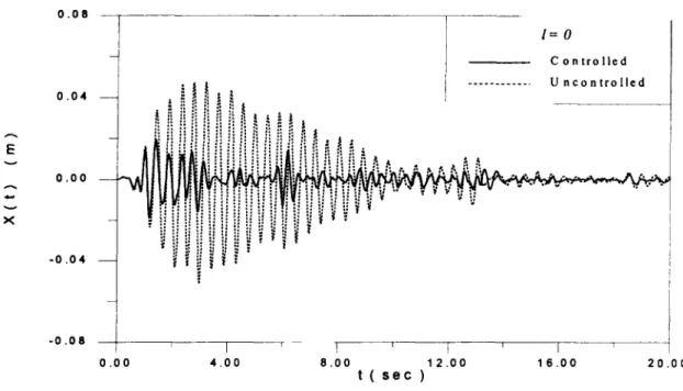
i = 4
T i m e - d e l a y c o m p e n s a t i o n . . . U n c o n t r o l l e d• --- t A t t
,. n
ilA.,
": "~ i] j{ ,:~ :' "1 .:l |: ~:..": q i" :': :~ "z :.'.' iiiiiii~i
. . s . ' ~ i i i | "J'J s [iii !i i~ ii - ~ , ...,. ' I ' I ' I ' I ' 0 . 0 0 4 . 0 0 8 . 0 0 1 2 . 0 0 1 6 . 0 0 2 0 . 0 0 t ( s e c )Figure 9 Top-floor relative displacement under El Centro earthquake at /= 4
E v A v 0 . 0 8 0 . 0 4 I 0 . 0 0 \ - 0 . 0 4 - 0 . 0 8 I = 6 T i m c - d e l a y c o m p e n s a t i o n U n c o n t r o l l e d
, !t t ,.,
.- ~,ii !i ii il !i • !. i t
.1. " !! ]i ~i i" !~ fi !" i! il ii ~i t• ,
'I ~"ii i~ il ~: "i ~ii il ii ~i !i A ,,.,
,. ,.I
! ' 1 ' I ' I ' I 0 . 0 0 4 . 0 0 8 . 0 0 1 2 . 0 0 1 6 . 0 0 2 0 . 0 0 t ( s e c )Figure 10 Top-floor relative displacement under El Centro earthquake at /= 6
the effective system matrix of the control system. In the frequency-domain analysis, the degree of vibration sup- pression is shown by the peaks of the frequency response function of the control system. Finally, in the time-domain analysis, the reduction of the structural response is demon- strated by subjecting the structure to the 1940 E1 Centro earthquake (N-S component).
The control effects from the eigenvalue analysis of the control system are listed in
Table 2
while the results from the frequency-domain and time-domain analyses are shownin
Figures 2-6
and7-11,
respectively. The states of thestructure are measured with a sampling period of At = 0.01 s. As the number of delayed time steps 1 varies, its influences on the different control strategies are dis- cussed below.
(1) When l = 0, it is the ideal control system where no time-delay exists. Under the action of the control force,
(2)
the natural frequencies are changed from 2.24 Hz, 6 . 8 0 H z and l l . 4 9 H z to 2.41 Hz, 7 . 9 3 H z and 10.52Hz, respectively, and the damping ratios are increased greatly from 1.61%, 0.39% and 0.16% to 16.20%, 63.75% and 8.77%, respectively,
(Table 2).
The effectiveness of this control case is obvious from the frequency-domain and time-domain analyses
(Figures 2
and 7). In fact, this case possesses the bestcontrol result but it is not realistic since time-delay is unavoidable
When l = 2, the time-delay is 20 ms. If time-delay is neglected, the control system becomes unstable as indi- cated by the negative damping ratio
(Table 2).
The frequency response function is not available since the structural response blows up and no steady-state response can be achieved(Figure 8).
If time-delay is considered, the control system remains stable. The sys-474 I n s t a n t a n e o u s c o n t r o l o f s t r u c t u r e s w i t h t i m e - d e l a y c o n s i d e r a t i o n : L. L. C h u n g et al Figure 11 E v 0 . 0 8
t
0 . 0 4 - - J 0 . 0 0 - 0 . 0 4 - 0 . 0 8 1 = 8 T i m e - d e l a y c o m p e n s a t i o n • ! ! . . . U n c o n t r o l l e d "~ ~ ... ~ ~ i ii i i i i l i ii.;,, r.,. ,~ ~ i~ i~ :" il i! ii f i i i i~ r =" ii " ~ ~. . i , l , * 0 • i = , l ; l ; ~ . ; . ; _. ~ t~ • & • ~ ~ ,', =~ ; | " ' I ' ' | ' l l I | I ° I | ° ; , ' ; ' ; ' * . ,~ . 0 . 0 0 ' r ' , ' I ' i r 4 . 0 0 6 . 0 0 1 2 . 0 0 1 6 . 0 0 2 0 . 0 0 t ( sec )Top-floor relative displacement under El Centro earthquake at /= 8
tem parameters, modal frequencies and damping ratios, extracted from the three eigenvalues with the largest modulus pi's are identical to those from the ideal con- trol system
(Table 2).
In other words, the parameters of the three lowest modes for the real control system with time-delay compensation are identical to those for the ideal control system with no time-delay. The con- trol effectiveness of the real system is close to that of the ideal system as observed from the frequency- domain and time-domain analyses(Figures 3
and 8) (3) When l = 4 , the time-delay is increased to 40 ms. Iftime-delay is neglected, the control system is unstable
(Table 2).
If time-delay is considered, the control sys-tem remains stable and the parameters of the three low- est modes are identical to those of the ideal control system. The control effectiveness of this case is very close to the case of / -- 2 as observed from frequency- domain and time-domain analyses
(Figures 4
and 9) (4) When l = 6, the time-delay is increased to 60 ms. Iftime-delay is neglected, the control system is unstable
(Table 2).
If time-delay is considered, the control sys-tem remains stable. In total there are 21 pairs of com- plex conjugate eigenvalues and three of the pairs are identical to those of the ideal system but only two out of the three pairs remain in the three lowest modes
(Table 2).
The control effectiveness of this case is veryclose to that of l = 4 as observed from the frequency- domain and time-domain analyses
(Figures 5
and10)
(5) When l : 8, the time-delay is further increased to 80 ms. If time-delay is neglected, the control system is unstable
(Table 2).
If time-delay is considered, the control system remains stable. In total there are 27 pairs of complex conjugate eigenvalues and three of the pairs are identical to those of the ideal system but only two out of the three pairs remain in the three low- est modes(Table 2).
The control effectiveness of this case is very close to that of 1 = 6 as observed from the frequency-domain and time-domain analyses(Figures
6 and
11)
6. Conclusions
A modified instantaneous control algorithm for the active control of structures is developed in discrete-time formu- lation which is very efficient when a digital computer is introduced for the real-time calculation of control forces. In real-time control, time is needed for data acquisition, data conditioning, calculation and applications of control forces. If time-delay is neglected, the control system is sus- ceptible to dynamic instability. Therefore, it is better not to put any control action into the structural system before the time-delay is analysed and tackled properly. In this paper, a feedback compensation scheme is developed by simply modifying the feedback gain matrix of the ideal con- trol system with the effective system matrix. It is also proved that the real control system with time-delay com- pensation conserves the eigen-properties of the ideal con- trol system with no time-delay. In the presence of time- delay, the equation of motion of the discrete-time control system remains a set of difference equations which makes the eigenvalue analysis of the control system simple and straightforward. It is one of the great advantages of dis- crete-time formulation. The feasibility of the proposed algorithm is verified numerically through eigenvalue, fre- quency-domain and time-domain analyses. The control forces are simply generated from the time-delay states mul- tiplied by the precalculated and shift-variant modified feed- back gain. Such simple online calculation of the control forces makes the proposed control algorithm favourable for real implementation. With the proposed control algorithm, the control system is still effective in spite of the presence of time-delay.
References
1 Yao, J. T. P. ' C o n c e p t o f structural c o n t r o l ' , J. Struct. Div., ASCE
1972, 98, 1 5 6 7 - 1 5 7 4
2 R e i n h o r n , A. M. and Manolis, G. D. ' C u r r e n t state o f k n o w l e d g e on structural c o n t r o l ' , Shock Vibr. Digest 1985, 17. 3 5 - 4 1
Instantaneous control of structures with time-delay consideration: L. L. Chung et al 475
engineering structures', J. Probabilistic Engng Mech. 1988, 3,
179-188
4 Soong, T. T. "Active structural control in civil engineering', Engng. Struct. 1988, 10, 74-84
5 Soong, T. T. Active structural control: theory and practice, Wiley,
New York, 1990
6 Soong, T. T., Reinhorn, A. M., Wang, Y. P. and Lin, R. C. 'Full- scale implementation of active control. I: Design and simulation', J.
Struct. Engng, ASCE 1991, 117, 3516-3536
7 Kobori, T., Koshika, N., Yamada, K. and lkeda, Y. 'Seismic- response-controlled structure with active mass driver system. Part l: Design', Earthquake Engng Struct. Dyn. 1991, 20, 133-149
8 Kobori, T., Koshika, N., Yamada, K. and Ikeda, Y. 'Seismic- response-controlled structure with active mass driver system. Part 2: Verification', Earthquake Engng Struct. Dyn. 1991, 20, 151-166
9 Reinhorn, A. M., Soong, T. T., Riley, M. A., Lin, R. C., Aizawa, S. and Higashino, M. 'Full-scale implementation of active control. II: Installation and performance', J. Struct. Engng, ASCE 1993, 119,
1935 1960
10 Sage, A. P. and White, C. C. Optimum systems control, Prentice-
Hall, Englewood Cliffs, NJ, 1977
1 I Yang, J. N., Akbarpour, A. and Ghaemmaghmi, P. 'Optimal control algorithms for earthquake excited building structures', Structural
Control, Proc., 2nd Int. Symp. on Struct. Control, (Ed.) H. H. E.
Leipholz, Nijhoff, Amsterdam, The Netherlands, 1985, pp. 748-761 12 Yang, J. N., Akbarpour, A. and Ghaemmaghmi, P. 'New optimal control algorithms for structural control', J. Engng Mech., ASCE
1987, 113, 1369-1386
13 Rodellar, J., Barbat, A. H., and Martin-Sanchez, J. M. 'Predictive control of structures', J. Engng Mech., ASCE 1987, 113, 797-812
14 Chung, L. L., Reinhorn, A. M. and Soong, T. T. 'Experiments on active control of seismic structures', J. Engng Mech., ASCE 1988,
114, 241-256
15 Chung, L. L., Lin, R. C., Soong, T. T. and Reinhorn, A. M. 'Exper- imental study of active control for MDOF seismic structures', J.
Engng Mech., ASCE 1989, 115, 1609-1627
16 McGreevy, S., Soong, T. T. and Reinhorn, A. M. 'An experimental study of time delay compensation in active structural control', Proc. 6th Intl. Modal Analysis Conf. Society jbr Experimental Mechanics,
Kissimmee, FL, 1988, pp. 733-739
17 AbdeI-Mooty, M. and Roorda, J. 'Time-delay compensation in active damping of structures', J. Engng Mech., ASCE 1991, 117, 2549-2570
18 Zhang, L., Yang, C. Y., Chajes, M. J. and Cheng, H.-D. 'Stability of active-tendon structural control with time delay', J. Engng Mech., ASCE 1993, 119, 1017-1024