Available online at www.sciencedirect.com
Synthetic Metals 158 (2008) 25–28
Electron mobility and electroluminescence efficiency
of blue conjugated polymers
Chia-Ming Yang
a, Hua-Hsien Liao
a, Sheng-Fu Horng
a, Hsin-Fei Meng
b,∗,
Shin-Rong Tseng
b, Chain-Shu Hsu
caDepartment of Electric Engineering, National Tsing Hua University, Hsinchu 300, Taiwan, Republic of China bInstitute of Physics, National Chiao Tung University, Hsinchu 300, Taiwan, Republic of China
cDepartment of Applied Chemistry, National Chiao Tung University,
Hsinchu 300, Taiwan, Republic of China
Received 17 July 2007; received in revised form 16 November 2007; accepted 21 November 2007 Available online 14 January 2008
Abstract
We study systematically the underlying property which determines the electroluminescence efficiency of blue polymers based on polyfluorene and its copolymers. The photoluminescence efficiency is high (40–50%) for all the selected polymers, but the electroluminescence efficiency varies in a wide range. The hole mobility is measured by transient electroluminescence. The electron mobility is obtained from the current in electron-only device using space-charge-limited current equation. All polymers share roughly the same results, whereas electron mobility is the critical factor for electroluminescence. In general, low efficiency results from the low electron mobility.
© 2007 Elsevier B.V. All rights reserved.
Keywords: Polymer-LED; PFO(poly-fluorene); TR-EL; Electron mobility
Solution-processed polymer light-emitting diode (PLED) have a great potential for many low-cost and large area dis-play applications, for example in the emissive pixels or backing light of the liquid crystal display. In order to achieve full-color blue light is the most critical. Green and red light can be obtained from blue light either using color converter exter-nally or using dopants in the polymer host interexter-nally. So far, the red and green PLED have high efficiency, while the blue PLED is falling behind. Furthermore, for the blue polymer with relatively high efficiency, like LUMATION* BP105 developed by the Dow Chemical Company, the chemical structure is not available and the material has to meet stringent conditions and is difficult to synthesize in large scale with low cost. For other blue polymers based on polyfluorene and copolymers with known chemical structure and easier synthesis, the PLED efficiency is much lower. It is therefore vital to understand the microscopic properties which determines the efficiency and reveal the cor-relation between these properties and the chemical structures.
∗Corresponding author. Tel: +886 5731955.
E-mail address:[email protected](H.-F. Meng).
Interestingly, the photoluminescence (PL) quantum efficiency is high for some blue polymers with very poor PLED efficiency. High PL efficiency means the excitons are easy to emit light, but the performance of LED is limited also by the charge transport and exciton formation. For all the blue polymers the ionization potential (IP) is around 5.8 eV. With similar energy gap, the elec-tron affinity (EA) is expected to be similar to one another and located around 2.8 eV. Charge injection from the lower work function cathode is not expected to be the main factor to deter-mine the efficiency. Charge carrier mobility is therefore likely to underlie the observed difference in efficiency. Surprisingly, even through the carrier mobility of poly(p-phenylene vinylene) (PPV) derivatives have been studied extensively[1,2], no such study was performed for polyfluorene especially for the electron part.
In this paper, we compare the hole as well as the electron mobility for a selection of blue polymers based on polyfluo-rene (PF) and copolymers. The hole mobility is measured by the transient electroluminescence (EL) method[4–6], while the electron mobility by the space-charge-limited current (SCLC) fitting. It turns out that the hole mobility of all the polymers are about the same, but the electron mobility differs by several
0379-6779/$ – see front matter © 2007 Elsevier B.V. All rights reserved. doi:10.1016/j.synthmet.2007.11.006
26 C.-M. Yang et al. / Synthetic Metals 158 (2008) 25–28
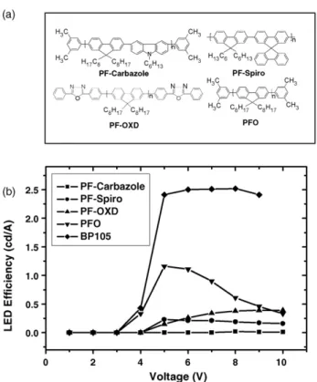
Fig. 1. (a) The chemical structure of four PF-derivatives. (b) The EL efficiency of the PLED as function of driving voltage.
orders of magnitude. More importantly, there is a direct cor-relation between the electron mobility and the LED efficiency. Good electron transport is therefore identified as the single most important property for a high-efficiency blue PLED.
Four PF derivatives are studied: dioctylfluorenyl-2,7-diyl) end capped-with dimethylphenyl (PFO), poly(9,9-dioctylfluorenyl-2,7-diyl) end capped-with 2,5-diphenyl-1,2,4-oxadiazole (PF-OXD), dihexylfluorenyl-2,7-diyl)-alt-co-(9,9’-spiro-bifluorene-2,7-diyl)] (PF-Spiro), and poly[(9,9-dioctylfluorenyl-2,7-diyl)-alt-co-(9-hexyl-3,6-carbazole)] end capped-with dimethylphenyl (PF-Carbazole). The materials are purchased from American Dye Source. The chemical structures are shown inFig. 1(a). BP105 from the Dow Chemical Com-pany with unknown structure is also inducted for comparison. The polymers are dissolved in toulene and LEDs are fabricated on indium tin oxide (ITO)-coated glass substrate. The 50 nm hole injection layer poly(3,4-ethylene dioxythiophene) doped by poly(styrene sulphonate) (PEDOT:PSS) is spin-coated. On top of that the PF derivatives are spin-coated as the emissive layer with thickness of 100 nm. The cathode is calcium (35 nm)
Fig. 2. The response signal is the PFO LED emission at 8 V square pulse, and the synchronized signal is the applied pulse. The device is ITO/PEDOT/PFO/Ca/Al. The delay timet1is indicated in the insert and the detailed description are shown
in Ref.[3].
capped with aluminum (100 nm). The active area is 4 mm2. The LED characteristics are shown in Fig. 1(b). PL efficiency is measured for thin film spin-coated on the glass substrate. The photo-excitation source is 405 nm laser, and the fluorescence is collected by an integration sphere to obtain the absolute PL quan-tum efficiency. The PL and maximal EL efficiency are shown inTable 1. The remarkable feature is that while the PL efficien-cies are all around 40%–50%, the EL current efficiency differ by as large as 100 times. They can be roughly grouped as poor (PF-Carbazole), intermediate (PF-Spiro, PF-OXD, PFO), and good (BP105). Mobility measurement is performed to reveal the origin of such difference.
The hole mobility is measured by the transient EL under elec-tric pulse. As a square voltage pulse is applied to the LED, there is a delay between the pulse and the rise of the light emission because the carriers need to move across the emissive layer to recombine. The delay is mainly determined by the time which the faster carriers take to move across the whole thickness. Hole is known to be the faster carrier in PF derivatives[3]. The EL delay can be therefore used to get the hole drift velocity and consequently the mobility with known electric field. The LED is driven by a function generator (Agilent 33220A) with 35 ns rise time. The repetition rate is 50 KHz, and the driving voltage operates from 5 to 10 V. The temporal evolution of the light out-put is measured by a photomultiplier tube (Hamamatsu R3256) with 31 ns delay time and 3.4 ns rise time. The overall response time of the instrument is 20–30 ns. The response waveform of
Table 1
The PL and EL efficiency of four PF-derivatives and BP105 are compared
Polymer PF-Carbazole PF-Spiro PF-OXD PFO BP105
PL efficiency (%) 36.8 34.6 56.2 45.0 40.5
Maximum EL efficiency (cd/A) 0.02 0.23 0.40 1.16 2.52
EL EQE (%) 0.01 0.16 0.38 0.82 1.50
ELλmax(nm) 425 425 432 435 470
EQE is external quantum efficiency.λmaxis the peak wavelength of EL spectrum. The LED structure is ITO/PEDOT(50 nm)/PF(100 nm)/LiF(2 nm)/Ca(35 nm)/
C.-M. Yang et al. / Synthetic Metals 158 (2008) 25–28 27
Fig. 3. The hole mobility versus driving voltage of four PF-derivatives.
the PLED output and the synchronized pulse signal are shown inFig. 2.t1is the rise time and the hole mobility μhis given
byμh= L2/t1(V − Vbi). L is the emissive layer thickness, V
is the driving voltage, and Vbi=2.2 V is the build-in voltage
(the work function difference between two electrodes). The rise timet1shown decreases as the voltage increases as expected.
The resulting hole mobility is shown inFig. 3. The mobility increases slightly with the driving voltage and saturates at the high electric field. The hole mobility of PFO is similar to the earlier reports[3,6]. The hole mobility of BP105 has been pre-viously measured to be about 10−5 cm2/Vs. The differences among all the polymers are no greater than a factor of three. We cannot assort the EL efficiencies inTable 1by the hole mobility. It is evident that the hole mobility is not the distinguishing prop-erty of these polymers and dose not dictate the LED efficiency. We therefore search for the decisive factor in electron mobility. In principle, it is possible to obtain the mobility of the slower carrier (electron) from the long-time transient of EL in the mil-lisecond scale. Such approach is not very reliable because of the initial spike in the waveform when the pulse width is too wide[7,8]. For this reason, we measure the electron mobilityμe
by the current-voltage relation of the electron-only device[9], with structure ITO/Ag/polymer/Ca/Al. Because that the elec-tron injection barrier between Ca with workfunction 2.9 eV and polymers with EA 2.8 eV is small. The electron current is expected to be bulk-limited instead of injection-limited as in the case of hole current, where the injection barrier from PEDOT is around 0.8 eV. The bulk-limited current is governed by the SCLC equationJSCLC= 9/8εμe(V − Vbi)2/L3. J is the current,
ε is the permittivity of the polymer, μeis the electron mobility,
V is driving voltage,Vbi is the built-in potential, and L is the
polymer thickness.Fig. 4(a) shows the I–V curves of the blue polymers in log–log scale. We see the slope approaches two as predicted from SCLC. Unlikely the hole transport, these four polymers have huge difference in electron transport. BP105 has the highest electron current, the second is PFO, the third PF-OXD, the fourth PF-Spiro, and the lowest is PF-Carbazole. The current density distribution ranges from 10−2to 102 mA/cm2 at 10 V. Using SCLC relation we calculate electron mobilityμe
[10], which is shown inFig. 4(b). Strikingly, as one compares Fig. 4(b) and Table 1the order of the electron mobility turns
Fig. 4. (a) The electron-only current in ITO/Ag/Polymer/Ca/Al device of the polymers. The line is of slope 2. (b) The electron mobility obtained by fitting the curves in (a) by SCLC relation for different polymers are shown.
out to be exactly the same as the EL efficiency. The high effi-ciency BP105 possessesμehigher than 10−5cm2/Vs, whileμe
of the low efficiency PF-Carbazole is only 1.0×10⁻⁸cm2/Vs. Note the current–voltage relation inFig. 4follows the quadratic relation surprisingly well for voltage over 3 V. The quadratic relation holds only in a trap-free regime[11], implying that the electron transport is not dominated by deep traps in the blue PLED despite of the low carrier mobility.
From the exact correlation for these five polymers, we con-clude that the origin of low EL efficiency in blue polymers is low electron mobility, despite of the high PL efficiency and compa-rable hole mobility. It is remarkable that such major difference in
μeexists in the family of PF-based polymers. We do not consider
it results mostly from extrinsic causes like doping, impurity, or other perturbation of the environment[12]. The fabrication pro-cedure is all the same and the molecular weight and purity are similar, so the difference is more likely to be on the intrinsic chemical structure. The electron mobility is higher for poly-mers whose main chain contains only fluorene repeating unit, like PFO and PF-OXD, where the hole and electron mobility are more comparable and the LEDs are more charge balanced. The OXD end capper appears to act as traps and reduce the electron mobility. If the main chain is composed of different moiety (like spiro-fluorene and carbazole), the electron mobil-ity becomes much lower and have a rather poor EL efficiency.
28 C.-M. Yang et al. / Synthetic Metals 158 (2008) 25–28
The carbazole and spiro-fluorene moiety in the main chain may hinder the backbone packing and cause more energy disorder for electron transport. Charge balance is required to achieve d high efficiency in LED. Most of the polyfluorene blue poly-mers have reasonable hole transport property, yet it remains a challenge to realize high electron mobility except for BP105. The wide gap and relatively small EA imply the sensitivity of electrons to defects and disorder which could easily cause shallow electron traps states in the gap. In addition to reduc-ing the electron mobility and the charge balance, the traps may act a non-radiative recombination centers during electrolumi-nescence.
Among all the five polymers, only PFO electron mobility has been reported [3]. Using transient EL, PFO μe is
mea-sured to be around 10−7cm2/Vs, much smaller than the 10−6to 10−5cm2/Vs measured here by SCLC. This is probably because the electron traps are filled in SCLC but not in transient EL due to much lower carrier density in the transient[13,14]. In fact, it is impossible to getμeby time-of-flight method presumably due
to more active electron traps at the still lower electron density. Indeed, carrier mobility in disordered semiconductors has been reported to depend sensitively on the carrier density. In terms of carrier density, SCLC method is more relevant to the work-ing PLED in steady state compared with the transient EL and TOF method. In fact, SCLC proves to be the only successful way so far to compare the electron transport in blue polymers systematically.
In conclusion, we study the hole and electron mobility systematically for blue polymers with EL efficiency ranging from 2.5 to 0.02 cd/A. The hole mobilities are almost the same, while the electron mobility differ by more than three orders of magnitude and show exact correlation with the EL efficiency. High electron mobility is therefore identified as the
key to efficient blue PLED. In addition to extrinsic effects like impurities, the chemical structure plays an deciding role to the electron mobility.
Acknowledgements
This work was supported by the National Science Council and the Excellence Project of the Ministry of Education of the Republic of China. NSC96-2112-M-009-036.
References
[1] D. Hertel, H. B¨assler, U. Scherf, H.H. H¨orhold, J. Chem. Phys. 110 (1999) 9214.
[2] P.W.M. Blom, M.C.J.M. Vissenberg, Mater. Sci. Eng. R-Rep. 27 (2000) 53.
[3] D.J. Pinner, R.H. Friend, N. Tessler, J. Appl. Phys. 86 (1999) 5116. [4] D.J. Pinner, R.H. Friend, N. Tessler, Appl. Phys. Lett. 76 (2000)
1137.
[5] D. Poplavskyy, W. Su, F. So, J. Appl. Phys. 98 (2005) 014501. [6] A.J. Campbell, D.D.C. Bradley, J. Appl. Phys. 89 (2001) 3343.
[7] V. Savvate’ev, J. Friedl, L. Zou, W.J. Oldham, J. Shinar, Appl. Phys. Lett. 76 (2000) 2710.
[8] C.W. Ma, O. Lengyel, J. Kovac, I. Bello, C.S. Lee, S.T. Lee, Chem. Phys. Lett. 397 (2004) 87.
[9] P.W.M. Blom, M.J. de Jong, M.G. van Munster, Phys. Rev. B 55 (1997) 656.
[10] H. Campbell, D.L. Smith, Solid State Physics, vol. 55, Academic, San Diego, 2001.
[11] K.C. Kao, W. Hwang, Electric transport in solids with particular reference to organic semiconductors, Pergamon, Oxford, 1981 (Chapter 3). [12] W. Wu, M. Inbasekaran, M. Hudack, D. Welsh, W. Yu, Y. Cheng, C. Wang,
S. Kram, M. Tacey, M. Bernius, R. Fletcher, K. Kiszka, S. Munger, J. O’Brien, Microelectron. J. 35 (2004) 343.
[13] C. Tanase, P.W. Blom, D.M. de Leeuw, Phys. Rev. B 70 (2004) 193202. [14] W.F. Pasveer, J. Cottaar, C. Tanase, R. Coehoorn, P.A. Bobbert, P.W.M.