Research Article
Improved Performance for Dye-Sensitized Solar Cells Using
a Compact TiO
2
Layer Grown by Sputtering
Hung-Chih Chang,
1Ming-Jenq Twu,
2Chun-Yao Hsu,
3Ray-Quen Hsu,
1and Chin-Guo Kuo
41Department of Mechanical Engineering, National Chiao Tung University, 1001 Ta Hsueh Road, Hsinchu 30010, Taiwan
2Department of Mechatronic Engineering, National Taiwan Normal University, 162 Heping East Road, Section 1, Taipei 10610, Taiwan
3Department of Mechanical Engineering, Lunghwa University of Science and Technology, No. 300, Section 1, Wanshou Road,
Guishan, Taoyuan 33306, Taiwan
4Department of Industrial Education, National Taiwan Normal University, 162 Heping East Road, Section 1, Taipei 10610, Taiwan
Correspondence should be addressed to Chin-Guo Kuo; [email protected] Received 22 March 2014; Accepted 5 April 2014; Published 22 May 2014
Academic Editor: Ho Chang
Copyright © 2014 Hung-Chih Chang et al. This is an open access article distributed under the Creative Commons Attribution License, which permits unrestricted use, distribution, and reproduction in any medium, provided the original work is properly cited.
This work determines the effect of compact TiO2layers that are deposited onto fluorine-doped tin oxide (FTO), to improve the performance of dye-sensitized solar cells (DSSC). A series of compact TiO2layers are prepared using radio frequency (rf) reactive magnetron sputtering. The films are characterized using X-ray diffraction (XRD), atomic force microscopy (AFM), scanning electron microscopy (SEM), and UV-Vis spectroscopy. The results show that when the Ar/O2/N2 flow rates are 36 : 18 : 9, the photo-induced decomposition of methylene blue and photo-induced hydrophilicity are enhanced. After annealing at 450∘C in an atmosphere ambient for 30 min, the compact TiO2layers exhibit higher optical transmittance. The XRD patterns for the TiO2 films for FTO/glass show a good crystalline structure and anatase (101) diffraction peaks, which demonstrate a higher crystallinity than the ITO/glass films. As a result of this increase in the short circuit photocurrent density, the open-circuit photovoltage, and the fill factor, the DSSC with the FTO/glass and Pt counter electrode demonstrates a solar conversion efficiency of 7.65%.
1. Introduction
Photocatalytic TiO2 materials are widely used in antipollu-tion applicaantipollu-tions, deodorizaantipollu-tion, dust-proofing, and for high-performance dye-sensitized solar cells (DSSC) because of their unique physical, chemical, and optical properties, their lack of toxicity, and low cost [1]. The energy gap for titanium dioxide for photocatalysts is about 3.2 eV, so ultraviolet excitation causes electrons to jump to the conduction band to form electron-hole pairs. The holes formed in the catalyst are used to degrade organic materials or undesired pollutants for antipollution, deodorization, and antibacterial uses [2,3]. Because N-doped TiO2(TiO2:N) powders or thin films have better photocatalytic properties than undoped TiO2films [4], some studies have added nitrogen gas during the growth of TiO2films, to increase the photocatalytic activity of TiO2in the visible-light region [5, 6]. Using N-doped TiO2 results
in significant improvements in the visible light response and photocatalytic degradation [7].
Since the first report of a DSSC by O’Regan and Gr¨atzel, in 1991 [8], they have been intensively studied as a potential replacement for standard solar cells because of their relatively high efficiency and low cost [9], compared with p-n junction photovoltaic devices [10, 11]. A typical DSSC consists of dye molecules that act as sensitizers, a porous TiO2 layer, a fluorine-doped tin oxide (FTO) substrate, an electrolyte charge carrier, and a platinized FTO substrate as a so-called counter electrode or cathode. The structure, morphology and crystalline phases of TiO2 play an important role in the performance of DSSC’s. The nano-sized porous structure TiO2 layer is widely used as an electrode in DSSC, to allow a high density of dye molecules to be embedded onto the TiO2 surface and enhance the photo absorption process [12]. However, the porous structure of the TiO2layer Volume 2014, Article ID 380120, 8 pages
Table 1: The deposition conditions for TiO2.
Substrate nonalkali glass25 × 25 × 1 mm3
Target Ti (99.99% purity)
Gas Ar, O2, N2(99.99% purity)
Base pressure 5.0 × 10⁻⁶torr
Spin speed of the substrate 10 rpm
Substrate-to-target distance 80 mm
rf power 100 W
Sputtering pressure 10 mtorr
Substrate temperature 300∘C
Sample Ar flow rate (mL/min) O2flow rate (mL/min) N2flow rate (mL/min) Ar : O2: N2
Number 1 35 35 0 1 : 1 : 0 Number 2 48 24 0 2 : 1 : 0 Number 3 54 18 0 3 : 1 : 0 Number 4 20 20 20 1 : 1 : 1 Number 5 29 29 14 1 : 1 : 0.5 Number 6 25 25 8 1 : 1 : 0.33 Number 7 27 14 14 2 : 1 : 1 Number 8 36 18 9 2 : 1 : 0.5 Number 9 36 18 6 2 : 1 : 0.33 Number 10 45 14 14 3 : 1 : 1 Number 11 45 15 7 3 : 1 : 0.5 Number 12 41 14 4 3 : 1 : 0.33
can cause an electrical short between the liquid electrolyte and the FTO substrate, which leads to a decrease in cell efficiency. A potential means of preventing recombination is the application of a compact metal-oxide film between the nano-sized porous TiO2layer and the FTO substrate. Of these metal oxides, TiO2 is the most effective electrolyte blocker and has been extensively studied [13, 14]. This compact layer improves the adhesion of the porous TiO2to the FTO substrate and provides a larger TiO2/FTO contact area and more effective electron transfer from the porous TiO2 to the FTO by preventing the electron recombination process [15]. A compact TiO2 layer is prepared using many growth techniques, such as sputtering, chemical vapor deposition, spin-coating, or spray pyrolysis. In particular, the compact TiO2layer produced by sputtering deposition is simple and inexpensive and is widely used in DSSC studies [16,17].
This study determines the carrier blocking effect of a compact TiO2layer that is deposited onto a FTO substrate, using radio frequency (rf) reactive magnetron sputtering, with a Ti metal target, Ar as the plasma gas and O2and N2 as the reactive gases. The effect of the Ar/O2/N2flow ratios on the structure, surface morphology, photocatalytic activity, and DSSC conversion efficiency of TiO2thin films is studied. The nano-sized porous TiO2 layer is coated using the sol-gel process and calcination at 450∘C and 500∘C. The working electrode is a dye-sensitized TiO2 film that is immobilized on a fluorine-doped tin oxide (FTO) substrate. The Pt and carbon counter electrode are coated onto FTO/glass substrates.
2. Experiments
Compact TiO2layers were coated onto FTO/glass substrates (nonalkali glass, 25× 25 × 1 mm3) by rf reactive magnetron sputtering from a high purity Ti target in an Ar/O2/N2 atmosphere, using a constant sputtering pressure (10 mtorr), rf power (100 W), substrate temperature (300∘C) and distance between the substrate and the target (80 mm), and variable flow rates for argon, oxygen, and nitrogen. All of the samples were deposited by rotating the substrate (10 rpm), to ensure good surface morphology. Before deposition, the system was evacuated to a pressure of less than 5.0 × 10⁻⁶torr. The detailed deposition conditions are listed inTable 1. The substrates were cleaned, in acetone, using ultrasound, rinsed with deionized water, and dried in nitrogen. Samples 1– 3 (TiO2) were deposited in an Ar/O2 atmosphere, without nitrogen gas. Samples 4–12 (TiO2−xNx) were deposited in
an Ar/O2/N2 atmosphere and nitrogen gas was added in different fractions. The TiO2 films were characterized by their deposition rates, hydrophilic properties, photocatalytic behavior, and morphology.
The porous TiO2 film was coated onto the compact TiO2/FTO/glass using a mixture of P-25 with the TiO2 sol-gel component studied in [18,19]. The TiO2sol-gel was mixed with 0.3 g of commercially available Degussa P-25, to avoid any cracking of the film. The gels were predried for 20 min at 50∘C and then sintered in a furnace at 450∘C and 500∘C (heating rate 10∘C/min) for 30 min in air ambient, to produce the bare TiO2 electrode used in this work to fabricate the
Glass ITO/FTO PT/carbon Blade/spin coating Sputter coating ITO/FTO Glass
Figure 1: The structure of an assembled DSSC with a sputtered compact TiO2layer/FTO/glass and other layers.
DSSC. The porous TiO2 films were immersed into the dye (N 719) complex, for 24 h at room temperature [20,21].
The Pt and carbon counter electrode was coated onto FTO/glass substrates using DC sputtering with pure Ar gas and a DC power of 30 W. The dye-adsorbed TiO2working electrode and the counter electrode were assembled into a sandwich-type cell and sealed with a hot-melt sealant.Figure 1 shows a schematic diagram of a DSSC with a sputtered com-pact TiO2 layer/FTO/glass. Dense TiO2 passivating layers were used to prevent any leakage to the liquid electrolyte by electron transfer.
The photo-induced hydrophilicity was evaluated using contact angle measurements to pure water, which were performed at room temperature in an ambient atmosphere, using a contact angle meter (FACE CA-VP150) with an experimental error of less than 1∘. The photocatalytic behavior of the TiO2 coatings was assessed using a combination of ultraviolet irradiation and absorption measurements. The TiO2 was placed in 10𝜇M methylene blue (MB) aqueous solution and irradiated for 4 hours, using 1.5 mW/cm2 UV lights. The observed photodecomposition of the aqueous solution is seen in the UV-Vis spectrum (measured using a UVP UVL-225D with a wavelength range of 300–800 nm) as a decrease in the maximum absorbance as the irradiation increases. The film thickness and crystal structure were, respectively, measured using𝛼-step (surface profiler system, Dektat) and XRD (Rigaku-2000). The morphology and the roughness were determined using SEM (JEOL JSM-6500F) and AFM (SPA 400).
The power used to test the prepared DSSC was a 150 W Xe lamp, which simulates sunlight (AM 1.5). Before the test, the distance between the light source and the sample was adjusted to allow a light source density of 100 mW/cm2. The cell performance parameters, including the short-circuit current density (𝐽sc), the open-circuit voltage (𝑉oc), the fill factor
(FF), and the photoelectronic conversion efficiency (𝜂 (%) = 𝐽sc×𝑉oc× FF/total incident energy × 100), were measured and
calculated using the𝐽-𝑉 characteristics of DSSC’s.
Number 1 Number 2 Number 3
0.40 0.45 0.50 0.55 0.60 0.65 0.70 0.75 0.80 D ep o si tio n ra te (nm/min) Sample
Figure 2: The TiO2deposition rate for samples number 1, number 2, and number 3 (without nitrogen addition).
Table 2: The deposition rate and roughness value for the TiO2films. Samples Deposition rate (nm/min) Roughness, Ra (nm)
Number 1 0.41 0.32 Number 2 0.55 0.33 Number 3 0.76 0.44 Number 4 0.86 0.35 Number 5 0.65 0.47 Number 6 0.73 0.77 Number 7 0.79 2.77 Number 8 0.89 1.21 Number 9 0.75 2.25 Number 10 0.68 4.12 Number 11 0.71 3.95 Number 12 0.82 2.89
3. Results and Discussion
3.1. Characteristics of TiO2Obtained by rf Reactive Sputtering.
The TiO2 photocatalytic thin films deposited on glass sub-strates demonstrate very good adherence. No cracking or peel off is observed after deposition.Figure 2shows the deposition rates for samples number 1, number 2, number and 3. These three samples (where nitrogen was added) were deposited using O2flow-rate ratios from 35 to 18 mL/min (seeTable 1). The deposition rate increases as the O2 partial pressure decreases. Greater oxygen flow increases the probability of collision with Ar+ions and decreases the energy of the Ar+ ions that bombard the Ti surface. Increasing the O2flow rate also results in a significant decrease in the sputtering voltage [22]. Therefore, the dissociation gas is reduced, along with the plasma density and the deposition rate.Table 2shows the deposition rates and roughness values for all samples. For nitrogen-doped samples, the roughness is increased when the Ar flow fraction is increased.
300 400 500 600 700 800 0.0 0.2 0.4 0.6 0.8 1.0 A b so rba n ce Wavelength (nm) Base Number 3 Number 10 Number 4 Number 12 Number 1 Number 2 Number 6 Number 11 Number 5 Number 7 Number 9 Number 8 (a) 300 400 500 600 700 800 0.0 0.2 0.4 0.6 0.8 1.0 A b so rba n ce Wavelength (nm) Base Number 2 Number 8 (b)
Figure 3: The absorption spectrum for MB aqueous solution (10𝜇M, pH = 7.0), after UV irradiation for 4 h: (a) samples 1–12 and (b) samples number 2 and number 8.
Figure 3(a)shows the absorption spectrum for MB under
UV irradiation for 4 h, for films deposited under various coating conditions. If no nitrogen is added during the deposition process, the best degradation of MB is demon-strated by sample number 2, with a MB absorbance of 0.74. When nitrogen is added during the deposition process, the best absorbance of MB is 0.54, for sample number 8. The deposition parameters for sample number 8 are a rf power of 100 W, a deposition pressure of 10 mtorr, an Ar/O2/N2 flow rate of 36/18/9 mL/min, and substrate temperature of
0 3 6 9 55 60 65 70 75 80 85 90 95 W at er co n tac t a n gl e (deg)
UV irradiation time (min) Number 1 Number 2 Number 3 (a) 0 3 6 9 12 30 40 50 60 70 80 90 W at er co n tac t a n gl e (deg)
UV irradiation time (min) Number 4 Number 5 Number 6 Number 7 Number 8 Number 9 Number 10 Number 11 Number 12 (b)
Figure 4: The change in the water contact angle after UV irradiation: (a) without nitrogen addition and (b) with nitrogen addition.
300∘C. Figure 3(b) shows the absorption spectrum of MB
under visible light irradiation for 4 h for the deposited film samples number 2 and number 8. This result shows that TiO2−xNxexhibits photocatalytic characteristics and the MB
degradation of TiO2−xNxfilm is better than that of TiO2film.
Figures 4(a) and 4(b) show the change in the water contact angle after UV irradiation for 9 min, without and with the addition of nitrogen, respectively.Figure 4(a)shows that the contact angles for the TiO2films decrease by 1∘, 14∘, and 13∘, for samples number 1, number 2 and, number 3, respectively, after UV irradiation for 9 min.Figure 4(b)shows that the average contact angle for TiO2−xNx film deposited
6 4 2 0 (nm) 250 200 150 100 50 0 (nm) 250 200 150 100 50 0 (nm) AFM SEM
Figure 5: The SEM and AFM images for sample number 2.
12.5 7.5 2.5 (nm) 250 200 150 100 50 0 250 200 150 100 50 0 (nm) (nm) AFM SEM
Figure 6: The SEM and AFM images for sample number 8.
with the addition of nitrogen is 20∘less after UV irradiation. This result shows that the photo-induced hydrophilicity of TiO2−xNxfilm is better than that of TiO2film.
The best degradation occurs for samples number 2 and number 8, without and with nitrogen addition, respectively, as determined by AFM and SEM. Figures5and6show the morphology of samples number 2 and number 8, respectively. The columnar structures of the two films are identified using AFM. The respective roughness (𝑅𝑎) values for samples number 2 and number 8 are 0.33 nm and 1.21 nm (seeTable 2). The atomic number ratio for the surface and the volume is an important parameter for photocatalytic properties. A higher ratio results in greater photocatalytic activity. When the roughness value decreases, the photocatalytic activity decreases, because there is less surface area. In contrast, when the roughness is greater, the photocatalytic activity is greater, because there is a larger surface area.
3.2. DSSC Characterization. Figure 7 shows the
transmit-tance spectra as a function of wavelengths in the visible range for compact TiO2layers. After annealing at 450∘C in
an atmosphere ambient for 30 min, the compact TiO2layers demonstrate higher optical transmittance. However, when the annealing temperature is 500∘C, the optical transmittance decreases slightly.
SEM analysis was used to determine the morphology of the TiO2 porous layer produced using the sol-gel method onto the compact TiO2 layers (sputtered with Ar/O2/N2 flow rates of 36 : 18 : 9: sample number 8)/FTO substrate, as shown inFigure 8. The samples were annealed at 450∘C in an atmosphere ambient for 30 min. After sputtering the compact TiO2 layers are dense and evenly coated to pre-vent charge recombination, which adheres to the electrode surface strongly (Figure 8(a)). The SEM images show the porous TiO2 film over the sputtered compact layer that is produced using sol-gel with spin coating has proper density and the crystallite size (Figure 8(b)), which gives a more efficient DSSC. The cross-section of the films was observed by
SEM.Figure 9(a)corresponds toFigure 8(b)andFigure 9(b)
corresponds toFigure 8(c). These results confirm a sponge-like structure for the TiO2layer, which is a prerequisite for a highly efficient DSSC.Figure 10shows the XRD patterns
300 400 500 600 700 800 50 55 60 65 70 75 80 85 90 95 T ra n smi tt ance (%) Wavelength (nm) FTO
FTO/TiO2compact layer as deposited
FTO/TiO2compact layer annealed at450∘C
FTO/TiO2compact layer annealed at500∘C
Figure 7: The optical transmittance spectra for a compact TiO2 layer/FTO/glass.
for the TiO2 films. FTO/glass shows a good crystalline structure and anatase (101) diffraction peaks that have a higher crystallinity than the ITO/glass films.
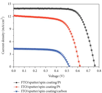
In order to compare the performance of a DSSC fabri-cated on the FTO/glass substrate and the ITO/glass substrate, using Pt counter electrodes and carbon counter electrodes [23], a conventional DSSC was prepared, as shown in
Figure 11. Figure 11 shows the photocurrent-voltage (𝐽-𝑉)
characterization of the DSSC with a sputtered compact TiO2 layer, under AM 1.5 solar irradiation with a density of 100 mW/cm2. The performance parameters are summarized
inTable 3. The short circuit photocurrent density (𝐽sc), the
open-circuit photovoltage (𝑉oc), and the fill factor for the
FTO/glass substrate using Pt counter electrodes are greater than those for the other samples. With ITO/glass, using the carbon counter electrodes, conversion efficiency decreases to 1.51%, from 4.98%, for Pt counter electrodes. This increase in the𝐽sc, the 𝑉oc, and the fill factor means that the DSSC
with the FTO/glass and a Pt counter electrode has a solar conversion efficiency of 7.65%, compared with 4.98% for the cell prepared using ITO/glass.
4. Conclusions
This study successfully deposits TiO2 and TiO2−xNx onto
ITO/glass and FTO/glass substrates. The flow rates for Ar (plasma gas), O2, and N2 (reactive gases) are varied, but the rf power, the deposition pressure, and the substrate temperature are fixed. The results show that the photo-induced hydrophilicity of TiO2−xNx film is better than that
of TiO2 film. The best absorbance of methylene blue (MB) is 0.54, for sample number 8 (the Ar/O2/N2 flow rates are 36 : 18 : 9), after UV irradiation for 4 h. This result shows
(a)
(b)
(c)
Figure 8: The SEM images of (a) sputtered TiO2compact layer on FTO/glass (sample number 8), (b) porous TiO2 on TiO2compact layers/FTO/glass, produced using the sol-gel with spin coating method and (c) porous TiO2 on compact TiO2 layers/FTO/glass, produced using the sol-gel with blade coating method.
that MB degradation for TiO2−xNx film is better than that
for TiO2 film. After annealing, the compact TiO2 layers exhibit higher optical transmittance. The TiO2porous layer on the TiO2 compact layers/FTO substrate produced using the sol-gel method exhibits a sponge-like structure, which is a prerequisite for a highly efficient DSSC. For ITO/glass with carbon counter electrodes, the conversion efficiency decreases to 1.51%, from 4.98% for Pt counter electrodes. The short circuit photocurrent density (𝐽sc), the open-circuit
TiO2compact layer Spin coating FTO Glass 1 𝜇m (a)
TiO2compact layer
Spin coating
FTO Glass
1 𝜇m
(b)
Figure 9: The SEM cross-sectional image (a) corresponding toFigure 8(b)and (b) corresponding toFigure 8(c).
20 30 40 50 60 70 80 (211) (200) (004) In te n si ty (a.u .) ITO/sputter/spin coating (101) FTO/sputter/spin coating 2𝜃 (deg)
Figure 10: The XRD patterns for the TiO2films, annealed at 450∘C.
photovoltage (𝑉oc), and the fill factor for the FTO/glass
substrate with Pt counter electrodes are greater than those of the other samples.
0.0 0.1 0.2 0.3 0.4 0.5 0.6 0.7 0.8 0 3 6 9 12 Voltage (V) FTO/sputter/spin coating/Pt ITO/sputter/spin coating/Pt ITO/sputter/spin coating/carbon 15 C u rr en t den si ty (mA/cm 2 )
Figure 11: Current-voltage plots for the DSSC with a sputtered compact TiO2 layer, using carbon and Pt counter electrodes and FTO and ITO/glass, under AM 1.5 solar irradiation with a density of 100 mW/cm2(TiO2annealed at 450∘C).
Table 3: Photovoltaic performance of DSSCs with sputtered compact TiO2layer, with carbon and Pt counter electrodes, using FTO and
ITO/glass.
𝑉oc(V) 𝐽sc(mA/cm2) Fill factor Efficiency𝜂 (%)
FTO/sputter/spin coating/Pt 0.762 13.95 0.720 7.65
ITO/sputter/spin coating/Pt 0.622 12.38 0.647 4.98
ITO/sputter/spin coating/carbon 0.522 4.33 0.668 1.51
Conflict of Interests
The authors declare that there is no conflict of interests regarding the publication of this paper.
References
[1] M. Hamadanian, A. Gravand, and V. Jabbari, “High perfor-mance dye-sensitized solar cells (DSSCs) achieved via elec-trophoretic technique by optimizing of photoelectrode proper-ties,” Materials Science in Semiconductor Processing, vol. 16, pp. 1352–1359, 2013.
[2] H. Choi, E. Stathatos, and D. D. Dionysiou, “Photocatalytic TiO2 films and membranes for the development of efficient wastewater treatment and reuse systems,” Desalination, vol. 202, no. 1–3, pp. 199–206, 2007.
[3] D. Y. Chen, C. C. Tsao, and C. Y. Hsu, “Photocatalytic TiO2thin films deposited on flexible substrates by radio frequency (RF) reactive magnetron sputtering,” Current Applied Physics, vol. 12, no. 1, pp. 179–183, 2012.
[4] H. Irie, Y. Watanabe, and K. Hashimoto, “Nitrogen-concentration dependence on photocatalytic activity of TiO2-xNx powders,” Journal of Physical Chemistry B, vol. 107, no. 23, pp. 5483–5486, 2003.
[5] Y. Nakano, T. Morikawa, T. Ohwaki, and Y. Taga, “Origin of visible-light sensitivity in N-doped TiO2 films,” Chemical
Physics, vol. 339, no. 1–3, pp. 20–26, 2007.
[6] C.-G. Kuo and B.-J. Sheen, “Seaweed chlorophyll on the light-electron efficiency of DSSC,” Journal of the Chinese Chemical
Society, vol. 58, no. 2, pp. 186–190, 2011.
[7] Y.-L. Kuo, T.-L. Su, F.-C. Kung, and T.-J. Wu, “A study of parameter setting and characterization of visible-light driven nitrogen-modified commercial TiO2photocatalysts,” Journal of
Hazardous Materials, vol. 190, no. 1–3, pp. 938–944, 2011.
[8] B. O’Regan and M. Gr¨atzel, “A low-cost, high-efficiency solar cell based on dye-sensitized colloidal TiO2films,” Nature, vol. 353, no. 6346, pp. 737–740, 1991.
[9] K. R. Bae, C. H. Ko, Y. Park et al., “Structure control of nanocrystalline TiO2for the dye-sensitized solar cell applica-tion,” Current Applied Physics, vol. 10, no. 3, pp. S406–S409, 2010.
[10] P.-C. Huang, C.-H. Huang, M.-Y. Lin, C.-Y. Chou, C.-Y. Hsu, and C.-G. Kuo, “The effect of sputtering parameters on the film properties of molybdenum back contact for CIGS solar cells,” International Journal of Photoenergy, vol. 2013, Article ID 390824, 8 pages, 2013.
[11] J. H. Qi, Y. Li, T. T. Duong, H. J. Choi, and S. G. Yoon, “Dye-sensitized solar cell based on AZO/Ag/AZO multilayer trans-parent conductive oxide film,” Journal of Alloys and Compounds, vol. 556, pp. 121–126, 2013.
[12] Y.-S. Jin, K.-H. Kim, W.-J. Kim, K.-U. Jang, and H.-W. Choi, “The effect of RF-sputtered TiO2passivating layer on the per-formance of dye sensitized solar cells,” Ceramics International, vol. 38, no. 1, pp. S505–S509, 2012.
[13] C. G. Kuo, C. Y. Hsu, S. S. Wang, and D. C. Wen, “Photocatalytic characteristics of TiO2films deposited by magnetron sputtering on polycarbonate at room temperature,” Applied Surface Science, vol. 258, pp. 6952–6957, 2012.
[14] H.-J. Kim, J.-D. Jeon, D. Y. Kim, J.-J. Lee, and S.-Y. Kwak, “Improved performance of dye-sensitized solar cells with compact TiO2blocking layer prepared using low-temperature reactive ICP-assisted DC magnetron sputtering,” Journal of
Industrial and Engineering Chemistry, 2012.
[15] H. Chang, T. L. Chen, K. D. Huang, S. H. Chien, and K. C. Hung, “Fabrication of highly efficient flexible dye-sensitized solar cells,” Journal of Alloys and Compounds, vol. 504, no. 1, pp. S435–S438, 2010.
[16] H. Seo, M.-K. Son, J.-K. Kim, I. Shin, K. Prabakar, and H.-J. Kim, “Method for fabricating the compact layer in dye-sensitized solar cells by titanium sputter deposition and acid-treatments,”
Solar Energy Materials and Solar Cells, vol. 95, no. 1, pp. 340–
343, 2011.
[17] C. G. Kuo, C. F. Yang, L. R. Hwang, and J. S. Huang, “Effects of titanium oxide nanotube arrays with different lengths on the characteristics of dye-sensitized solar cells,” International
Journal of Photoenergy, vol. 2013, Article ID 650973, 6 pages,
2013.
[18] Y. M. Sung, “Deposition of TiO2blocking layers of photovoltaic cell using RF magnetron sputtering technology,” Energy
Proce-dia, vol. 34, pp. 582–588, 2013.
[19] M. H. Abdullah and M. Rusop, “RF sputtered tri-functional antireflective TiO2 (arc-TiO2) compact layer for performance enhancement in dye-sensitised solar cell,” Ceramics
Interna-tional, vol. 38S, pp. S505–S509, 2012.
[20] L. Zhang, Y. Zhu, Y. He, W. Li, and H. Sun, “Preparation and per-formances of mesoporous TiO2film photocatalyst supported on stainless steel,” Applied Catalysis B: Environmental, vol. 40, no. 4, pp. 287–292, 2003.
[21] Y. Chen, E. Stathatos, and D. D. Dionysiou, “Sol-gel modified TiO2powder films for high performance dye-sensitized solar cells,” Journal of Photochemistry and Photobiology A: Chemistry, vol. 203, no. 2-3, pp. 192–198, 2009.
[22] H. Tomaszewski, H. Poelman, D. Depla et al., “TiO2 films prepared by DC magnetron sputtering from ceramic targets,”
Vacuum, vol. 68, no. 1, pp. 31–38, 2002.
[23] C. G. Kuo, C. F. Yang, M. J. Kao et al., “An analysis and research on the transmission ratio of dye sensitized solar cell photoelec-trodes by using different etching process,” International Journal
Submit your manuscripts at
http://www.hindawi.com
Hindawi Publishing Corporation
http://www.hindawi.com Volume 2014 Inorganic Chemistry International Journal of
Hindawi Publishing Corporation
http://www.hindawi.com Volume 2014
Photoenergy
Hindawi Publishing Corporation
http://www.hindawi.com Volume 2014
Carbohydrate
Chemistry
International Journal ofHindawi Publishing Corporation
http://www.hindawi.com Volume 2014 Journal of
Chemistry
Hindawi Publishing Corporation
http://www.hindawi.com Volume 2014
Physical Chemistry
Hindawi Publishing Corporation http://www.hindawi.com Analytical Methods in Chemistry Journal of Volume 2014 Bioinorganic Chemistry and Applications Hindawi Publishing Corporation
http://www.hindawi.com Volume 2014
Spectroscopy
International Journal ofHindawi Publishing Corporation
http://www.hindawi.com Volume 2014
The Scientific
World Journal
Hindawi Publishing Corporationhttp://www.hindawi.com Volume 2014 Medicinal Chemistry
Hindawi Publishing Corporation
http://www.hindawi.com Volume 2014
Chromatography Research International Hindawi Publishing Corporation
http://www.hindawi.com Volume 2014
Applied ChemistryJournal of
Hindawi Publishing Corporation
http://www.hindawi.com Volume 2014
Hindawi Publishing Corporation
http://www.hindawi.com Volume 2014
Theoretical Chemistry Journal of
Hindawi Publishing Corporation
http://www.hindawi.com Volume 2014
Journal of
Spectroscopy
Analytical Chemistry
Hindawi Publishing Corporation
http://www.hindawi.com Volume 2014
Journal of Hindawi Publishing Corporation
http://www.hindawi.com Volume 2014 Quantum Chemistry Hindawi Publishing Corporation
http://www.hindawi.com Volume 2014 International
Electrochemistry
International Journal ofHindawi Publishing Corporation
http://www.hindawi.com Volume 2014
Hindawi Publishing Corporation
http://www.hindawi.com Volume 2014