Extended depth of field system for long distance iris acquisition
Yung-Lin Chen
a, Sheng-Hsun Hsieh
a, Kuo-En Hung
a, Shi-Wen Yang
a, Yung-Hui Li
b,
Chung-Hao Tien
aa
Dep. of Photonics and Institute of Electro-optical Engineering, National Chiao Tung Univ./1001
University Rd., Hsinchu Taiwan 300, R.O.C.
b
Dept. of Information Engineering and Computer Science, Feng Chia Univ./100 Wenhwa Rd.,
Seatwen, Taichung Taiwan 407, R.O.C.
ABSTRACT
Using biometric signatures for identity recognition has been practiced for centuries. Recently, iris recognition system attracts much attention due to its high accuracy and high stability. The texture feature of iris provides a signature that is unique for each subject. Currently most commercial iris recognition systems acquire images in less than 50 cm, which is a serious constraint that needs to be broken if we want to use it for airport access or entrance that requires high turn-over rate . In order to capture the iris patterns from a distance, in this study, we developed a telephoto imaging system with image processing techniques. By using the cubic phase mask positioned front of the camera, the point spread function was kept constant over a wide range of defocus. With adequate decoding filter, the blurred image was restored, where the working distance between the subject and the camera can be achieved over 3m associated with 500mm focal length and aperture F/6.3. The simulation and experimental results validated the proposed scheme, where the depth of focus of iris camera was triply extended over the traditional optics, while keeping sufficient recognition accuracy.
Keywords: iris recognition, extended depth of field, cubic phase mask
1. INTRODUCTION
Using biometric signatures for identity recognition has been practiced for centuries. Recently, biometric technology has becoming an important research topic. The personal attributes used for a biometric identification system can be physiological, such as facial features, fingerprints, iris texture, retinal scans; or behavioral traits of an individual, such as voice, signature and keystroke style. Among these methods, iris recognition is the most attractive one to the researchers because of the nature of randomness of iris texture. Moreover, recognition based on iris texture has many advantages such as high entropy density, stability of the iris texture over a lifetime, and the high independency across individuals (even for the twins). According to the research from Prof. J. Daugman, we can see that the probability of false identification can be the order of ten to the negative ten1-3.
There are several steps in iris recognition, including image acquisition, iris localization, feature extraction, signature encoding, and matching the iris codes to the stored database for recognition. Iris recognition has been applied to many fields, such as airport security, computer security and bank transactions, but existing iris recognition systems have disadvantages. One of them is the shallow depth of field which leads to difficulty in capturing qualified images, or the user will not be identified successfully. This issue becomes particularly important when we want to build a more unconstrained iris recognition system. Thus the focus of this paper is how to build a system with large depth of field (DoF) for capturing iris images.
Several research have used wavefront coding technology4 to extend the depth of field (EDoF) of the iris recognition
system5-6. Wavefront coding is the approach which employs a phase mask to modify the incoherent optical system, and
Subject
*
Recognition result
Phase mask
Wavefront coding imaging Coded blurry images
at different focal planes Image restoration filter
Decoded images at different focal planes
C> Mne
4 *
Matching Feature Extraction Iris Normalization Iris SegmentationIl
Iris recognition processing2. METHOD TO EXTEND THE DEPTH OF FIELD
2.1 The concept of wavefront coding technology
Wavefront coding imaging is a novel technology which can substantially increase the DoF of the optical system by merging the optical design and image processing. The concept is to place an asymmetric plate at the pupil to form point spread function which don’t vary significantly over large range of defocus, alternatively stated, the modulation transfer function (MTF) of the system can keep invariant and boost the modulation at higher spatial frequency with increasing defocus errors. The phase mask is designed for a specific aberration, such that the image looks blurry which is different from the design concept of conventional imaging, in this way the optical system is coded by the wavefront and decoded by digital filter. The phase profile is given by4
( )
x
,
y
exp
(
j
[
x
3y
3]
)
p
=
α
+
(1)where p(x, y) is the pupil function and the indices x, y are normalized coordinates in the pupil plane, furthermore, the choice of α governs the overall strength of the mask, in other words, the values of α determines the phase deviations, larger α correspond to larger phase deviations which yield high focus invariance but decreases MTF values.
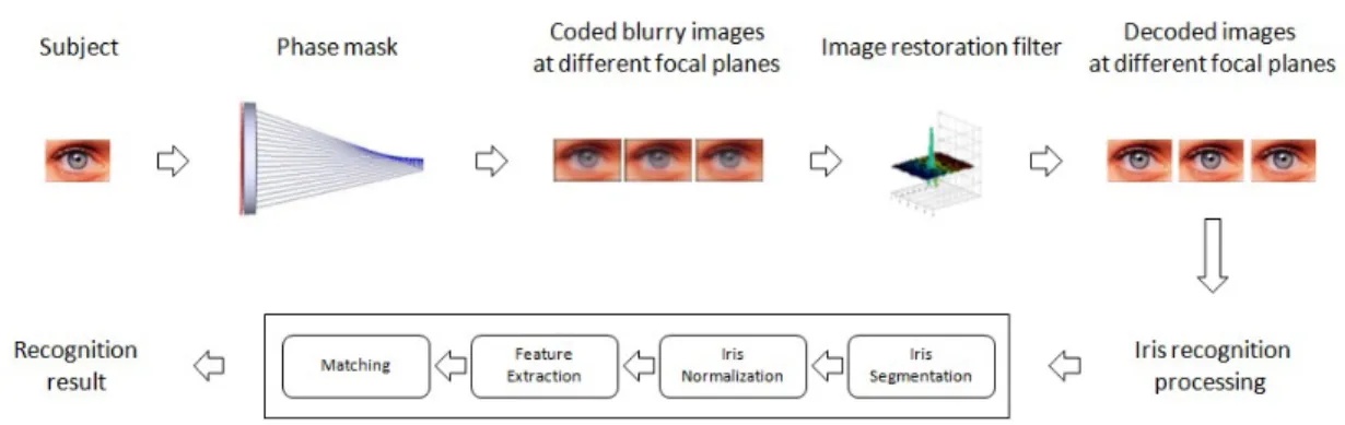
The schematic diagram of the wavefront coding system for long range iris recognition system is shown in Figure 1. First, the image is acquired by the system, because the PSF is invariant to defocus, the coded images over large range of defocus can keep invariant to each other. Second, the images can be accurately decoded by a simple digital signal processing. Finally, the iris recognition processing can be applied to the proposed images, including image segmentation module which localizes the iris and segments out the iris feature for signature analysis, iris encoding module which converts the segmented feature into a series of binary codes, iris score module which compares the iris codes with the stored database by calculating the iris score such as Hamming distance, then the threshold of Hamming distance decides the acceptance or rejection, the schematic diagram for EDoF iris recognition system is shown in Figure 1.
Figure 1: The schematic diagram for EDoF iris recognition system.
3. OPTICAL SYSTEM DESIGN
3.1 MagnificationIn the iris recognition process, the suitable size of iris images is suggested to be at least larger than 150 pixels7 across its
diameter. In this paper, we use imaging sensors with higher resolution to acquire the iris image which extends 300 pixels. In addition, the average diameter of the iris is about 12mm8, so the magnification of the acquired iris image can
be decided according to the size of the imaging sensor. After the magnification factor is calculated, we are able to find the relationship between focal length and stand-off distance of the subject.
MV1-D2080 IR CCD datasheet Sigma APO 150-500mm F5-6.3 DG OS HSM Optical format 23.5mm Angle of View 16.4-5 degrees Resolution 2080
×
2080 Minimum Focusing Distance 220cmPixel Size 8µm
×
8µm Maximum Magnification 1:5.2Dark current 0.65fA/pixel Diameter 86mm
Table 1. Specifications of MV1-D2080 IR CCD and Sigma APO 150-500mm F5-6.3 DG OS HSM.
The imaging sensor used in our system is a MV1-D2080 IR CCD, specified in Table 1, containing 2080 by 2080 square pixels, and each has a size of 8µm, and the optical format is 23.5mm. Therefore, if we want to acquire the iris image with 300 pixels, the image size on the sensor must be 2.4mm, which means that the magnification of the system is 0.2. When the magnification of the system is decided, we can determine the focal length of the system directly according to the lens’ maker formula (2), where f represents focal length, s' the image distance, and s the object distance, as we know s'/s is the magnification of the optical system. In our case, the object distance is 3m, so the suitable focal length for acquiring iris image with 300 pixels is 500mm.
s
s
f
1
'
1
1
−
=
(2)3.2 Phase profile design
In section 3.1, we determined the appropriate focal length and subject distance of the iris capturing system. In this section, we will discuss about how to design the phase mask. First, we chose an off-shelf F-mount telephoto camera as the capturing system, which is a Sigma zoom lens with focal range from 150-500mm and aperture from F/5-F/6.3. In order to design the profile with appropriate α value, we should carefully balance the trade-off between MTF of the coded image and the desired EDoF range. Furthermore, it is important to place the cubic phase mask at the correct position near the pupil of the optical system, so the PSFs can keep invariant within different defocus and pupil aberration between on axis and off axis PSFs can be avoided.
Before designing the cubic phase mask profile, we have to simulate an image capture system which has same focal range (150mm-500mm) and aperture range (F/5-F/6.3) as the off-shelf telephoto camera first. Such system has 21 elements and lens shape is similar to the off-shelf telephoto camera when the cubic phase mask is placed close to the pupil position. The appropriate α value of the pattern can be optimized by using lens design program Zemax and Matlab simultaneously. We utilize the user defined operand (UDOP) capability of Zemax which can communicate with Matlab, therefore, the numerical calculations can be processed in Matlab such as PSF similarity, mean square error (MSE), etc, and predicted results are directly returned to the Zemax optimization routines. Then the appropriate α value of the phase profile can be obtained.
Now, before the optimization process begins, we have to decide which criterions (MTF or MSE) to use as the objective function. It should be noticed that the MTF of coded system can’t cross zero, otherwise the ringing effects will occur due to information loss, so it is important to determine the threshold of MTF. Although the wavefront coding system has already tolerate defects of lens manufacturing, the MTF degradation by lens manufacturing error must be taken into consideration. And referring to the appropriate MTF value at Nyquist frequency9-10 of the wavefront coded system, we
set the threshold of MTF at Nyquist frequency to be larger than 0.1. Besides, in order to obtain high focus invariance, an objective function which minimizes the MSE difference between on focus and defocus coded images is used.
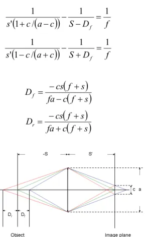
As mentioned before, there is trade-off between MTF and EDoF range, which means that large value of α yields high focus invariance but degrades MTF value. In this study, we would like to achieve 10 times DoF extend as the initial value. The DoF of traditional optical system can be predicted in the following calculations. Figure 4 illustrates the concept of the traditional DoF, where s represents the object distance, s' the image distance, f the focal length of the lens. Their relation can be described by equation (2). When the subject is located in front or behind the focal point, it causes blur spot on the image plane. We use circle of confusion (CoC) c to define the acceptable blur spot which the human eye can not distinguish. CoC is also an important factor that determines the DoF of the system. Let Dr and Df represent the
-S S'
fi
Ob ect Image plane
and (4), where a denotes the entrance pupil diameter. Dr and Df can be defined by equation (5) and (6). In general, the
CoC of the human eye is 0.2mm under the distance of distinct vision 25cm. Suppose the photo of the 35mm format camera is printed to size 8
×
10, which is approximately 8 times enlarged. Then the normal CoC for 35mm format (24mm×
36mm) is 0.025mm. Furthermore, because CoC is proportional to the diameter of the sensor, so the equivalent CoC of our system is 0.014mm, and the resulting Dr and Df are 2.64 and 2.65mm, respectively. In order to extended theDoF 10 times compared to the conventional system, we request the MSE of the coded images to be invariant within the ±25mm defocus range where "
+
" means the subject behind the focal point, and "−
" means the subject in front of the focal point. The optimal α value can be obtained by using the criterions mentioned above is approximately 42.(
)
(
c
a
c
)
S
D
f
s
f1
1
/
1
'
1
=
−
−
−
+
(3)(
)
(
c
a
c
)
S
D
f
s
f1
1
/
1
'
1
=
+
−
+
−
(4) and(
)
(
f
s
)
c
fa
s
f
cs
D
f+
−
+
−
=
(5)(
)
(
f
s
)
c
fa
s
f
cs
D
r+
+
+
−
=
(6)Figure 2: The schematic diagram for EDoF iris recognition system.
4. SIMULATION RESULT
4.1 Point spread functionTo measure the PSF of the system, the value of α we used in the work was 42 and the wavefront of the mask is illustrated in Figure 3(a). Using this figure as the input video signal and Mitutoyo 10X objective with monochromatic CCD to capture the PSF, the results are shown in Figure 4. The first row is the system without cubic phase mask and the second row is the system with cubic phase mask. The PSFs from left to right represent onfocus and defocus +25mm, respectively. The geometrical size and energy distribution of the PSFs in the first row are varying with different levels of defocus while the PSFs in the second row can be kept almost constant. In other words, the cubic phase mask makes the PSF insensitive to defocus.
(a,1) (a,2)
9
(a,3) (a,4) (a,5)
On focus Defocus +2.5mm Defocus +5mm Defocus +7.5mm Defocus +25mm
(b,1) (b,2) (b,3) (b,4) (b,5)
On focus Defocus +2.5mm Defocus +5mm Defocus +7.5mm Defocus +25mm
(origin) On focus (b,1) On focus On focus (a,2) (a,3) Defocus +2.5mm Defocus +5mm (b,3) Defocus +2.5mm Defocus +5mm (b,2) (c,2) Defocus +2.5mm (c,3) Defocus +5mm (a,4) Defocus +7.5mm (b,4) Defocus +7.5mm Defocus +7.5mm (a,5) Defocus +25mm (b,5) Defocus +25mm (c,5) Defocus +25mm
Figure 3: (a) Phase modulation of cubic phase mask in Fresnel lens form (b) Phase profile of the pupil function.
Figure 4(a) The PSF of the system without cubic phase mask (b) The PSF of the system with cubic phase mask.
4.2 Result for image acquisition
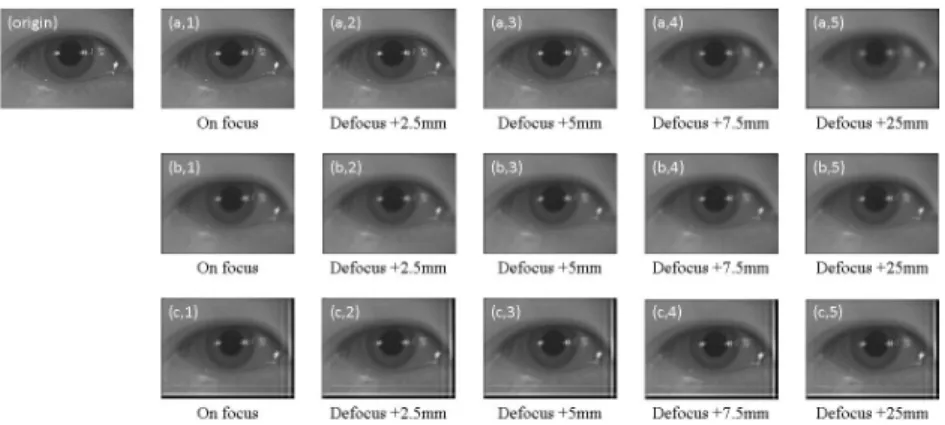
Figure 5 shows the simulated images which are calculated by the convolution of the captured PSFs in Figure 4 and a iris picture. Figure 5(a) and Figure 5(b) represent the iris images without and with cubic phase mask respectively. We can see the iris images are sensitive to the defocus in Figure 5(a) while the those in Figure 5(b) show consistent similarity. Using the Wiener filter to deconvolve the blur iris images, the restored images are showed in Figure 5(c).
Figure 5: (a) The simulated iris image without cubic phase mask (b) The simulated iris image with cubic phase mask (c) The simulated iris image with cubic phase mask after restored by Wiener filter.
(b.3)
0a
0.3
II
with cubic phase mask +without cubic phase mask0.0 0 10 15 defocus (mm) 20 threshold 25
4.3 Simulated Iris recognition
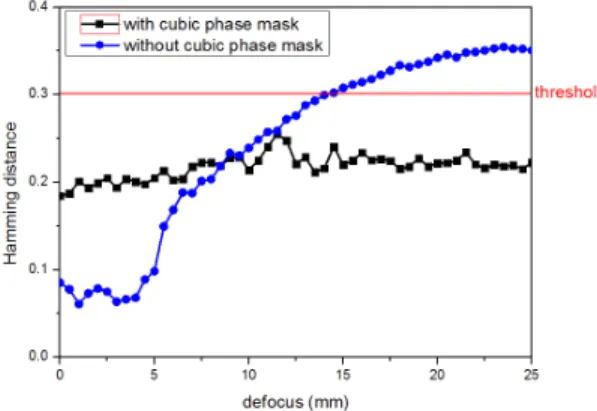
We performed iris recognition using the simulated onfocus and defocus iris images described in previous section. There are several steps in iris recognition, including image acquisition, iris localization, iris normalization, feature extraction, and matching the iris codes to the stored database for recognition. Degree of matching between two irises is described by Hamming Distance (HD), then the appropriate threshold of HD is chosen to decide the acceptance or rejection. Figure 6 shows the HD distribution of authentic comparison (images from the same eye matched between each other) with (black curve) and without (blue curve) cubic phase mask under different defocus. Since the minus defocus and plus defocus is similar, here we only show the plus defocus in our simulation result. In conventional acquisition system (without cubic phase mask, denoted by the blue curve), the operational range is constrained within ±14.5mm when using HD=0.3 as the threshold. As we place the cubic phase mask in pupil plane, the operational range can be extended over ±25mm. Depth of field is proportional to depth of focus, so the extended depth of field is equal to 25/14.25=1.72 times over the conventional iris acquisition system.
Figure 6: The Hamming distance without/with cubic phase mask under different defocus by stimulation.
5. EXPERIMENTAL RESULT
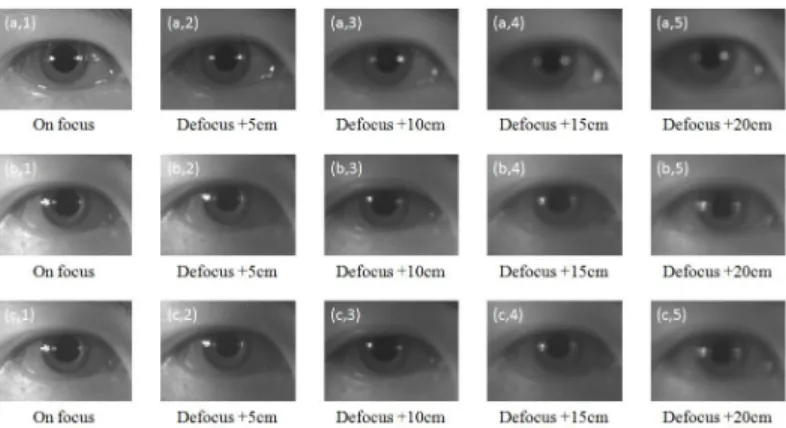
Our experimental system setup is in Figure 7. When the subject is passing the gate, the camera system captures the iris image automatically. The working distance is set for three meters. The subject’s position is varying from 0 to 30 cm away from the onfocus point. Iris image is captured at every 1 cm interval. Figure 8 shows the captured images in our system. Figure 8(a) and Figure 8(b) show the iris images without and with cubic phase mask, respectively. We can see again the iris images are sensitive to the defocus in Figure 8(a) while those in Figure 8(b) show consistent similarity. Using the Wiener filter to deconvolve the blur iris images, the restored images are showed in Figure 8(c).
On focus Defocus +5cm On focus Defocus +5cm On focus Defocus +5cm (a,3) Defocus +10cm (b,3) Defocus +10cm (c,3) Defocus +10cm (a,4) Defocus +15cm Defocus +15cm Defocus +15cm Defocus +20cm Defocus +20cm Defocus +20cm o 0.4 N 0 03 E 0.2 0.1 OD
t with cubic phase mask without cubic phase mask
o 10 15 20
defocus (cm)
25 30
Figure 8: (a) The iris image without cubic phase mask (b) The iris image with cubic phase mask (c) The iris image with cubic phase mask after restored by Wiener filter.
Figure 9 shows the HD distribution of authentic comparison with (black curve) and without (blue curve) cubic phase mask under different defocus. In conventional acquisition system, the operational range is constrained within ±3cm when using HD=0.3 as the threshold. As we place the cubic phase mask in the pupil plane, the operational range can be extended ±10cm. The extended depth of field is equal to 10/3=3.3 times over the conventional iris acquisition system. The extended of DoF in experimental result is much greater than simulation result (which is 1.72).
Figure 9: The Hamming distance without/with cubic phase mask under different defocus.
6. CONCLUSIONS
In the paper, we used the cubic phase mask for extending the depth of field of the long acquisition system for iris recognition and the result shows that the image is insensitive to defocus but also becomes blurry due to the large size of PSFs. The simulation and experimental result shows that the DoF was 1.72/3.33 times extended compared to traditional optics, while keeping sufficient recognition accuracy. Our future work includes trying different phase coding scheme to explore optimal EDoF setup for iris images.
7. ACKNOWLEDGMENT
REFERENCE
[1] J. Daugman, "The importance of being random: statistical principles of iris recognition," Pattern Recognition 36, 279-291 (2003)
[2] J. Daugman, “High confidence visual recognition of persons by a test of statistical independence," IEEE Transaction on Pattern Analysis and Machine Intelligence 15(11), 1148-1161, (1993)
[3] J. Daugman, "How iris recognition works," IEEE Transaction on Circuits and Systems for Video Technology 14(1), 21-30, (2004)
[4] E. R. Dowski, W. T. Cathey, "Extended depth of field through wavefront coding," Applied Optics 34(11), 1859-1866 (1995)
[5] Robert Plemmons, "Computational Imaging Systems for Iris Recognition, " Proc .SPIE 5559, 346-357 (2004) [6] D. Shane Barwick, "Increasing the information acquisition volume in iris recognition systems," Applied Optics 47,
4684-4691 (2008)
[7] ANSI INCITS 379-2004: Iris Image Interchange Format
[8] J. Forrester, A. Dick, P. Mcmenamin, and W. Lee, "The Eye: Basic Sciences in Practice," W. B. Saunder, London, UK (2001)
[9] Kenneth Kubala, Edward Dowski, James Kobus, Bob Brown, "Design and optimization of aberration and error invariant space telescope systems," Proc. SPIE 5524, 54-65 (2004)
[10] Sherif S. Sherif, E. R. Dowski, and W. Thomas Cathey, "A logarithmic phase filter to extend the depth of field of incoherent hybrid imaging systems," Algorithms and Systems for Optical Information Processing V, 272-279 (2001)
[11] Spatial Light Modulator LC2002. HOLOEYE Photonics AG Home Page. http://www.holoeye.com (2010) [12] http://www.holoeye.com/download_area.html