Structure and property of epitaxial titanium oxynitride grown on MgO(001)
substrate by pulsed laser deposition
Hien Do
a,⁎
, Yue-Han Wu
a, Van-Truong Dai
b, Chun-Yen Peng
a, Tzu-Chun Yen
a, Li Chang
aa
Department of Materials Science and Engineering, National Chiao Tung University, Hsinchu, Taiwan 300, ROC
bDepartment of Electronics Engineering, National Chiao Tung University, Hsinchu, Taiwan 300, ROC
a b s t r a c t
a r t i c l e i n f o
Article history: Received 18 July 2012
Accepted in revised form 3 November 2012 Available online 16 November 2012 Keywords:
Titanium oxynitride Epitaxial growth Pulsed laser deposition Nanoindentation
High-quality epitaxial TiNxOyfilms with different oxygen content were deposited on MgO(001) substrates by
pulsed laser deposition method. The chemical composition of the depositedfilms was determined by X-ray photoelectron spectroscopy. X-ray diffraction results showed that the TiNxOyfilms are heteroepitaxially
grown on MgO with good crystallinity and their lattice parameters decrease with increased oxygen concentration. Transmission electron microscopy analyses showed that TiNOfilms contain a low density of dislocations. Atomic force microscopy revealed very smooth surfaces of TiNxOyfilms with roughness of
0.26–0.29 nm. The resistivity of TiNxOyfilms determined by Hall measurement was about 28–33 μΩ cm.
Nanoindentation measurements showed thefilm hardness and Young's modulus of about 23–26 GPa and 400–430 GPa, respectively.
© 2012 Elsevier B.V. All rights reserved.
1. Introduction
Titanium nitride (TiN) belongs to the family of refractory transition metal nitrides and possesses excellent optical, chemical, and physical properties that lead to many applications such as hard coating material, hard mask, and diffusion barriers[1–6]. The addition of oxygen to TiN matrix to form a new composition, i.e., titanium oxynitride (TiNxOy),
has recently attracted attention. This is due to the fact that titanium oxynitride benefits from many remarkable properties of both metallic oxides (chemical stability, optical properties) and nitrides (hardness, wear resistance). Moreover, the optical and electrical properties of TiNxOycan be tailored between those of metallic nitrides and those of
corresponding ionic oxides by varying the oxygen/nitrogen ratio[7,8]. Therefore, titanium oxynitride has been widely used in a wide range of applications such as decorative and wear-resistant coating[7,8], transparent IR window electrodes[7], solar collector devices[7,9], elec-trical switchable windows[10], and photocatalysis[11]. In comparison with TiN, titanium oxynitride has shown new interesting properties that can be used as biomaterials[12,13], memory devices[14]. In addi-tion, titanium oxynitride nanocrystals with NaCl (rock-salt) structure especially show ultraviolet light emission in photoluminescence spectra at room temperature contrasted with the TiN case[15]. Another attrac-tive motivation to study TiNxOyis that the presence of oxygen in the
TiNfilms has beneficial effects on diffusion barrier performance for Al, e.g., the possibility of reducing the grain boundary diffusion and de-creasing the contact failure rate during high temperature cycling
[16–20].
TiNxOyfilms have been deposited by various processes, including
the oxidation of TiN[21], nitridation of TiO2[22], and simultaneous
mixing of elements or precursors methods such as magnetron sputtering[8], evaporation[9], metal organic chemical vapor deposition (MOCVD)[23], and pulsed laser deposition (PLD)[24]. In most cases, however, titanium oxynitridefilms have been reported to be amor-phous or polycrystalline. Epitaxial growth of TiNxOyhas been rarely
studied in contrast with the case of TiN. The deposition of epitaxial
TiN-xOycan improve electrical conductivity and overcome the problem of
fast grain boundary diffusion of dopants and impurities along the co-lumnar grains of the polycrystallinefilms [18–20,25]. Furthermore, the study of epitaxial films can improve our understanding of the basic properties of TiNxOy.
In this article, we report the successful growth of high-quality epitaxial titanium oxynitrides with NaCl structure on MgO(001) sub-strates by pulsed laser deposition (PLD). The crystallinity, lattice parameter, microstructure, morphology, electrical, and mechanical properties of TiNxOywith different oxygen content were investigated.
Defect analyses were also performed under various two-beam trans-mission electron microscopy (TEM) conditions.
2. Experimental
Titanium oxynitridefilms were grown in the PLD chamber with base pressure of 1 × 10⁻⁶Torr. A 2-inch MgO(001) substrate was ultrasonically cleaned in acetone, then dried with nitrogen gas, and im-mediately loaded into the vacuum chamber. The substrate was placed opposite to a 2-inch oxygen-containing TiN target (TiNO0.064) at a
dis-tance of 14 cm. The target was irradiated with a KrF (λ=248 nm) laser beam at an angle of 45°, and rotated during deposition. Before
⁎ Corresponding author. Tel.: +886 3 5731615; fax: +886 3 5724727. E-mail address:[email protected](H. Do).
0257-8972/$– see front matter © 2012 Elsevier B.V. All rights reserved. http://dx.doi.org/10.1016/j.surfcoat.2012.11.008
Contents lists available atSciVerse ScienceDirect
Surface & Coatings Technology
j o u r n a l h o m e p a g e : w w w . e l s e v i e r . c o m / l o c a t e / s u r f c o a tTiNxOydeposition, the MgO substrates were heat-treated at 700 °C for
30 min to obtain a smooth and clean surface. The deposition process was then carried out under several different conditions to obtain TiNxOy
films with different oxygen content while the substrate temperature wasfixed at 700 °C for all cases. After the deposition process had been completed, the substrate was cooled down to room temperature in 90 min. Chemical composition of the depositedfilms was determined by X-ray photoelectron spectroscopy (XPS) (ULVAC-PHI, PHI Quantera SXM) by using a monochromatic Al Kα radiation source. For the XPS quantitative analysis, the peak area was corrected with relative sensitiv-ity factors from a manufacturer's program and database. A Bede D1 high-resolution X-ray diffractometer, equipped with a two-bounce Si 220 channel-cut collimator crystal, a dual channel Si 220 analyzer crys-tal, and CuKα1radiation (λ=1.5406 Å), was used to investigate the
crystallinity and strain state of thefilms. Cross-sectional TEM specimens were prepared by tripod polishing method and focused ion beam (FIB) technique (FEI Nova 200). The tripod polished specimens were Ar-ion milled at angles of 4–6° and acceleration voltage of 4–5 kV. TEM speci-mens were then examined in a JEOL 2010F microscope. Atomic force microscopy (AFM) (D3100) was used to investigate the surface mor-phology of thefilms. Hall measurements were carried out to determine the resistivity and carrier concentration of the TiNxOyfilms.
The mechanical properties of the deposited TiNxOy films were
characterized by using a MTS Nanoindenter XP system with a dia-mond Berkovich tip. The continuous-stiffness-measurement (CSM) mode was used with a harmonic force at 45 Hz imposed on the in-creasing load. To extract the accurate hardness and elastic modulus of the thin TiNxOy films on the MgO substrates, we applied the
model developed by Han Li et al.[26], in which the substrate effect caused by elastic mismatch between the film and substrate was taken into account.
3. Results and discussion
The chemical composition of the depositedfilms was determined by XPS.Fig. 1shows the XPS depth profiles of samples A and B with different oxygen content. As seen inFig. 1, the chemical composition of both samples A and B is uniform and can be determined as TiN0.97O0.23(sample A) and TiN1.11O0.10(sample B), suggesting that
the addition of oxygen atoms occurred in the overstoichiometric TiNx(x > 1). The chemical states of both TiNOfilms were identified
by examining Ti-2p, O-1s, and N-1s XPS spectra in high-resolution
Fig. 1. XPS depth profiles for samples A and B with different oxygen content.
Fig. 2. XPS spectra for A) Ti-2p, B) N-1s, C) O-1s after Ar sputtering for one minute of samples A and B. The spectra are deconvoluted into components of titanium nitride, titanium oxynitride, and titanium dioxide[21,27,28].
mode after Ar sputtering for 1 min (~ 2 nm). As shown inFig. 2A, the Ti-2p3/2peak of samples A and B can be deconvoluted into two main
components of Ti–N bonding (454.9 eV corresponding to titanium nitride) and N–Ti–O bonding (~456.7 eV corresponding to titanium oxynitride) with a very small amount of Ti–O bonding (458.4 eV corresponding to titanium dioxide)[21,27,28]. The N-1s spectra for samples A and B (Fig. 2B) reveal a small amount of chemisorbed mo-lecular nitrogen (398.7 eV) and two main components of titanium ni-tride (397 eV) and titanium oxynini-tride (396.2 eV)[27]in agreement with the results determined from the Ti peaks. InFig. 2C, sample A shows a stronger O-1s signal compared with that of sample B due to the higher oxygen concentration incorporated into sample A.
The X-ray diffraction (XRD) patterns of both samples A and B in
Fig. 3show only TiNxOy(002) and TiNxOy(004) reflections in addition
to the MgO ones, suggesting that (001) oriented single-phase titanium oxynitride have been deposited on MgO(001) substrates in our experi-mental conditions. Also, TiNxOy(002) and TiNxOy(004) reflections
appear at 42.46° and 92.82° for sample A, and 42.41° and 92.63° for sample B, indicating that they have larger out-of-plane interplanar spacing than MgO. The X-ray rocking curves in the inset ofFig. 3show that the full width at half maximum (FWHM) of (002)TiNxOyis about
58 arcsec for sample A, and 64 arcsec for sample B, implying that both TiNxOyfilms deposited on MgO have a very good quality (the FWHM
of the MgO substrate is 42 arcsec). The X-rayϕ-scan was done on bothfilms to verify the orientation relationship between the TiNxOy
and MgO substrates. As seen inFig. 4, four {022} peaks of MgO and TiNO appear at the sameϕ angles with a separation of 90°. This result suggests that the TiNOfilms have epitaxially grown on the MgO sub-strates with the cube-on-cube relationship of TiNO(001) // MgO(001) and TiNO[100] // MgO[100].
To investigate the effect of oxygen content on the strain state as well as the lattice parameters of TiNxOyfilms, XRD reciprocal space
maps (RSM) of the asymmetric (113)MgO and (113)TiNxOyre
flec-tions were acquired. As shown inFig. 5, the asymmetric (113)MgO and TiNxOyreflections for both samples are almost vertically aligned,
implying that TiNxOylattices are in coherency with the MgO one.
Hence, both TiNxOyfilms may be under fully compressive strain as a
result from lattice mismatch and thermal mismatch with MgO. The thermal strain was induced due to a large difference in the coefficient of thermal expansion (CTE) of MgO and TiNxOy(αMgO=13× 10−6K−1
and assume αTiNO~αTiN= 9.35 × 10⁻⁶K−1 [29]). When substrate
temperature dropped from 700 ° C down to room temperature, the
MgO substrate contracted more than the TiNxOy layer, resulting in
the generation of a compressive strain of−0.27% in the TiNxOylayer.
The out-of-plane, c, and in-plane, a, lattice parameters of TiNO can be determined as follows: c = 3/Qz, and a¼
ffiffiffi 2 p
=Qx, where Qzand Qxare
vertical and horizontal vectors that lie along MgO[001] and MgO[110] directions, respectively[29]. The relaxed lattice parameter aocan be
cal-culated from c and a by using equation: ao= c[1−2ν(c−a)/c(1+ν)]
[29], whereν is the Poisson ratio of the deposited films. Due to the slight difference in the Poisson ratio between TiN and TiO (νTiN= 0.22[29]
andνTiO= 0.232[30]) and the large ratio of N/O of the deposited
TiNO films, we can assume that νTiNO~νTiN. By using MgO(113)
peak as reference (aMgO= 4.2112 Å[29]), the lattice parameters (c,
a, and ao) and in-plane residual strainε||of samples A and B can be
calculated and are listed inTable 1. The results show that the lattice parameters of TiNxOyfilms decrease with the increase of oxygen
con-centration but still lie in the lattice parameter range between bulk TiN (aTiN= 4.2417 Å from the powder diffractionfile PDF 38-1420)
and bulk TiO (aTiO= 4.1770 Å, PDF 8-117). Those results are also in
good agreement with the values reported in ref.[31]. Due to the fact that the radius of oxygen anion is smaller than that of the nitro-gen anion, the substitution of oxynitro-gen for nitronitro-gen enables the lattice parameter to decrease with increased oxygen concentration[32]. Additional to the effect of anion radii on the lattice parameter, the ef-fect of electrostatic repulsion between N and O anions around Ti va-cancies has also been taken into consideration[33]. Indeed, the XPS results above suggest that the substitution of oxygen for nitrogen occurs in the over-stoichiometric TiNx, and such a non-stoichiometric structure
has been reported to contain many Ti vacancies[34]. Therefore, there may have been an electrostatic repulsion between anions around Ti va-cancies. Besides, the N atoms need three electrons to close its shell in order to achieve the most stable configuration (N−3) while the O
atoms only need two (O−2)[33]. Hence, the replacement of N3−by O−2induces a decrease in the electrostatic repulsion between the an-ions around the Ti vacancies and consequently the lattice parameter decreases.
The second source of compressive strain can be generated from the film/substrate lattice mismatch that is determined as δ=[aMgO−afilm] /
aMgO.δ is −0.73% for pure TiN, −0.716% for sample B, and −0.655% for
sample A. The result also shows that more oxygen content incorporated into the depositedfilms can reduce the lattice mismatch between MgO and TiNxOy. The corresponding critical thickness of samples A and B can
be estimated theoretically as ~10 nm at room temperature. In other words, the addition of oxygen can result in the high-quality titanium
Fig. 3. XRD 2θ-θ scans for TiNxOyfilms. XRD ω-scan is shown in the inset.
Fig. 4. XRDϕ-scan of {022} reflections for TiNxOyfilm grown on the MgO substrate,
showing epitaxial relationship between thefilm and the substrate is TiNxOy(001) //
oxynitride with a composition which can make the depositedfilms to be excellently coherent with MgO, contrasting with the case of pure TiN on MgO. Indeed, the authors in ref.[29]have shown that the stoi-chiometric TiNfilm is semi-coherent with MgO that resulted from the generation of misfit dislocations at the TiN/MgO interface.
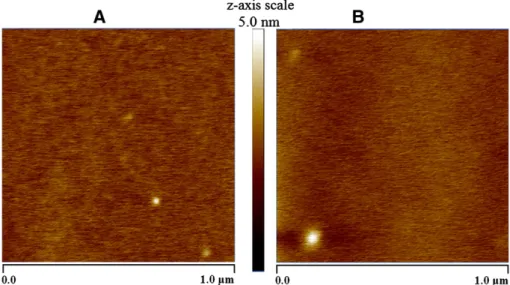
The surface morphology of the MgO substrates and the deposited films was examined by AFM. The film surface of samples A and B (Fig. 6) and the MgO substrate (not shown) is very uniform and smooth with root-mean-square roughness of 0.29 nm (sample A), 0.26 nm (sample B), and 0.18 nm (MgO).
The resistivity of TiNxOyfilms measured by the Hall measurement
method was found to be 33μΩ cm and 28 μΩ cm for samples A and B, respectively. In addition, the carrier concentration of samples A and B can be determined as high as 3.2 × 1022cm−3and 2.8 × 1022cm−3,
indicating the metallic conduction behavior of the depositedfilms. The resistivity of the TiNxOyfilms are much smaller than that of the
bulk TiO (190μΩ cm) and about two times larger than that of the pure epitaxial TiN (~ 15μΩ cm) [25]. It has been shown that the increasing resistivity in the series of TiN, TiNxOy, and TiO can be
explained by considering the free electron concentration[35]. The lower free electron concentration results in poor conductivity of TiO and to a lesser extent TiNxOy[35]. The results can be compared
with those reported in ref.[25], in which the resistivity of the epitax-ial TiNxOyfilms, with oxygen concentration of 7.02–11.11 at.%, is
about 21.0–32.3 μΩ cm[25]. Hence, compared with the polycrystal-line TiNOfilms that have been shown to have the resistivity in the order of magnitude from mΩ cm to Ω cm[27,28]the epitaxial growth of the TiNOfilms certainly can greatly improve electrical conductivity. The hardness (H) and Young's modulus (E) values are determined to be 23 ± 1.1 GPa and 400 ± 4.3 GPa for sample A, whereas sample B showed higher values of 26 ± 1.2 GPa and 430 ± 5.5 GPa, res-pectively. The results are closed with the reported values of stoichio-metric TiN(001) with H ~ 20 ± 0.8 GPa and E ~ 445 ± 38 GPa[36]. It also clearly shows that both the hardness and elastic modulus of the TiNxOyfilms decrease as the amount of oxygen increases. The
hard-ness and elastic modulus may also depend on the nitrogen content as they increase for the x in TiNxOythat increases from 0.97 to 1.11.
Fig. 5. Reciprocal space maps of the asymmetric (113)MgO and (113)TiNxOyreflections for A) sample A and B) sample B.
Table 1
In-plane a, out-of plane c, and relaxed aolattice parameters, and in-plane residual
strainε||of TiNxOyfilms.
Sample a (Å) c (Å) ao(Å) ε||(%)
A (TiN0.97O0.23) 4.2116 4.2541 4.2388 –0.65
B (TiN1.11O0.10) 4.2124 4.2577 4.2414 –0.69
A similar evolution of H and E with oxygen content has also been reported for polycrystalline, textured, and bulk TiNxOy[7,33,37,38].
It could be due to that oxygen has a softening effect on those depos-itedfilms.
The epitaxial growth of TiNO on MgO is also confirmed by cross-sectional high-resolution TEM as shown inFig. 7A and B for samples A and B along [100] zone axis. The high-resolution TEM im-ages reveal sharp and smooth interfaces without any interlayer between thefilms and the substrates. No misfit dislocations at the coherent interface between TiNxOyand MgO in both samples can be
identified in the range over 12–14 nm as a result of the very small in-plane lattice mismatch between them, consistent with the XRD data above.
Fig. 8A shows the cross-sectional brightfield TEM image for sam-ple B viewed along [100] zone axis. The corresponding selected area diffraction (SAD) pattern at the interface appears as a
single-crystalline pattern, even though the RSM maps above show the MgO and TiNO reflections being separated from each other. This implies that TiNO has been epitaxially grown on MgO with the cube-on-cube relationship, but due to a very small lattice mismatch between TiNO and MgO, their diffraction spots cannot be distinguished due to the limit of the SAD resolution. To investigate the microstructural defects in the TiNO epilayers, the two-beam TEM technique was performed for sample B along [100] zone axis. As seen inFig. 8B and C, cross-sectional bright-field TEM images obtained with different two-beam conditions of g= 002 and g =022 show that no dislocations can be identified in the range of 250 nm. The dislocation density can be estimated from the XRD data [39,40]to be around ~5 × 106cm−2. Therefore, to identify one dislocation, the required observation range can be up to 10μm that is far beyond the limited observation range in our specimens.
4. Conclusions
It has been illustrated that high-quality epitaxial TiNxOyfilms with a
low density of defects have been grown successfully on MgO(001) sub-strates by pulsed laser deposition. The epitaxial relationship between the depositedfilms and substrates is TiNO(001)//MgO(001) and TiNO [100]// MgO[100]. The chemical composition of two epitaxial samples determined by XPS is TiN0.97O0.23and TiN1.11O0.10and the distribution
is uniform throughout thefilm thickness. XRD and TEM show that both TiNxOyfilms have excellent coherency with MgO. It has also been
demonstrated that the addition of oxygen reduces the lattice mismatch between TiNxOyand MgO. The surface of the depositedfilms is
atomi-cally smooth. The TiNxOyfilms are electrically conducting with the
resis-tivity increasing with the oxygen content and decreasing with the nitrogen content. The oxygen-rich TiN0.97O0.23film shows the hardness
and Young's modulus values lower than those of the TiNOfilm enriched with nitrogen (TiN1.11O0.10).
Acknowledgments
The work was supported by National Science Council, Taiwan, ROC under Contract No. NSC 98-2221-E-009-042-MY3.
References
[1] H.O. Pierson, Handbook of Refractory Carbides and Nitrides: Properties, Charac-teristics, Processing and Applications, Noyes Publication, Westwood, New Jersey, USA, 1996.
[2] W.D. Sproul, R. Rothstein, Thin Solid Films 126 (1985) 257.
[3] S.R. Min, H.N. Cho, Y.L. Li, S.K. Lim, S.P. Choi, C.W. Chung, J. Ind. Eng. Chem. 14 (2008) 297.
[4] F. Fracassi, R. D'Agostino, R. Lamendola, I. Mangieri, J. Vac. Sci. Technol. A 13 (1995) 335.
[5] S. Benhenda, J.M. Guglielmacci, M. Gillet, L. Hultman, J.-E. Sundgren, Appl. Surf. Sci. 40 (1989) 121.
[6] S.P. Murarka, S.W. Hymes, CRC Crit. Rev. Solid State Mater. Sci. 20 (1995) 87. [7] M. Braic, M. Balaceanu, A. Vladescu, A. Kiss, V. Braic, G. Epurescu, G. Dinescu, A.
Moldovan, R. Birjega, M. Dinescu, Appl. Surf. Sci. 253 (2007) 8210.
[8] F. Vaz, P. Cerqueira, L. Rebouta, S.M.C. Nascimento, E. Alves, Ph. Goudeau, J.P. Rivière, Surf. Coat. Technol. 174 (2003) 197.
[9] M. Lazarov, P. Raths, H. Metzger, W. Spirkl, J. Appl. Phys. 77 (1995) 2133. [10] Y. Saito, M. Hirata, H. Tada, M. Hyodo, Appl. Phys. Lett. 63 (1993) 1319. [11] R. Asahi, T. Morikawa, T. Ohwaki, K. Aoki, Y. Taga, Science 293 (2001) 269. [12] Y.X. Leng, P. Yang, J.Y. Chen, H. Sun, J. Wang, G.J. Wang, N. Huang, X.B. Tian, P.K.
Chu, Surf. Coat. Technol. 138 (2001) 296.
[13] R.J. Koerner, L.A. Butterworth, I.V. Mayer, R. Dasbach, H.J. Busscher, Biomaterials 23 (2002) 2835.
[14] D.-H. Kang, D.-H. Ahn, M.-H. Kwon, H.-S. Kwon, K.-B. Kim, K.-S. Lee, B.-K. Cheong, Jpn. J. Appl. Phys. 43 (2004) 5243.
[15] X. Yang, C. Li, B. Yang, W. Wang, Y. Qian, Chem. Phys. Lett. 383 (2004) 502. [16] P. Jin, S. Maruno, Jpn. J. Appl. Phys. 30 (1991) 2058.
[17] W. Ensinger, Nucl. Instrum. Methods Phys. Res., Sect. B 56 (1991) 648. [18] N. Kumar, M.G. Fissel, K. Pourrezaei, B. Lee, E.C. Douglas, Thin Solid Films 153
(1987) 287.
[19] W. Sinke, G.P.A. Frijlink, F.W. Saris, Appl. Phys. Lett. 47 (1985) 471.
[20] N. Kumar, J.T. McGinn, K. Pourrezaei, B. Lee, E.C. Douglas, J. Vac. Sci. Technol. A 6 (1986) 1602.
A
B
Fig. 7. Cross-sectional HRTEM images of A) sample A and B) sample B along [100] zone axis showing sharp and smooth interfaces between TiNxOyand MgO (indicated by
arrows). No misfit dislocations at the interfaces can be observed over the range of 12–14 nm.
A
B
C
g
002g
002Fig. 8. A) Cross-sectional TEM image of sample B in [100] bright-field and the correspond-ing diffraction pattern at thefilm/substrate interface. Cross-sectional bright-field TEM im-ages of sample B under two-beam condition of B) g=002 and C) g=022.
[21] J. Graciani, J.F. Sanz, T. Asaki, K. Nakamura, J.A. Rodríguez, J. Chem. Phys. 126 (2007) 244713.
[22] O. Diwald, T.L. Thompson, T. Zubkov, Ed.G. Goralski, S.D. Walck, J.T. Yates, J. Phys. Chem. B 108 (2004) 6004.
[23] F. Mauri, F.-D. Duminica, Surf. Coat. Technol. 205 (2010) 1287.
[24] Y. Suda, H. Kawasaki, T. Ueda, T. Ohshima, Thin Solid Films 453 (2004) 162. [25] R. Chowdhury, R.D. Vispute, K. Jagannadham, J. Narayan, J. Mater. Res. 11 (1996)
1458.
[26] H. Li, J.J. Vlassak, J. Mater. Res. 24 (2009) 1114.
[27] A. Trenczek-Zajac, M. Radecka, K. Zakrzewska, A. Brudnik, E. Kusior, S. Bourgeois, M.C. Marco de Lucas, L. Imhoff, J. Power Sources 194 (2009) 93.
[28] M.-H. Chan, F.-H. Lu, Surf. Coat. Technol. 203 (2008) 614.
[29] C.-S. Shin, D. Gall, N. Hellgren, J. Patscheider, I. Petrov, J.E. Greene, J. Appl. Phys. 93 (2003) 6025.
[30] Y.O. Ciftci, Y. Ünlü, K. Colakoglu, E. Deligoz, Phys. Scr. 80 (2009) 025601.
[31] M. Radecka, E. Pamula, A. Trenczek-Zajac, K. Zakrzewska, A. Brudnik, E. Kusior, N.T.H. Kim-Ngan, A.G. Balogh, Solid State Ionics 192 (2011) 693.
[32] P. Jin, S. Maruno, Jpn. J. Appl. Phys. 30 (1991) 2058. [33] J. Graciani, S. Hamad, J.F. Sanz, Phys. Rev. B 80 (2009) 184112. [34] P. Patsalas, S. Logothetidis, J. Appl. Phys. 90 (2001) 4725.
[35] E. Vogelzang, J. Sjoeema, H. Boer, J. De Hosson, J. Appl. Phys. 61 (1987) 4606. [36] H. Ljungcrantz, M. Odén, L. Hultman, J.E. Greene, J.-E. Sundgren, J. Appl. Phys. 80
(1996) 6725.
[37] J.-M. Chappe, N. Martin, J. Lintymer, F. Sthal, G. Terwagne, J. Takadoum, Appl. Surf. Sci. 253 (2007) 5312.
[38] F. Vaz, P. Cerqueira, L. Rebouta, S.M.C. Nascimento, E. Alves, Ph. Goudeau, J.P. Rivière, K. Pischow, J. de Rijk, Thin Solid Films 447 (2004) 449.
[39] P. Gay, P.B. Hirsch, A. Kelly, Acta Metall. 1 (1953) 315. [40] C. Dunn, E. Koch, Acta Metall. 1 (1957) 548.


![Fig. 8 A shows the cross-sectional bright field TEM image for sam- sam-ple B viewed along [100] zone axis](https://thumb-ap.123doks.com/thumbv2/9libinfo/7919016.156757/5.892.103.402.78.457/fig-shows-cross-sectional-bright-field-image-viewed.webp)
