以微機械技術製造圖形式細胞 應用於活體神經訊號量測之研究
50
0
0
全文
(2) 以微機械技術製造圖形式細胞 應用於活體神經訊號量測之研究 Microfabrication of Aligned Patterned Cells for Multisite Signal Recording of Live Cultured Neurons 學生:黃家聖. Student: Chia-Sheng Huang. 指導教授:羅一中. Advisors: Yi-Chung Lo Wensyang Hsu. 徐文祥. 國立交通大學 機械工程研究所 碩士論文. A Thesis Submitted to Department of Mechanical Engineering College of Engineering National Chiao Tung University in Partial Fulfillment of the Requirements for the Degree of Master in Mechanical Engineering June 2004 Hsinchu, Taiwan, Republic of China. 中華民國 九十三年 六月.
(3) 以微機械技術製造圖形式細胞 應用於活體神經訊號量測之研究 學生:黃家聖. 指導教授:羅一中 徐文祥 國立交通大學 機械工程研究所 碩士班. 摘. 要. 人為操控神經細胞生長與再生之技術,對於基礎生物學、神經學和組織學研 究,一直扮演著很重要的關鍵角色。近十年來,許多生物技術的發展,像是微沾 印(µCP)和毛細管微模化(MIMIC)等,皆將焦點著重於製做人工微蛋白質圖形 上,並藉由此人工微蛋白質圖形,以誘導(操控)神經細胞生長至所需的位置。 在本論文中,我們提出了一個新式的人工蛋白質圖形產生技術:上開蓋式微 流道(Open-Top SU-8 Microfluidic Channel),藉由此上開蓋式微流道所產生微蛋白 質圖形,可引導、束縛神經細胞之生長方向及位置。此種上開蓋式微流道只需少 量的蛋白質,約 0.5µl,即可填滿兩個蛋白質填充槽和六個微流道,產生良好的 微蛋白質圖形。 在神經的培養上,我們選擇了金魚視網膜神經細胞(RGCs)。並成功地培植 視網膜神經於上開蓋式微流道內生長,證實「上開蓋式微流道技術」應用於神經 操控之可行性。 除此之外,微機械製造的上開蓋式微流道更展現出另一特點:整合度高。本 論文中所提的上開蓋式微流道可於製程中整合微電子陣列裝置,此可解決微蛋白 質圖形轉移印至微電子裝置,並提供更廣泛的研究於於基礎生物學、神經學和組 織學上。. i.
(4) Microfabrication of Aligned Patterned Cells for Multisite Signal Recording of Live Cultured Neurons Student: Chia-Sheng Huang. Advisors: Yi-Chung Lo Wensyang Hsu. Department of Mechanical Engineering National Chiao Tung University. Abstract. Manipulating neuron outgrowth and regeneration is important and attractive in the research fields of biomedical, neurological and tissue engineering. Over the last ten years, many bio-techniques such as µCP and MIMIC were developed on generating artificial micropatterns of extracellular matrix proteins (ECM) for guiding neuron to designed positions. In this study, we propose a new scheme, i.e. open-top SU-8 microfluidic channel, to generate micropatterns of ECM proteins to guide and control axons outgrowth in preferred directions and at designed positions by confinement in a microfluidic system. The open-top SU-8 microfluidic channel requires only a small volume (~0.5µl) of laminin solution to fill the two tanks and microchannel. The culturing of retinal ganglion cells (RGCs) was performed using injured goldfish. The experimental results verify that the open-top SU-8 microfluidic channel is not only workable but also effective for neural guidance. Besides, the micromachined open-top SU-8 microfluidic channel shows good integration ability of microelectronic device of microelectrode array (MEA) into the microfluidic channels, which solve the problem of transferring micro protein patterns on microelectronic device.. ii.
(5) Acknowledgement 成功並非偶然,一份論文的完成,除了自我的努力外,背後總是需要許多人 的扶持、奉獻與幫忙。在此,我希望藉由這些文字,衷心地紀錄和感謝一路上曾 幫助我、關心我的朋友與家人。 首先,我要感謝我的指導教授羅一中博士和徐文祥教授。感謝徐文祥教授引 領我進入微機電領域,並提供我無虞匱乏的實驗設備與材料;感謝羅一中博士的 知遇之恩與諄諄教誨,並帶給我人生智慧的啟發。 再來,我要感謝楊涵評學長,在課業和實驗上,無私地幫助我決解問題並提 供我專業的意見;且在我人生低潮和失意時,當我心靈的垃圾筒,聽我吐苦水, 給我鼓勵。 在論文「上開蓋式微流道」的製程上,謝謝同步輻射的許博淵博士、蔡元浩 學長和交通大學的黃彥璋同學、徐士哲同學的幫忙。有你們在製程上的大力幫 忙,才能讓我的實驗繼續往下做。 在論文的細胞培養上,感謝陽明大學的林奇宏教授和劉宏文學長的幫忙。由 於劉宏文學長在神經培養上的專業表現與協助,這份論文才能順利產出,有個漂 亮的結果。 接著,我要感謝和我同屆的實驗室同學:梁志豪、戴文川和張育儒,謝謝你 們這兩年碩士生涯的陪伴與援助。感謝實驗室的夥伴:鍾君煒學長、邱雅惠學姐、 蔡梨暖學姐、余仁淵學長、吳元薰學長和實驗室學弟:毅家、鴻隆、業達、佳曄 的關愛與照顧。 另外,我要感謝室友侯凱倫、陳維欣、謝適鴻和徐宏博提供生活上的娛樂。 最後,我要衷心地感謝養育我的銀河爸爸和月卿媽媽,謝謝家人:家芯、家 鴻和瓊慧在生活上的支持與關心。謝謝。. ~僅以本碩士論文,獻給一路上曾幫助我和關心我的朋友與家人。謝謝你們。~. 家聖 于新竹.交大 2004/6/25. iii.
(6) Contents 摘. 要 ............................................................................................................................i. Abstract.........................................................................................................................ii Acknowledgement ...................................................................................................... iii Contents .......................................................................................................................iv List of Figures..............................................................................................................vi Abbreviation Table................................................................................................... viii. Chapter 1 Introduction................................................................................................1 1.1 Motivation........................................................................................................1 1.2 Related Researches ..........................................................................................2 1.2.1 Patterning by Microfluidic Networks ...................................................2 1.2.2 Neural Guidance by Microfluidic System ............................................4 1.2.3 Protein Patterning on Microelectronic Device......................................6 1.3 Objectives ........................................................................................................7 1.4 Infrastructure....................................................................................................8. Chapter 2 Design and Fabrication .............................................................................9 2.1 Open-Top SU-8 Microfluidic Channel System................................................9 2.1.1 Concept Design.....................................................................................9 2.1.2 Layout of Open-Top Microfluidic Channel ........................................10 2.1.3 Fabrication of Open-Top Microfluidic Channel ................................. 11 2.2 Integration of Microelectronic Device into Microfluidic Channel System ...13 2.2.1 Concept Design of Integration ............................................................13 2.2.2 Introduction and Layout of MEA .......................................................14 2.2.3 Fabrication of Open-Top Microfluidic Channel with MEA ...............15. Chapter 3 Cell Culture ..............................................................................................22 3.1 The Mechanism of ECM for Patterned Cells.................................................22 3.2 Retinal Ganglion Cells of Goldfish................................................................24 3.3 Cell Culture of RGCs.....................................................................................25. iv.
(7) Chapter 4 Results .......................................................................................................28 4.1 Axon Growth in 20µm high and 10µm wide channel....................................28 4.2 Axon Growth in 20µm high and 4µm wide channel......................................31 4.3 Axon Growth in 10µm high and 10µm wide channel....................................32 Chapter 5 Discussion .................................................................................................34 5.1 Driving Force for Protein Patterning .............................................................34 5.2 Micro Scale Volume Evaporation ..................................................................34. Chapter 6 Conclusions...............................................................................................37. Reference ....................................................................................................................39. v.
(8) List of Figures Figure 1.1 Illustration of the procedure used to pattern proteins using microfluidic channels........................................................................................................3 Figure 1.2 Generating micropatterns on various polymers by MIMIC. ........................3 Figure 1.3 Setup of flow-through chamber for the deposition of adhesive proteins. ....4 Figure 1.4 (a) A particular of pit and channels of micromachined substrate. (b) Populations of spinal cord neurons patterned on a silicon microstructure ..4 Figure 1.5 Fabrication process for micro-mold by (a) ICP-RIE of silicon etching, and (b) multi-level SU-8 ..............................................................................5 Figure 1.6 PC12 cell along the walls of the microfluidic channel after 24h in culture. 5 Figure 1.7 Schematic sketch of the setup for aligned microcontact printing.................6 Figure 1.8 Protein grid patterns aligned to the microelectrodes. ...................................6 Figure 2.1 Three layers of open-top SU-8 microfluidic channel device........................9 Figure 2.2 Layout and dimensions of open-top SU-8 microfluidic channel with two protein tanks and six channels. ..................................................................10 Figure 2.3 Various types of micro channel patterns.....................................................10 Figure 2.4 Micromachined fabrication processes of open-top SU-8 microfluidic channel. ...................................................................................................... 11 Figure 2.5 20µm thick and 10µm wide channels of open-top SU-8 microfluidic system ....................................................................................................................12 Figure 2.6 20µm thick and 4µm wide channels of open-top SU-8 microfluidic system ....................................................................................................................12 Figure 2.7 Micromachined open-top SU-8 microfluidic channel with MEA..............13 Figure 2.8 Recording system of 8 ¯ 8 microelectrode array. .....................................14 Figure 2.9 Geometry of microelectrode array..............................................................14 Figure 2.10 Virtual close-up picture of open-top SU-8 microchannel with MEA.......15 Figure 2.11 Fabrication flowchart of open-top SU-8microfluidic channel with MEA. ....................................................................................................................15 Figure 2.12 Three masks for fabrication of open-top microfluidic channel with MEA. ....................................................................................................................16 Figure 2.13 O.M. picture of 2µm FH-6400L on glass substrate for MEA mold. ........16 vi.
(9) Figure 2.14 O.M. picture of finished MEA of 200Å Ti/500Å Au after lift-off process. ....................................................................................................................17 Figure 2.15 O.M. picture of 3µm SU-8 for insulated layer on MEA...........................18 Figure 2.16 O.M. picture of 20µm thick and 10µm wide open-top SU-8 microfluidic channels with MEA....................................................................................19 Figure 2.17 O.M. picture of 20µm thick and 4µm wide open-top SU-8 microfluidic channels with MEA....................................................................................20 Figure 2.18 Complete open-top SU-8 microfluidic channels with MEA after dicing. 20 Figure 2.19 Prototype open-top SU-8 microfluidic channel with MEA for extracellular signal recording..........................................................................................21 Figure 3.1 The growth cone extension on an extracellular matrix component............22 Figure 3.2 Laminins in basal laminae interact with integrins on growth cones. .........23 Figure 3.3 Retinal ganglion cells of goldfish...............................................................24 Figure 3.4 The flowchart of cell culture. .....................................................................25 Figure 3.5 Open-top SU-8 microfluidic channel system fills with laminin solution...26 Figure 3.6 RGCs are explanted on protein tank of open-top SU-8 microfluidic channel. ....................................................................................................................27 Figure 4.1 Axons of RGCs outgrowth in open-top SU-8 microfluidic channel with 20µm high and 10µm wide. (a) After 24 hours. (b) Close-up of (a). (c)After 48 hours........................................................................................29 Figure 4.2 Axons of RGCs outgrowth in open-top SU-8 microfluidic channel with 20µm high and 10µm wide. (a) After 24 hours. (b) After 48 hours. ..........30 Figure 4.3 (a) Axons of RGCs outgrowth in open-top SU-8 microfluidic channel with 20µm high and 4µm wide after 48 hours. (b) Close-up of (a). ..................31 Figure 4.4 (a) Axons of RGCs outgrowth in open-top SU-8 microfluidic channel with 10µm high and 10µm wide after 48 hours. (b) Close-up of (a). ................33 Figure 5.1 Salt crystals precipitate from the buffer solution by micro scale evaporation. ....................................................................................................................35. vii.
(10) Abbreviation Table µCP. Microcontact printing. ECM. Extracellular matrix. SAM. Self-assembled monolayer. MEA. Microelectrode array. MIMIC Micromolding in capillaries PDMS. Polydimethylsiloxane. ICP. Inductively coupled plasma. RIE. Reactive ion etching. SEM. Scanning electron microscope. O.M.. Optical microscope. RGCs. Retinal ganglion cells. CNS. Central nervous system. PBS. Phosphate buffered saline. viii.
(11) Chapter 1 Introduction 1.1 Motivation In the research fields of biomedical, using artificial micropatterns of extracellular matrix (ECM) proteins to manipulate neuron outgrowth in preferred directions and at designed regions are desired for fundamental studies in biology, for biosensors technology, and for tissue engineering applications [1]. For example, the application of neural guidance in biosensors technology, only if the neurons are precisely guided on the sensitive spots of the device, biosensor of recording signals from neuron are possible. Several available used methods to generate micropatterns, which are functional bio-molecule of ECM proteins such as laminin, collagens, fibronectin, and some proteoglycans, were performed to control neuron outgrowth in vitro. The protein patterning methods can broadly be divided into two types that one is topographical patterning and the other is physicochemical patterning [2]. The topographical patterning refers to the use of substrates with patterns of shape or texture. The physicochemical patterning refers to the use of substrates with patterns of chemical adhesion or that exert patterns of physical force, and physicochemical patterning methods including self-assembled monolayer (SAM) technique, microcontact printing (µCP) technique, ink-jet techniques, photochemical patterning technique and photolithography technique, and other microfluidic system [3]. Usage of foregoing patterning methods have been successful attempts to achieve neural guidance for some biomedical researches, but the methods are not easy to integrate the micro protein patterns with microelectronic device for advanced usage (ex. detecting neuron electrical activity) without any aids of special equipments or setups [4], 1.
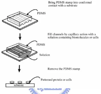
(12) which is not available in most bio-labs. In this study, we propose a novel technique i.e. open-top SU-8 microfluidic channel, which can not only generate micro protein patterns for guiding neuron outgrowth, but also solve the forgoing problem to integrate micro protein patterns with microelectronic device of microelectrode array (MEA) without any aids of special setup.. 1.2 Related Researches 1.2.1 Patterning by Microfluidic Networks Kim et al. [5] developed a technique called micromolding in capillaries (MIMIC) for fabricating three-dimensional structures by allowing solutions to flow into microfluidic channels formed by bringing a PDMS (Polydimethylsiloxane) mold into conformal contract with a substrate. MIMIC is not restricted to patterning curable prepolymers, and has also been used to pattern a wide variety of materials such as precursor polymers to glassy carbon or ceramics, sol-gel materials, inorganic salts, polymer beads, and colloidal particles. Delamarche et al. [6] extended MIMIC to the patterning of biological molecules such as immunoglobulins. They patterned biomolecules with submicron resolution on a variety of substrates including gold, glass, and polystyrene, by allowing solutions of the biomolecules to flow through microfluidic channels. Folch et al. [7] also used microfluidic channels to produce patterns of cells on biocompatible substrate. They created proteins templates on surface by the adsorption of proteins from solutions that were passed through elastomeric channel that is made by PDMS. Micropatterns of collagen or fibronectin were used to cause cells to adhere 2.
(13) selectively on various biomedical polymers and on heterogeneous or microtextured substrates. On removing the elastomeric stamp, the bare substrate areas could be seeded with more adhesive cell type such as fibroblasts, thereby producing micropatterned co-cultures. By allowing different cell suspensions to flow through different microchannels, patterns of cells could be generated on surface (Figure 1.1 and 1.2).. Figure 1.1 Illustration of the procedure used to pattern proteins using microfluidic channels. [1]. Figure 1.2 Generating micropatterns on various polymers by MIMIC. (Scale bar is 50µm) [7] 3.
(14) 1.2.2 Neural Guidance by Microfluidic System Martinoia et al. [8] presented a low-cost and simple technique based on the hydraulically driven deposition of adhesion molecules (Figure 1.3) for patterning populations of neurons on microfluidic system of silicon micromachined substrates (Figure 1.4).. Figure 1.3 Setup of flow-through chamber for the deposition of adhesive proteins. [8]. Figure 1.4 (a) A particular of pit and channels of micromachined substrate. (b) Populations of spinal cord neurons patterned on a silicon microstructure. [8]. Griscom et al. [9] developed a fabrication technique for three-dimensional high-aspect-ratio micro-walls of PDMS membrane for biological cell patterning and single-neuron guidance. In this work, three-dimensional micro-molds are made directly 4.
(15) on silicon wafers using inductively coupled plasma reactive ion etching (ICP-RIE), and also using multi-level SU-8 negative photoresist (Figure 1.5). Cell placement is achieved through an array of 50µm square holes in a 150-100µm thick PDMS membrane, which is placed on a glass substrate. Vertical holes in the membrane are linked by horizontal tunnels on the glass side of the membrane, for use in neural guidance or delivery of drugs or nutrients. The effectiveness of the membrane for cell placement, growth and guidance was tested using fluorescent yeast cells and PC12 neural cells (Figure 1.6).. Figure 1.5 Fabrication process for micro-mold by (a) ICP-RIE of silicon etching, and (b) multi-level SU-8 [9]. Figure 1.6 PC12 cell along the walls of the microfluidic channel after 24h in culture. [9] 5.
(16) 1.2.3 Protein Patterning on Microelectronic Device As mentioned before, it is difficult to transfer the micro protein patterns on microelectronic device by the common patterning methods such as µCP and MIMIC without any aids of special setups. Lars Lauer et al. [4] presented a special setup, which solved the problem of transferring micro protein patterns on microelectronic device of MEA. The setup was under microscopic control through microscope and prism to perform fine alignment between micro protein patterns and microelectrode (recording) device of MEA for detecting neuron electrical activity (Figure 1.7 and 1.8). By the fine alignment, neuron would be guide along the protein patterns to the sensitive recording spot.. Figure 1.7 Schematic sketch of the setup for aligned microcontact printing. [4]. Figure 1.8 Protein grid patterns aligned to the microelectrodes. [4] 6.
(17) 1.3 Objectives In this study, we propose a new technique, i.e. open-top SU-8 microfluidic channel, to generate micro protein patterns of laminin for neural guidance; and to integrate the micro protein patterns with microelectronic device of MEA for related researches of fundamental studies in biology, biosensors technology, and tissue engineering applications. For protein patterning, flows of laminin solutions were restricted by open-top SU-8 microfluidic channel to finish protein patterning, and using open-top SU-8 microfluidic channel can prevent salt crystals precipitating from the buffer solution by micro scale evaporation. The complete micro protein patterns were performed by using open-top SU-8 microfluidic channel. For neuron culture, using the “open-top” microfluidic channel without cover, protein and medium loading before experiment and cleaning after experiment become more convenient and faster, that is easier for medium to transfer into the neural cell and prevents neurons from lacking the sufficient trophic factors to survive. Since there is no cover over the top of the microchannel system, we needn’t any fluorescent material for observation of neurons outgrowth. For neuron guidance, the neurons surface of integrins can adhere to the laminin and grow along the micro protein patterns. Using open-top SU-8 microfluidic channel can provide a topographical confinement for neural guidance successfully. For integration ability, the micromachined open-top SU-8 microfluidic channel can integrate microelectronic device of MEA into the microfluidic channels to achieve the “self-alignment” of micro protein patterns with microelectronic devices. Using micromachined open-top SU-8 microfluidic channel can solve the problem of transferring micro protein patterns on microelectronic device. 7.
(18) 1.4 Infrastructure This thesis is divided into six chapters. In Chapter 1, motivation, related researches, and our objectives are described. In Chapter 2, the design concepts and fabrication methods of open-top SU-8 microfluidic channel system for neural guidance are described, and the integration of open-top SU-8 microfluidic channel with microelectronic device is presented. In the Chapter 3, the category of neural cell and culture method are introduced. In the Chapter 4, observations of neuron outgrowth in open-top SU-8 microfluidic channel are recorded. In the Chapter 5, unusual points and details of this study are discussed. Finally, conclusions and prospects are proposed in Chapter 6.. 8.
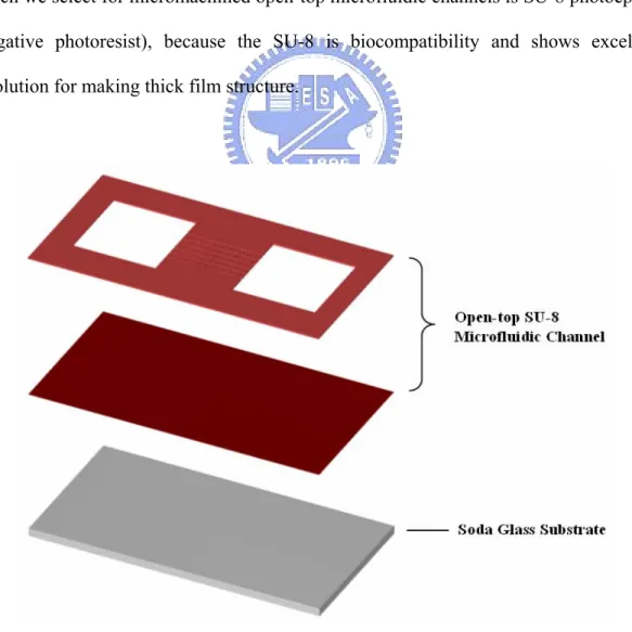
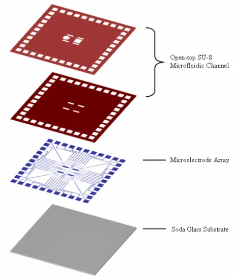
(19) Chapter 2 Design and Fabrication 2.1 Open-Top SU-8 Microfluidic Channel System 2.1.1 Concept Design Our concept design of open-top SU-8 microfluidic channel device can be divided into three micromachined layers that are soda glass for substrate and two SU-8 layers for main structure of microfluidic channel system (Figure 2.1). About the SU-8 microfluidic channel system, it consists of two protein tanks for neural cell explants, and six channels for neural guidance (Figure 2.2). The material which we select for micromachined open-top microfluidic channels is SU-8 photoepoxy (negative photoresist), because the SU-8 is biocompatibility and shows excellent resolution for making thick film structure.. Figure 2.1 Three layers of open-top SU-8 microfluidic channel device. 9.
(20) Figure 2.2 Layout and dimensions of open-top SU-8 microfluidic channel with two protein tanks and six channels.. 2.1.2 Layout of Open-Top Microfluidic Channel The layout and dimensions of open-top SU-8 microfluidic channel including two protein tanks and six channels are illustrated in Figure 2.2. The dimension of both protein tanks is 1000 × 1000 µm2. One of the protein tanks is used for injecting laminin solution and explanting neural cells, and the other one is used for storing the redundant laminin solution after filling six channels. The microchannel is 4µm or 10µm wide and consists of 20 × 20 µm2 nodes with 100µm interval. In our design, there are eight types of microfluidic channel patterns as showed in Figure 2.3.. Figure 2.3 Various types of micro channel patterns. 10.
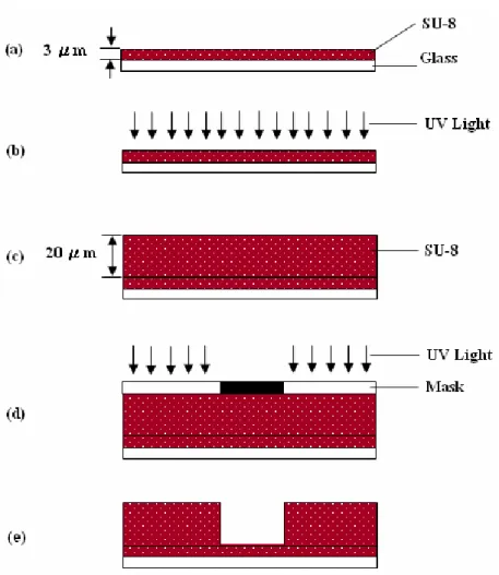
(21) 2.1.3 Fabrication of Open-Top Microfluidic Channel The micromachined fabrication processes for open-top SU-8 microfluidic channel, which include five steps and use one mask, are illustrated in Figure 2.4.. Figure 2.4 Micromachined fabrication processes of open-top SU-8 microfluidic channel.. In our designed fabrication processes, soda glass wafer is clean up by sulfuric acid and de-ionized water, initially (Figure 2.4a). Then the 3µm thick SU-8 is coated on glass substrate and exposed to UV light broadly to form the bottom structure of microchannel (Figure 2.4b). Afterward, the 20µm thick SU-8 is coated on previous 3µm SU-8 layer (Figure 2.4c) and then conventional photolithograph process was performed to define the open-top SU-8 microfluidic channel system (Figure 2.4d). After development and 11.
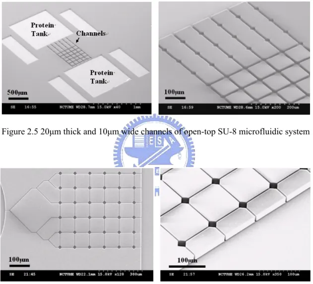
(22) hard bake at 200℃ for 30min, the open-top SU-8 microfluidic channel system is finished and prepared for neural guidance (Figure 2.4e). The scanning electron microscope (SEM) images of the finished open-top SU-8 microfluidic channel are shown in Figure 2.5 and Figure 2.6.. Figure 2.5 20µm thick and 10µm wide channels of open-top SU-8 microfluidic system. Figure 2.6 20µm thick and 4µm wide channels of open-top SU-8 microfluidic system. In the micro fabrication of open-top microfluidic channel, the channel structures with 20µm high and 4µm wide are not easy to fabricate without a high performance and straight light source from aligner in exposure process.. 12.
(23) 2.2 Integration of Microelectronic Device into Microfluidic Channel System 2.2.1 Concept Design of Integration In our concept design, the micromachined open-top SU-8 microfluidic channel system can integrate microelectronic device of MEA into the microfluidic channels to achieve self-alignment between micro protein patterns and microelectronic device. As illustrated in Figure2.7, it shows the integration of micromachined open-top SU-8 microfluidic channel with MEA.. Figure 2.7 Micromachined open-top SU-8 microfluidic channel with MEA. 13.
(24) 2.2.2 Introduction and Layout of MEA H. Ecken et al. [10] showed the 8 ¯ 8 MEA system for the recording of activity signals (Figure 2.8). The advantages of MEA recording technique are long-term, multisite and continuous recording of extracellular signals from neurons in close to microelectrodes. Besides recoding signals, MEA also can offer electric current to stimulate the neuron growth.. Figure 2.8 Recording system of 8 ¯ 8 microelectrode array. [10]. Our design for the microelectronic device of MEA consists of thirty-six gold micro-electrodes (6 ¯ 6 array, Figure 2.9), and the MEA is buried under nodes of open-top SU-8 microfluidic channel. The virtual close-up picture of open-top SU-8 microchannel with MEA is showed in Figure 2.10.. Figure 2.9 Geometry of microelectrode array. 14.
(25) Figure 2.10 Virtual close-up picture of open-top SU-8 microchannel with MEA.. 2.2.3 Fabrication of Open-Top Microfluidic Channel with MEA Our designed fabrication flowchart for integration of open-top SU-8 microfluidic channel with MEA is illustrated in Figure 2.11.. Figure 2.11 Fabrication flowchart of open-top SU-8microfluidic channel with MEA. 15.
(26) Initially, soda glass wafer is cleaned up by sulfuric acid and de-ionized water (Figure 2.11a). Then, the 2µm positive photoresist of FH-6400L is coated on glass substrate, and exposed to UV light for patterning MEA mold by mask #1 (Figure 2.11b, Figure 2.12 and Figure 2.13).. Figure 2.12 Three masks for fabrication of open-top microfluidic channel with MEA.. Figure 2.13 O.M. picture of 2µm FH-6400L on glass substrate for MEA mold. 16.
(27) Next, 200Å titanium as adhesive layer was sputtered on FH-6400L before 500Å gold sputtering on titanium (Figure 2.11c). After sputtering, the glass wafer was immersed into acetone to lift off the FH-6400L photoresist to form MEA of gold patterns on glass substrate (Figure 2.11d and Figure 2.14).. Figure 2.14 O.M. picture of finished MEA of 200Å Ti/500Å Au after lift-off process.. 17.
(28) Then, the soda glass substrate with MEA is coated on 3µm thick SU-8 and exposed to UV light by mask #2 to form insulated layer (bottom structure of microchannel) against short of MEA (Figure 2.11e, Figure 2.12 and Figure 2.15).. Figure 2.15 O.M. picture of 3µm SU-8 for insulated layer on MEA.. 18.
(29) Afterward, the 20µm thick SU-8 is coated on previous 3µm insulated layer and mask #3 was performed to define the open-top SU-8 microfluidic channel system. Through development and hard bake at 200℃ for 30min, the fabrication of open-top SU-8 microfluidic channel with MEA is finished (Figure 2.11f, Figure 2.12, Figure 2.16 and Figure 2.17).. Figure 2.16 O.M. picture of 20µm thick and 10µm wide open-top SU-8 microfluidic channels with MEA. 19.
(30) (a) Focus on top.. (b) Focus on bottom. Figure 2.17 O.M. picture of 20µm thick and 4µm wide open-top SU-8 microfluidic channels with MEA.. After dicing of the glass wafer, the integration device of open-top SU-8 microfluidic channel with MEA is complete as showed on Figure 2.18.. Figure 2.18 Complete open-top SU-8 microfluidic channels with MEA after dicing. 20.
(31) The prototype open-top SU-8 microfluidic channel with MEA for extracellular signal recording from neuron in vitro is showed in the Figure 2.19.. Figure 2.19 Prototype open-top SU-8 microfluidic channel with MEA for extracellular signal recording.. 21.
(32) Chapter 3 Cell Culture 3.1 The Mechanism of ECM for Patterned Cells In vertebrates and invertebrates many peripheral axons grow through connective tissue or along basal laminae. These patterns were initially thought to result from preferential extension through channels or along hard surfaces. Simple studies of outgrowth in vitro were instrumental in revising this view. For example, when neurons were grown on patterned substrates (i.e. stripes of one substance alternating with patches of a second), the axons extended preferentially along pathways of the more adhesive substrate, even when the less adhesive substance was quite capable of supporting neurite outgrowth on its own, as illustrated in Figure 3.1, growth cone extends only on the collagen-coated surface. We now know that axonal preferences correlate only imperfectly with adhesiveness, but the main point stands: growing axons recognize molecular difference among the substrates along which they grow, and these distinctions can regulate the direction and rate of their growth. [11]. Figure 3.1 The growth cone extension on an extracellular matrix component. [11]. Numerous substances capable of promoting outgrowth in vitro have now been identified, including laminin, collagens, fibronectin, and some proteoglycans, and the 22.
(33) laminin, collagens, fibronectin, and some proteoglycans are components of ECM.. Figure 3.2 Laminins in basal laminae interact with integrins on growth cones. [11]. Axons recognize growth-promoting molecules in the ECM by integrins in neural surface. A variety of matrix-binding proteins have been isolate from neural cells, but the main signaling receptors appear to be the integrins and integrins are heterodimers of α and β subunits, drawn from a set of at least 16α and 8β chains. Essentially all cells in the body bear at least one integrin, and some express several. Each dimer recognizes a distinct set of ligands — α1β1, for example, binds to collagens and laminins, α4β1 binds to fibronectin, and so on. At least seven different integrin heterodimers bind to laminins, but they differ in the laminin isoforms they prefer and the domains on laminin that they recognize (see Figure 3.2, laminins are major components of basal laminae and account for much of the axon outgrowth-promoting ability of the ECM. Laminins are cruciform heterotrimers of related α, β, and γ subunits, drawn from a family of at least 5α, 4β, and 3γ genes.) Together, the multiplicity of integrins and matrix components provides the 23.
(34) potential for considerable subtlety and specificity in the interactions of growth cones with the ECM. [11] To sum up the foregoing, ECM molecules promote neuron outgrowth and integrins are matrix-binding proteins in nerve cell.. 3.2 Retinal Ganglion Cells of Goldfish The experimental neurons which we select for this study are retinal ganglion cells (RGCs) derived from goldfish (Figure 3.3). The RGCs of goldfish are easier for culture in vitro at room temperature, because the goldfish is poikilothermal animal. Unlike mammalian (human) RGCs, the injured RGCs of goldfish have powerful capacity to regenerate their axon. When optic nerve of goldfish is crushed, even cut, RGCs in the eye regenerate their connection to the brain. The RGCs provide a model for the study of neural re-growth and neuro-plasticity; so most studies of central nervous system (CNS) regeneration have utilized the goldfish visual system. Understanding the control of axon growth and regeneration is potential importance in devising approach to regeneration of damaged axon in humans. [12]. Figure 3.3 Retinal ganglion cells of goldfish. [12] 24.
(35) 3.3 Cell Culture of RGCs The device of open-top SU-8 microfluidic channel which we made in Chapter2 (Figure 2.5 and Figure 2.6) is prepared for study of neural guidance of RGCs. Before cell culture in open-top SU-8 microfluidic channel, the open-top SU-8 microfluidic channel should be immersed into 45% ethanol solution for sterilizing and cleaning. The material property of SU-8 is hydrophobic, so the open-top SU-8 microfluidic channel should be treated with O2 plasma (Figure 3.4a) for ten seconds to change SU-8 surface property into hydrophilic to ensure that the protein liquid can enter into microchannels to achieve micropatterns generation.. Figure 3.4 The flowchart of cell culture.. 25.
(36) After sufficient hydrophilic treatment of open-top SU-8 microfluidic channel by O2 plasma (Figure 3.4a), the 0.5µl laminin solution (50µg/ml laminin in PBS) is injected into one of the protein tanks and the laminin solution tends to flow from protein tank into microchannel by corner flow (Figure 3.4b). Until tanks and microchannels filling with laminin solutions (Figure 3.5), the device of open-top SU-8 microfluidic channel with laminin will be immersed in Leibovitz’s L-15 medium (Figure 3.4c).. Figure 3.5 Open-top SU-8 microfluidic channel system fills with laminin solution.. 26.
(37) Then, the 450 × 450 µm2 piece of RGCs of goldfish will be prepared and explanted on the protein tank of open-top SU-8 microfluidic channel (Figure 3.6). Finally, the culture dish will be stored at the environment of 25℃ (Figure 3.4d).. Figure 3.6 RGCs are explanted on protein tank of open-top SU-8 microfluidic channel.. 27.
(38) Chapter 4 Results In this study, culture and observation of RGCs of goldfish were performed in three different dimensions of open-top SU-8 microfluidic channel, including 20µm high and 10µm wide channel, 20µm high and 4µm wide channel, and 10µm high and 10µm wide channel. According to our observation, the lifetime of RGCs was about three days, if we didn’t change and add any medium of Leibovitz’s L-15. After three days of RGCs culture, axons of RGCs drew back and they were on the verge of death. This is mainly due to the fact that RGCs lacked the sufficient trophic factors from medium to survive. Besides, RGCs can’t be survived during the explanting process of RGCs on the protein tank if the RGCs square piece didn’t attach to laminin patterns or attached to laminin patterns by wrong side of RGCs square piece.. 4.1 Axon Growth in 20µm high and 10µm wide channel Figure 4.1a and Figure 4.1c illustrated axons of RGCs outgrowth readily in open-top SU-8 microfluidic channel with 20µm high and 10µm wide after 24 hours and after 48 hours, respectively. In the Figure 4.1a, 24 hours after RGCs explanting, some of the pioneering axons, which were marked by white arrows, grew following the laminin patterns and the wall into open-top SU-8 microfluidic channels. The close-up picture of part of Figure 4.1a was illustrated as Figure 4.1b. In the Figure 4.1c, 48 hours after RGCs explanting, several pioneering axons grew straightly towards open-top microfluidic channels. Furthermore, the newborn axons of RGCs tended to be attached along the previous pioneering axons for growth. 28.
(39) (a). (b). (c) Figure 4.1 Axons of RGCs outgrowth in open-top SU-8 microfluidic channel with 20µm high and 10µm wide. (a) After 24 hours. (b) Close-up of (a). (c)After 48 hours. 29.
(40) We also observed an interesting phenomenon that the axon turned into a corner by crossing with open-top SU-8 microchannels in Figure 4.2b. That was caused by the corner flow of laminin solutions. Laminin solutions piled up on corners, so axons grew along corners and turned into a corner by crossing with open-top SU-8 microfluidic channel of 20µm high and 10µm wide. In this study, we call this phenomenon “corner effect”.. (a). (b) Figure 4.2 Axons of RGCs outgrowth in open-top SU-8 microfluidic channel with 20µm high and 10µm wide. (a) After 24 hours. (b) After 48 hours. 30.
(41) 4.2 Axon Growth in 20µm high and 4µm wide channel The width of open-top microfluidic channel was reduced down from the original design of 10µm to 4µm wide line width (Figure 4.3).. (a). (b) Figure 4.3 (a) Axons of RGCs outgrowth in open-top SU-8 microfluidic channel with 20µm high and 4µm wide after 48 hours. (b) Close-up of (a). 31.
(42) In the Figure 4.3a, 48 hours after RGCs explanting, several axons still grew straightly into open-top microfluidic channels that were marked by white arrows. It was also obvious in this figure that newborn axons of RGCs tended to be attached along the previous pioneering axons for growth. In the Figure 4.3b, the close-up of block diagram as illustrated in Figure 4.3a, shows the width of axon is about 2~3µm and the axons outgrowth by confinement in open-top SU-8 microchannel with 4µm wide and 20µm high. Comparing with previous dimensions of 10µm wide and 20µm high, the 4µm wide microchannel seems better for confining axons growth straightly without corner phenomenon that mentioned in Figure 4.2.. 4.3 Axon Growth in 10µm high and 10µm wide channel The thickness of the wall of open-top microfluidic channel was reduced from the original design of 20µm high to 10µm high in the Figure 4.4 for control group. In the Figure 4.4a, 48 hours after RGCs explanting, several axons still grew along protein patterns into open-top microfluidic channels that were marked by white arrows, but some axons grew over the wall that were marked by bold black arrow. It was quite obvious in this figure that newborn axons of RGCs tended to be attached along the previous pioneering axons for growth. In the Figure 4.4b, the close-up of block diagram as illustrated in Figure 4.4a, showed the axon growth out of the microfluidic channel with 10µm high that were marked by black arrow. It seemed that the channel structure with 10µm high is too low to confine axon outgrowth.. 32.
(43) (a). (b) Figure 4.4 (a) Axons of RGCs outgrowth in open-top SU-8 microfluidic channel with 10µm high and 10µm wide after 48 hours. (b) Close-up of (a).. Comparing with previous two dimensions that mentioned in section 4.1 and 4.2, the result show that the 20µm high wall of open-top SU-8 microchannel behaves a rather good role to confine axon outgrowth then 10µm high.. 33.
(44) Chapter 5 Discussion Up to now, we have demonstrated the integration ability of open-top SU-8 microfluidic channel with microelectronic device of MEA in Chapter 3, and the neural guidance ability of RGCs in open-top SU-8 microfluidic channel in Chapter 4. In this chapter, we will discuss more details about driving force and micro scale evaporation in open-top SU-8 microfluidic channel.. 5.1 Driving Force for Protein Patterning The most special characteristic of open-top SU-8 microfluidic channel is using “open-top” microchannel to guide neuron. Different from the traditional enclosed microchannels, open-top SU-8 microfluidic channel does not employ the capillarity. Since there is no cover over the top of the microchannel system, the selection of material for open-top microfluidic channel is important. We select SU-8 for the main structure material of open-top microfluidic channel in this study, because the surface property of SU-8 can be transformed from hydrophobic to hydrophilic by O2 plasma. After sufficient hydrophilic treatment of open-top SU-8 microfluidic channel by O2 plasma, the fluid of laminin solution can be driven in “open-top” microchannel by corner effect. So the micro protein patterns can be generated by “open-top” microfluidic channels conforming to the shape of open-top SU-8 microfluidic channel.. 5.2 Micro Scale Volume Evaporation In micro scale volume, liquid is easy to lose by evaporation. Solutes will precipitate and micro protein patterns will be destroyed, when solvents evaporate. The “open-top” SU-8 microfluidic channel also has this problem (Figure 5.1), but this 34.
(45) problem also can be prevented by using open-top SU-8 microfluidic channel.. Figure 5.1 Salt crystals precipitate from the buffer solution by micro scale evaporation.. 35.
(46) Generally speaking, the precipitated salt crystals were come from the buffer solutions and fluorescent materials by micro scale evaporation. Generating micro protein patterns by open-top SU-8 microfluidic channel needn’t add any fluorescent material into laminin solution for label to observe neurons outgrowth, so the precipitated salt crystals from fluorescent materials can be prevented. The salt crystals precipitating from the buffer solution of phosphate buffered saline (PBS) also can be prevented by a trick. Before solvents evaporation, the laminin patterned open-top SU-8 microfluidic channel will be immersed into Leibovitz’s L-15 medium immediately. Using this trick, salt crystals of buffer solution (PBS) can be prevented from precipitating by micro scale evaporation in open-top SU-8 microfluidic channel. Finally, the complete micro protein patterns will be performed by using open-top SU-8 microfluidic channel without any loss.. 36.
(47) Chapter 6 Conclusions Open-top SU-8 microfluidic channel, as we propose in this study, requires only a small volume (~0.5µl) of laminin solution to fill the two tanks and six microchannels. Through sufficient hydrophilic treatment of SU-8 microchannel structure, it can drive the fluid of laminin in the “open-top” SU-8 microchannels by corner flow. The micro protein pattern can be generated by “open-top” microfluidic channels when laminin solutions fill microchannels and conform to the shape of open-top SU-8 microfluidic channel. After laminin patterning, the micro protein patterns have been prepared for neural culture and axon guidance. Culture of retinal ganglion cells (RGCs) are performed using injured goldfish in this study, because the goldfish is poikilothermal animal and the RGCs of goldfish is easier for culture and observation in vitro at room temperature. In Chapter 4 of this study, the experimental results show axons outgrowth readily in microchannels and verify the open-top SU-8 microfluidic channel is effective for neural guidance by the 20µm high wall. Another characteristic of the micromachined open-top SU-8 microfluidic channel is its ability to integrate microelectronic device of MEA into the microfluidic channels to in order achieve the “self-alignment” between micro protein patterns and microelectronic devices of MEA. Open-top SU-8 microfluidic channel shows good performance to generate micro protein patterns for axon guidance and good ability to integrate microelectronic device of MEA into the microfluidic channels. Open-top SU-8 microfluidic channel is a new selection for related researches of neural guidance in fundamental studies, biosensors technology, and tissue engineering 37.
(48) applications. In the future, we expect to finish extracellular signal recording from neuron in vitro using the device of open-top SU-8 microfluidic channel with MEA.. 38.
(49) Reference [1] Ravi S. Kane, Shuichi Takayama, Emanuele Ostuni, Donald E. Ingber, George M. Whitesides, “Patterning proteins and cells using soft lithography”, Biomaterials 20 (1999) 2363-2376 [2] D. R. Jung, R. Kapur, T. Adams, K. A. Giuliano, M. Mrksich, H. G. Craighead, and D. L. Taylor, "Topographical and Physicochemical Modification of Material Surface to Enable Patterning of Living Cells”, Critical Reviews in Biotechnology 21(2001) 111-154 [3] Helga Sorribas, Celestino Padeste, Louis Tiefenauer, “Photolithographic generation of protein micropatterns for neuron culture applications”, Biomaterials 23 (2002) 893-900 [4] Lars Lauer, Seven Ingebrandt, Martin Scholl, and Andreas Offenhaäusser, “Aligned Microcontact Printing of Biomolecules on Microelectronic Device Surfaces”, IEEE Transactions on Biomedical Engineering, Vol.48, No.7, July 2001 [5] Enoch Kim, Younan Xia, George M. Whitesides, “Polymer microstructures formed by molding moulding in capillaries”, Nature 1995, 376:581-584 [6] Emmanuel Delamarche, André Bernard, Heinz Schmid, Bruno Michel, Hans Biebuyck, “Patterned Delivery of Immunoglobulins to Surfaces Using Microfluidic Networks”, Science 1997, 272:779-781 [7] Albert Folch, Mehmet Toner, “Cellular Micropatterns on Biocompatible Materials”, Biotechnol. Prog. 1998, 14, 388-392 [8] Sergio Martinoia, MarcoBovea, Mariateres Tedesco, Benno Margesin, Massimo Grattarola, “A simple microfluidic system for patterning populations of neurons on silicon micromachined substrates”, Journal of Neuroscience Methods 87 (1999) 35–44 39.
(50) [9] Laurent Griscom, Patrick Degenaar, Bruno LePioufle, Eichi Tamiya and Hiroyuki Fujita, “Cell Placement and Neural Guidance Using a Three-Dimensional Microfluidic Array”, Jpn. J. Appl. Phys. Vol. 40 (2001) pp. 5485–5490 [10] H. Ecken, S. Ingebrandt, M. Krause, D. Richter, M. Hara, A. Offenhaeusser, "64-Channel extended gate electrode arrays for extracellular signal recording", Electrochimica Acta 48 (2003) 3355-3362 [11] Eric R. Kandel, James H. Schwartz, Thomas M. Jessell, “Principles of neural science”, 4th Ed. McGraw-Hill, New York 2000 [12] 何佳霖,“圖形式細胞培養在生命科學研究之應用”,國立陽明大學,碩士論 文,民國 91 年. 40.
(51)
數據
![Figure 1.3 Setup of flow-through chamber for the deposition of adhesive proteins. [8]](https://thumb-ap.123doks.com/thumbv2/9libinfo/8116837.165752/14.892.154.744.359.900/figure-setup-flow-chamber-deposition-adhesive-proteins.webp)
![Figure 1.5 Fabrication process for micro-mold by (a) ICP-RIE of silicon etching, and (b) multi-level SU-8 [9]](https://thumb-ap.123doks.com/thumbv2/9libinfo/8116837.165752/15.892.133.767.480.761/figure-fabrication-process-micro-silicon-etching-multi-level.webp)
![Figure 1.7 Schematic sketch of the setup for aligned microcontact printing. [4]](https://thumb-ap.123doks.com/thumbv2/9libinfo/8116837.165752/16.892.203.685.548.800/figure-schematic-sketch-setup-aligned-microcontact-printing.webp)
+7

![Figure 2.8 Recording system of 8 ¯ 8 microelectrode array. [10]](https://thumb-ap.123doks.com/thumbv2/9libinfo/8116837.165752/24.892.217.682.412.716/figure-recording-microelectrode-array.webp)
相關文件
The picture below shows how the cortisol levels rise and fall during the day.. From the news, which is a good time
Promote project learning, mathematical modeling, and problem-based learning to strengthen the ability to integrate and apply knowledge and skills, and make. calculated
A good way to lead students into reading poetry is to teach them how to write their own poems.. The boys love the musical quality of
Students read the adapted version of the fable “The Lion and the Mouse” to learn to be grateful and the English saying of wisdom “One good turn deserves another.” Teachers
- strengthening students’ ability to integrate and apply knowledge and skills (including skills related to hands-on experiences) within and across the KLAs of Science, Technology
NETs can contribute to the continuing discussion in Hong Kong about the teaching and learning of English by joining local teachers in inter-school staff development initiatives..
According to the passage, which of the following can help facilitate good sleep for children.. (A) Carefully choose the online content
• To achieve small expected risk, that is good generalization performance ⇒ both the empirical risk and the ratio between VC dimension and the number of data points have to be small..
