Yet-Ran Chen Mei-Chun Tseng Guor-Rong Her
Department of Chemistry, National Taiwan University, Taipei, Taiwan, R.O.C
Design and performance of a low-flow capillary
electrophoresis-electrospray-mass spectrometry
interface using an emitter with dual beveled edge
A low-flow electrophoresis-mass spectrometry (CE-MS) interface has been developed for interfacing capillary zone electrophoresis (CZE) with electrospray- ionization-mass spectrometry (ESI-MS). The interface consists of two parallel capillary columns (a separation column and a makeup column), and an emitter with a dual beveled edge. While maintaining a relatively low optimum flow rate, the dual-beveled-edge ESI emitter allows the use of a tip with larger orifice. Therefore, this interface is less prone to column blocking in comparison with a flat tip. Primarily attributed to low sample dilution and smaller initial droplet, the interface showed better sensitivity than a con-ventional sheath liquid interface. Furthermore, the interface was found to be more resistant to the presence of nonvolatile salts. By using 40 mM borate and 20 mMa-cyclodextrin (a-CD) as the running buffer, four major forms of gangliosides were detected by CE-MS.
Keywords: Capillary zone electrophoresis/ Ganglioside / Low-flow interface / Mass spectrometry /
Nonvolatile buffer DOI 10.1002/elps.200410159
1 Introduction
With the increasing availability of electrospray-mass spectrometry (ESI-MS) [1–4], the interest to interface this ionization technique with liquid-based separation has also increased. An important area of ESI-MS interfacing is with capillary electrophoresis (CE) [5, 6], a combination that offers fast and high-resolution separations, as well as sensitive and information-rich detection. The most common way of interfacing CE to ESI-MS is through the use of a liquid sheath, first demonstrated by Smith and co-workers [7]. The sheath liquid interface is widely used because of its relative ease of implementation and versa-tility. The sheath liquid provides electrical contact with the outlet end of the separation capillary and allows CE-ESI-MS operation with a wide range of buffer systems [8–10]. Although the sheath liquid interface has facilitated the progress in CE-ESI-MS, it does have some limitations. One of the major drawbacks in conventional sheath liquid interface is that the addition of sheath liquid in the inter-face can degrade sensitivity since the analyte band is diluted considerably by the high flow rate of the sheath liquid (several microliters per minute). Another common CE-MS interface is the sheathless interface [11–22]. In
this interface, several approaches have been proposed to maintain the electrical continuity of the electrophoresis circuit, including the application of a conductive coating, connecting to a stainless steel tip, and the use of a liquid junction [14–22]. The major benefit of this design is that the sample bands are not diluted. However, because the sheathless CE-ESI-MS interface uses a single capillary, several practical issues arise. A major concern is that the diameter of the tip needs to be carefully selected to maintain reasonable migration times and ESI sensitivity. If a tip with a too small orifice is used, it creates a long analysis time and the capillary can easily be blocked. On the other hand, if a tip with a large orifice is used, it pro-vides a shorter analysis time but at the cost of a stable spray and sensitivity [14]. Another disadvantage of sheathless interface is that it is often difficult to find a buffer solution optimized for both CE separation and ESI ionization efficiency. Therefore, the selection of running buffer is rather limited.
After considering the merits and limitations of the two types of the interface, a better CE-ESI-MS interface would combine the versatility of the liquid sheath design with the sensitivity of the sheathless format. A reasonable alternative is an interface which incorporates a low flow rate makeup liquid. Because of less dilution, the sensitiv-ity of a low flow interface (several hundred L/min) would be better than that of a conventional sheath liquid inter-face. Recently, we have developed a low-flow sheath liquid interface using a sprayer having an orifice of Correspondence: Dr. Guor-Rong Her, Department of Chemistry,
National Taiwan University, Taipei, Taiwan, R.O.C E-mail: [email protected]
Fax: 1886-2-2368058
reduced diameter [23]. A smaller orifice sprayer was used because it is known that the optimum flow rate decreases with orifice diameter. The advantage of using a sprayer with smaller orifice was that it lowered the optimal flow rate and thus reduced the sample dilution. Improved sensitivity was achieved in comparison with a conven-tional sheath liquid interface [23]. However, the interface is relatively easy to be clogged because of the small orifice (25 mm). Great care must be taken to eliminate small particles from sample and buffer solution.
In the improvement of a sheathless CE-MS interface, we have shown that a 75 mm beveled sprayer has a similar optimum flow rate as a 25 mm flat tip [14]. While main-taining a similar optimum flow rate and consequently similar sample dilution, a 75 mm beveled emitter is more rugged and durable than a 25 mm flat tip because of the larger inner and outer diameters. The better performance of the 75 mm beveled emitter was mainly due to the sharp tip of the emitter. Several groups [24–28] have shown that the shape of the emitter played an important role in the electrospray. The performance of the electrospray could be improved simply by sharpening the tip rather than using a pulled tip [24–26]. Recently, Le Gac et al. [27] reported that the nanoelectrospray could be achieved by the use of planar nib-like emitter. Liu et al. [28] also reported a new type of microelectrospray emitter using a pointed carbon fiber.
In this paper, a new low-dilution interface is proposed in which two columns (a separation and a makeup column) were used and both columns were tapered, beveled, and combined. The resulting dual beveled edge emitter is expected to have a small tip. Because of the small emitter tip, a low optimum flow rate and thus less sample dilution is expected. In addition, the tip would be less likely to be clogged because of the larger orifice in com-parison with a flat tip. Successful applications are pre-sented to demonstrate the utility of this interface in CE-MS operation.
2 Materials and methods
2.1 Reagents
2-(N-Cyclohexylamino)ethanesulfonic acid (CHES) and ganglioside type III (purified from bovine brain containing approximately 20% N-acetylneuraminic acid) were pur-chased from Sigma (St. Louis, MO, USA). a-CD was obtained from Nacalai Tesque (Kyoto, Japan). 4-Nitro-phenol (4-NP), 2,4-dinitro4-Nitro-phenol (2,4-DNP), 2-methyl-4,6-dinitrophenol (2-M-4,6-DNP), 2,4,6-trichlorophenol (2,4,6-TCP), and pentachlorophenol (PCP) were
pur-chased from Fluka (Buchs, Switzerland). Anhydrous sodium tetraborate was purchased from Janssen Chi-mica (Beeise, Belgium). Ammonium acetate, methanol, and isopropyl alcohol (IPA) of HPLC-grade were pur-chased from J. T. Baker (Phillipsburg, NJ, USA) and used without further purification. Deionized water (Milli-Q water system; Millipore, Bedford, MA, USA) was used for the preparation of the samples and buffer solution.
2.2 Preparation of the beveled tapered CE capillary tip
Briefly, the 50 mm ID and 365 mm OD fused-silica capillary (Polymicro Technologies, Phoenix, AZ, USA) was drawn manually using a vertically suspended section of capillary to which a small weight (45 g) had been attached. The capillary was slowly heated to the melting stage and then quickly withdrawn. This tapered tip was etched in 48% HF for a duration of 15 min. The tip was then wrapped with cellophane tape. Under the visual inspection with a microscope (SZ-ST; Olympus, Tokyo, Japan), the tip was ground to about 457 using a ceramic wafer column cutter (Agilent, Wilmington, DE, USA) as the rasp. After grinding, the tape was removed and the tip was purged with nitro-gen gas.
2.3 Fabrication of the dual-beveled-edge CE-ESI-MS interface
Two capillary columns with a tapered beveled tip were used in this interface. The separation and the makeup capillary were arranged side by side as shown in Fig. 1. The adhesive, a-cyanoacrylate (Power Ace Corporation, Tokyo, Japan), was used to bind the two tips. After 30 min, the tip was carefully smeared with the conductive epoxy (E4110; Epoxy Technology, Billerica, MA, USA). To avoid blocking the orifices, the two capillaries were flushed with nitrogen gas during the epoxy coating. After coating, the tip was heated to 1007C for a duration of 60 min. On average, it took about 2 h to fabricate an interface. The photographs of the interface before and after the con-ductive epoxy coating are shown in Fig. 1. As can be seen in Fig. 1, the shape of the tip did not change significantly after the epoxy coating. The reproducibility of tip fabrica-tion was studied by injecfabrica-tion a 40 ppm 2,4,6-trini-trophenol solution and the makeup liquid was supplied at 500 nL/min. For three different tips, the precision of the signal intensity was about 5% and the migration time was about 10%. These interfaces were functioned properly up to one week (the longest time tested) of continuous operation.
CE
and
Figure 1. Fabrication of the dual-beveled-edge CE-ESI-MS interface.
2.4 CE and ESI-MS
The CE instrument was configured in-house. Briefly, the setup consisted of a 1000R high-voltage power supply (Spellman, Plainview, NY, USA) connected to a platinum electrode in a vial containing CE buffer and operated at constant-voltage mode. One end of the separation capillary was inserted into the CE buffer, and the other end was fabricated as part of the CE-ESI-MS interface. All MS experiments were conducted on a classical LCQ ion-trap mass spectrometer (Finnigan MAT, San José, CA, USA). The CE-ESI-MS electropherograms were acquired in selected ion monitoring (SIM) mode. A commercial x-y-z translation stage for LCQ API source (Protana, Odense, Denmark) was used for mounting the CE-ESI-MS inter-face. The position of the interface could be adjusted via the micrometer screws of the translation stage (Fig. 2). A nebulizing gas was not necessary, and the heated capil-lary was kept at a temperature of 2007C.
2.5 CE-ESI-MS analysis of phenols
The separation buffer was 20 mMCHES in aqueous solu-tion. The pH of the solution was adjusted to 10.0 with ammonia. The separation capillary was 90 cm in total length. Before each run, the separation capillary was flushed with the running buffer and equilibrated for 15 min. The makeup liquid consisted of 2-propanol, water, and ammonium hydroxide (80:20:0.5 v/v/v). The mass
trometer was operated in negative ion mode and the data were collected in SIM mode. The 40 ppm phenolic mix-ture was hydrodynamically injected into the capillary using a 15 mbar pressure differential for a duration of 15 s. The CE-ESI-MS separation was achieved by applying a potential of 20 kV and 22 kV to the sample buffer and the interface, respectively.
2.6 CE-ESI-MS analysis of gangliosides
The separation buffer was 40 mMborate and 20 mMa-CD
aqueous solution. The pH of the solution was adjusted to 10.6 with ammonia. The separation capillary was 100 cm in total length. The 4 mg/mL type III gangliosides mixture was hydrodynamically injected into the capillary using a 10 mbar pressure differential for a duration of 10 s. The makeup liquid consisted of 2-propanol, water, and ammonium hydroxide (80:20:0.5 v/v/v). The mass spec-trometer was operated in negative ion mode and the data were collected in SIM mode. The CE-ESI-MS separation was achieved by applying the potential of 20 kV and 22 kV to the sample buffer and the interface, respectively.
3 Results and discussion
3.1 Design and properties of the
dual-beveled-edge CE-MS interface
Because of smaller initial droplets, it has been shown that low-flow ESI emitters, such as microspray and nano-spray, lead to better sensitivity over ESI conducted at higher flow rates [29]. One problem with the use of a low-flow emitter as the CE-MS interface is that the emitter is relatively easy to be clogged because of the small orifice (, 25 mm). To overcome the problem of tip blocking, we have shown that, while maintaining a similar optimum flow rate as the flat tip sprayer [14], a sprayer with beveled edge could have a larger orifice than that of a flat tip. A similar optimum flow rate implies similar sample dilution and similar size of initial droplets, thus, a beveled tip emitter has a similar sensitivity as a small orifice flat emitter but is less likely to be clogged. In addition to the sample dilution and the size of initial droplet, the compo-sition of the spray solution also plays a critical role in the sensitivity of CE-MS analysis. Therefore, a CE-MS inter-face should provide the capability of controlling the final spray solution.
To meet the criteria of a sensitive and durable CE-MS interface (low sample dilution, small initial droplet, less likely of clogging, and the controlling of the final spray solution), an interface based on an emitter with dual beveled edge and a separated makeup column was
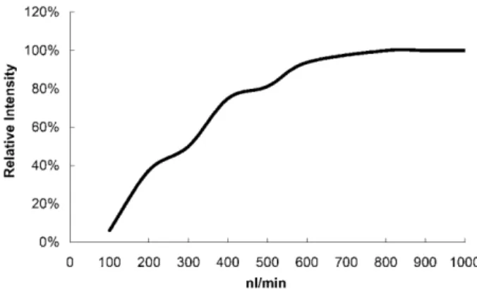
pro-posed. Both the separation and the makeup columns were tapered, bevelled, and combined. The resulting dual beveled tip interface (Fig. 1) has an optimum flow rate of about 600 nL/min (Fig. 3). Because the optimum flow rate of the interface is considerably lower than that of a con-ventional sheath liquid interface (about 3000 nL/min), smaller initial droplets were produced and sample dilution was minimized. The sprayer is less likely to be clogged because of the larger orifice (75 mm). Moreover, the makeup liquid was supplied by a syringe pump, thus the composition of the spray solution could be controlled more precisely.
Figure 3. Ion intensity versus flow rate of infusion a 1 ppm reserpine solution in MeOH:H2O = 4:1 1 0.1% acetic acid
using the dual-beveled-edge interface.
Band-broadening due to the interface is one of the major concerns in designing a CE-MS interface. The makeup liquid was supplied by the makeup column and mixed with the running buffer at the outlet of the interface. As shown in Fig. 2, the mixing volume of the interface was about the size of the Taylor cone. Thus the band-broad-ening caused by the interface could be kept to a mini-mum. Because the signal from a premixed sample was similar to that obtained with this sprayer, analyte and makeup solution were believed to be well mixed at the tip.
3.2 Performance of the dual-beveled-tip CE-ESI-MS interface
3.2.1 Analysis of phenols
To examine the performance of the interface in sensi-tivity improvement, a mixture of five phenols (40 ppm) was hydrodynamically injected into the capillary using a 15 mbar pressure differential across the capillary for a duration of 15 s. The separation buffer was 20 mM
CHES aqueous solution at pH 10. The CE separation potential was set to 20 kV and the electrospray voltage
of 22 kV was applied to the tip of the interface. The composition of the makeup liquid was 80% IPA with an addition of 0.5% NH4OH. To optimize the makeup flow,
the effect of makeup flow on analyte signals was stud-ied by injection of a 40 ppm 2,4,6-trinitrophenol solution at different makeup flow rates. As can be seen in Fig. 4, when the makeup flow rate was 0 nL/min, no electro-spray and thus no signal was observed. The sensitivity increased when the makeup flow was increased from 100 to 500 nL/min. Because of the effect of sample dilution, the sensitivity decreased when the makeup flow was higher than 500 nL/min. Under the optimum conditions, as shown in Fig. 5, the five compounds were resolved and detected in less than 15 min. On the basis of average peak heights, the dual-beveled interface was about 16-fold more sensitive than the conventional sheath liquid interface [23]. The improvement is most likely due to the low dilution factor and the smaller initial droplet. More likely due to the better controlling of the final spray solution, this interface was about four times more sensitive than the 25 mm flat-tip low-flow sheath liquid interface [23].
Figure 4. Ion intensity (by injection of a 40 ppm 2,4,6,-trinitrophenol solution) versus flow rate of makeup liquid (IPA/H2O/NH4OH = 80/20/0.5 v/v/v) using the
dual-bev-eled-edge interface.
One of the reasons for the selection of phenols as test-ing compounds is that negative ion CE-MS is often considered to be more difficult than positive ion CE-MS. In negative ion mode, the ESI onset voltage of an aqueous buffer could be higher than the onset voltage of discharge, thus discharge may occur prior to ESI. To avoid the occurrence of discharge, the ESI onset volt-age can be reduced by decreasing the surface tension of the spray solution. In this design, the surface tension of the final spray solution can be reduced by controlling the composition and the flow rate of the makeup solu-tion, thus making the interface capable of operating in negative ion mode with minimum possibility of dis-charge.
Figure 5. Mass electropherograms of a 40 ppm phenolic mixture using the dual-beveled-edge interface. The makeup liquid (IPA/H2O/NH4OH = 80/20/0.5 v/v/v) was
delivered at a flow rate about 500 nL/min.
3.2.2 Analysis of gangliosides
Nonvolatile additives (i.e., borate, phosphate, SDS, etc.) are often used in CE analysis. However, because non-volatile salts are known to reduce ionization efficiency, and also lead to ion source contamination [30], on-line coupling of CE with ESI-MS using a nonvolatile buffer is generally considered much more difficult than the cou-pling of CE using a volatile buffer. For an emitter operated at low flow rate, in addition to the improvement of sensi-tivity, the emitter was believed to have higher tolerance to nonvolatile buffers. It has been reported [31] that the larger and more lowly charged droplets (from a high-flow rate emitter) need some evaporation (and time) and thus undergo a substantial concentration increase (nonvolatile salt) before the critical surface charge density for fissions is reached, whereas smaller and highly charged droplets from the low-flow emitter would result in fissions without extensive evaporation and thus increase in nonvolatile salt concentrations. Because the interface is capable of operation at a low-flow rate, it is possible to couple CE with MS using nonvolatile salts (such as borate, phos-phate) as the separation buffers. The performance of this interface in nonvolatile buffer operation was investigated in the analysis of a ganglioside-III mixture (GD1a, GD1b, GM1, GT1b). The separation of gangliosides in CE-UV has been reported [32–34]. The best result was obtained by using 60 mM borate, 40 mM phosphate, and 20 mM
a-CD as the buffer [33, 34]. Under the optimized condi-tions, the four major forms of gangliosides (GM1, GD1a, GD1b, GT1b) were successfully separated. Unfortunately, the separation obtained in CE-UV could not be repro-duced in CE-MS using the conventional CE-MS interface, because it was observed that the highest concentration which could be tolerated by the conventional sheath liquid interface was about 10 mM borate. More volatile buffers, such as CHES, CAPS (3-(cyclohexylamino)-1-propanesulfonic acid), and ammonium acetate have been shown to be more compatible with ESI-MS. However, the resolutions achieved with these systems were not as good as that of the phosphate-borate system; the two disialoganglioside isomers, GD1a and GD1b, were co-eluted using these volatile running buffers [34].
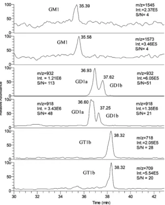
The optimum buffer concentration obtained in our CE-UV study was still too high to be handled by this dual-bev-eled-tip interface. Therefore, to find the lowest level of buffer concentration with acceptable separation, different concentrations of nonvolatile buffer were studied. It was observed that when the borate concentration was increased to 40 mM, as shown in Fig. 6, not only GD1a, GD1b, GT1b, and GM1 but also their difference in the long-chain base of the ceramide moiety (M128) could be separated (except GT1b).
Figure 6. Mass electropherograms of a ganglioside type III mixture using dual-beveled-edge interface. The makeup liquid (IPA/H2O/NH4OH = 80/20/0.5 v/v/v) was
delivered at a flow rate about 700 nL/min.
The data presented in Fig. 6 were obtained using a col-umn of 50 mm ID instead of a 75 mm colcol-umn as used in other experiments. When a 75 mm ID column was used, the CE separation current was observed to be about ,100 uA. Under this condition, the power supply of the ion trap mass spectrometer was unable to provide the voltage needed for the ESI. To reduce the separation cur-rent, a column with smaller ID was used. Another benefit of using a smaller ID capillary is that with reduced EOF the source contamination by nonvolatile salts is minimized. A beveled tip with a 50 mm ID capillary was found to be more difficult to fabricate than a 75 mm ID capillary because a 50 mm orifice tip was easier to be blocked in the process of epoxy coating. To make the tip less likely to be clogged, the orifice of the 50 mm ID capillary was enlarged to about 75 mm by increasing the time of HF etching to ,30 min.
4 Concluding remarks
A CE-ESI-MS interface based on a dual-beveled-edge tip and a separated makeup column has been successfully developed. The sensitivity of this interface was higher than the conventional sheath liquid CE-ESI-MS interface because of low sample dilution and smaller initial drop-lets. The sensitivity of this interface is also better than the low-flow sheath liquid interface [23], because, unlike the low-flow sheath liquid interface, the flow of the makeup liquid can be precisely optimized. Because the interface was more resistant to the salt added into the running buffer, nonvolatile buffers with concentrations of up to 40 mM borate and 20 mMCD could be used in CE-MS
analysis. While the interface was capable of handling nonvolatile buffers of up to 40 mM, the S/N ratios were
rather low. To fully appreciate the power of CE-MS, an interface capable of handling even higher concentrations of nonvolatile buffers remains to be developed.
This work was supported by the National Research Council of the Republic of China.
Received August 30, 2004
5 References
[1] Yamashita, M., Fenn, J. B., J. Phys. Chem. 1984. 88, 4451– 4459.
[2] Aleksandrov, M. L., Gall, L. N., Krasnov, V. N., Nikolaev, V. I., Pavlenko, V. A., Shkurov, V. A., Dokl. Akad Nauk SSSR 1984,
277, 379–383.
[3] Aleksandrov, M. L., Gall, L.N., Krasnov, V. N., Nikolaev, V. I., Pavlenko, V. A., Shkurov, V. A., Baram, G. I., Gracher, M. A., Knorre, V. D., Kusner, Y. S., S. Bioorg. Khim. 1984, 10, 710– 712.
[4] Fann, J. B., Mann, M., Meng, C. K., Wing, S. K., Whitehouse, C., Science 1989, 246, 64–71.
[5] Smith, R. D., Goodlett, D. R., Wahl, J. H., in: Landers, J. P. (Ed.), Handbook of Capillary Electrophoresis, CRC Press, Boca Raton, FL 1994, Chapter 8.
[6] Cai, J. Y., Henion, J., J. Chromatogr. A 1998, 703, 667–692. [7] Smith, R. D., Barinaga, C. J., Udseth, H. R., Anal. Chem.
1988, 60, 1948–1952.
[8] Chu, Y. H., Dunayevskiy, Y. M., Kirby, D. P., Vourous, P., Kar-ger, B. L., J. Am. Chem. Soc. 1996, 118, 7827–7835. [9] Nashabeh, W., Greve, K. F., Kirby, D., Foret, F., Karger, B. L.,
Reifsnyder, D. H., Builder, S. E., Anal. Chem. 1994, 66, 2148– 2154.
[10] Tseng, M. C., Chen, Y. R., Her, G. R., Electrophoresis 2004,
25, 2084–2089.
[11] Whal, J. H., Gale, D. C., Smith, R. D., J. Chromatogr. A 1994,
659, 217–222.
[12] Kriger, M. S., Cook, K. D., Ramsey, R. S., Anal. Chem. 1995,
67, 385–389.
[13] Whal, J. H., Smith, R. D., J. Capil. Electrophor. 1994, 1, 62– 71.
[14] Chang, Y. Z., Chen, Y. R., Her, G. R., Anal. Chem. 2001, 73, 5083–5087.
[15] Chang, Y. Z., Her, G. R., Anal. Chem. 2000, 2, 626–630. [16] Chen, Y. R., Her, G. R., Rapid Commun. Mass Spectrom.
2003, 17, 437–441.
[17] Wetterhall, M., Nilsson, S., Markides, K. E., Bergquist, J.,
Anal. Chem. 2002, 74, 239–245.
[18] Moini, M., Anal. Chem. 2001, 73, 3497–3501.
[19] Petersson, M. A., Hulthe, G., Fogelqvist, E., J. Chromatogr.
A 1999, 854, 141–154.
[20] Barroso, M. B., de Jong, A. P., J. Am. Soc. Mass Spectrom. 1999, 10, 1271–1278.
[21] Janini, G. M., Conrads, T. P., Wilkens, K. L., Issaq, H. J., Veenstra, T. D., Anal. Chem. 2003, 75, 1615–1619.
[22] Whitt, J. T., Moini, M., Anal. Chem. 2003, 75, 2188–2191. [23] Chen, Y. R., Tseng, M. C., Chang, Y. Z., Her, G. R., Anal.
Chem. 2003, 75, 503–508.
[24] Lin, Y., Wen, J., Fan, X., Matson, D. W., Smith, R.D., SPIE 1999, 3877, 28–35.
[25] Kim, J., Knapp, D. R., J. Am. Soc. Mass Spectrom. 2001, 12, 463–469.
[26] Kim, J., Knapp, D. R., Electrophoresis 2001, 22, 3993–3999. [27] Le Gac, S., Cren-Olive, C., Rolando, C., Arscott, S., J. Am.
Soc. Mass Spectrom. 2004, 15, 409–412.
[28] Liu, J., Ro, K. W., Busman, M., Knapp, D. R., Anal. Chem. 2004, 76, 3599–3606.
[29] Abian, J., Oosterkamp, A. J., Gelpi, E., J. Spectrom. 1999,
34, 244–254.
[30] Rundlett, K. L., Armstrong, D. W., Anal. Chem. 1996, 68, 3493–3497.
[31] Juraschek, R., Dulcks, T., Karas, M., J. Am. Soc. Mass
Spectrom. 1999, 10, 300–308.
[32] Liu, Y., Chan, K. F., Electrophoresis 1991, 12, 402–408. [33] Yoo, Y. S., Kim, Y. S., J. Chromatogr. 1993, 654, 431–439. [34] Ju, D. D., Lai, C. C., Her, G. R., J. Chromatogr. A 1997, 779,