Precompression Quality-Control
Algorithm for JPEG 2000
Yu-Wei Chang, Hung-Chi Fang, Chih-Chi Cheng, Chun-Chia Chen, and Liang-Gee Chen, Fellow, IEEE
Abstract—In this paper, a precompression quality-control
al-gorithm is proposed. It can greatly reduce computational power of the embedded block coding (EBC) and memory requirement to buffer bit streams. By using the propagation property and the randomness property of the EBC algorithm, rate and distortion of coding passes is approximately predicted. Thus, the truncation points are chosen before actual coding by the entropy coder. Therefore, the computational power, which is measured with the number of contexts to be processed, is greatly reduced since most of the computations are skipped. The memory requirement, which is measured with the amount required to buffer bit streams, is also reduced since the skipped contexts do not generate bit streams. Experimental results show that the proposed algorithm reduces the computational power of the EBC by 80% on average at 0.8 bpp compared with the conventional postcompression rate-distortion optimization algorithm [1]. Moreover, the memory requirement is also reduced by 90%. The average PSNR degrades only about 0.1 0.3 dB, on average.
Index Terms—Embedded block coding with optimized
trunca-tion, JPEG 2000, low power, rate control, rate distortion optimiza-tion.
I. INTRODUCTION
T
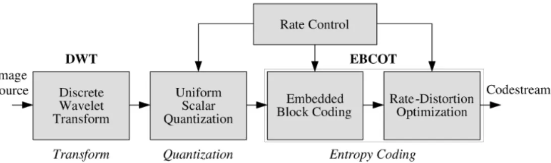
HE JPEG 2000 [1], [2] is well known for its excellent coding performance and numerous features [3], such as scalability, region of interest, error resilience, etc. All these pow-erful tools are provided in a single JPEG 2000 codestream by a unified algorithm. One of the numerous features in JPEG 2000 is scalability, such as spatial and signal to noise ratio (SNR) scala-bility. For example, an image can be losslessly coded for storage and then retrieved at different bit rate to get different spatial size or SNR by transcoding. Transcoding of JPEG 2000 is achieved by parsing, reordering, and truncating the original codestream. The coding performance of JPEG 2000 is superior to JPEG [4] at all bit rate [3].The functional block diagram of JPEG 2000 is shown in Fig. 1. The discrete wavelet transform (DWT) is adopted as the transform algorithm in JPEG 2000. After the DWT, a uniform Manuscript received June 5, 2005; revised March 14, 2006. This work was supported in part by the National Science Council of Taiwan, R.O.C., under Grant 95-2752-E-002-008-PAE, and in part by the MediaTek Fellowship. The associate editor coordinating the review of this manuscript and approving it for publication was Dr. Amid Said.
Y.-W. Chang, C.-C. Cheng, C.-C. Chen, and L.-G. Chen are with DSP/IC Design Lab, Graduate Institute of Electronics Engineering and Department of Electrical Engineering, National Taiwan University, Taipei 10617, Taiwan, R.O.C. (e-mail: [email protected]; [email protected]; [email protected]; [email protected]).
H.-C. Fang was with the Department of Electrical Engineering, National Taiwan University, Taipei 10617, Taiwan. He is now with the MediaTek, Inc., Hsinchu 300, Taiwan, R.O.C (e-mail: [email protected]).
Digital Object Identifier 10.1109/TIP.2006.882013
scalar quantization is applied to transformed coefficients. The entropy coding in JPEG 2000 is the embedded block coding with optimized truncation (EBCOT) [5], [6]. The EBCOT is a two-tiered algorithm. The EBCOT tier-1 is the embedded block coding (EBC), which contains a context formation (CF) and an arithmetic encoder (AE). The CF generates context-decision pairs for the AE to generate embedded bit streams. The AE encodes the binary decision with the probability adapted by the context. The EBCOT tier-2 is called the postcompression rate-distortion optimization (PCRDO), which truncates the embedded bit streams at a target bit rate to provide the optimal image quality. The EBC is the most complex part of JPEG 2000, which consumes more than 50% of total computations [7], [8]. Reducing its computation time can significantly de-crease the total run time of JPEG 2000 encoder.
Most lossy still-image coding standards, including JPEG, use quantization to achieve rate control. However, this method could not optimize image quality. Instead of using quantization method to control the bit rate, JPEG 2000 uses a method to control the bit rate by the PCRDO processing, which is used in the reference software [1]. It uses Lagrange optimization to control the rate precisely while maximizing image quality. However, there are two fatal drawbacks of the PCRDO scheme. First, the computational power of the EBC, which is measured with the number of contexts to be processed, is wasted since the source image must be losslessly coded regardless of the target bit rate. Second, the memory requirement, which is measured with the amount required to buffer the bit streams until the truncations are determined, is large since all the bit streams, including those that are discarded finally, must be buffered until the truncation points are determined by the PCRDO. To alleviate this problem, some previous works [9]–[13] focus on the computational power and the memory requirement reduc-tion for the PCRDO. Masukaki et al. [9] proposed a predictive algorithm. However, the PSNR degradation is more than 1 dB, which may not be acceptable. In [10], the authors use EBCOT tier-2 feedback control to terminate redundant computation of the EBC, and, therefore, the computational power is reduced. Computational power of the EBC is reduced to 40% and 20% at medium and low bit rate, respectively, compared with PCRDO [1]. In [11] and [12], the authors proposed a scheme based on priority scanning. This scheme encodes the coding passes in a different order from high to low priority, and terminates the block coding according to the feedback information from the PCRDO. The computational power and memory requirement are reduced by 52% and 71%, respectively, at 0.25 bits per pixel (bpp). Although the computational power and memory requirement are reduced effectively by previous works, they 1057-7149/$20.00 © 2006 IEEE
3280 IEEE TRANSACTIONS ON IMAGE PROCESSING, VOL. 15, NO. 11, NOVEMBER 2006
Fig. 1. Functional block diagram of JPEG 2000 encoder. The DWT and the EBCOT are adopted as transform and entropy coding algorithm, respectively. EBCOT is a two-tiered algorithm, which contains the EBC and the PCRDO.
introduce some adverse effects. In [10], the feedback control increases control complexity, whereas in [11] and [12], the irregular data access for the EBC is inefficient since all code blocks are randomly accessed. Therefore, additional memory is required to buffer intermediate data. Wu et al. [14] proposed a two-level, hybrid-optimization rate-allocation algorithm for JPEG 2000 transmission over noisy channels. The target is to minimize the expected end-to-end image distortion. Another rate control algorithm [15] is proposed for the motion JPEG 2000. The authors use early termination techniques to skip the unnecessary computations. In [16], the authors proposed a simplified model of delta-distortion to reduce the complexity of the distortion model. The method does not target on the computation reduction of the EBC and, therefore, will not be compared with other methods.
In this paper, a new precompression quality-control (PCQC) algorithm is proposed to solved the above problems. The pro-posed algorithm minimizes bit rate at a given image quality. By estimating rate and distortion before coding, the truncation points are selected before coding. The image quality of the pro-posed algorithm degrades about 0.1 0.3 dB on average com-pared with the PCRDO algorithm. The computational power and memory requirement are also significantly reduced by trun-cating coefficients before the EBC. To maintain low computa-tion overhead, the PCQC algorithm is a low-complexity algo-rithm. It is also designed for simple integration such that neither the EBC nor the coding flow should be modified.
Quality control has an important advantage over the rate con-trol in JPEG 2000. The rate concon-trol in JPEG 2000 suffers from the image-tile dilemma [3] when an image is divided into tiles. When the rate control performs global optimization for the en-tire image, it requires a huge memory to store the bit streams for the whole image. Moreover, the encoding delay is long since the final codestream is generated after the last tile is coded. To solve this problem, tile-based rate control is used, in which the rate is equally distributed to each tile. However, the quality of tile may vary a lot since not all tiles have the same complexity. Thus, the quality of complex tiles are much poorer than that of simple ones. The above dilemma is called image-tile dilemma. For the quality control, this will not happen. The quality-control algo-rithm makes all the tiles have equal quality which is the same as target image quality. Therefore, the quality control can operate on a tile-based manner.
The rest of this paper is organized as follows. Section II gives some background information about JPEG 2000 and
rate-dis-tortion optimization. Several techniques are proposed in Sec-tion III to estimate rate and distorSec-tion before coding. SecSec-tion IV describes the PCQC algorithm in detail. Experimental results are shown in Section V. Finally, the conclusion is drawn in Sec-tion VI.
II. PRELIMINARY
In this section, we will give some background information for the rest of this paper. The coding hierarchy of JPEG 2000 is explained in Section II-A. The rate distortion optimization (RDO) algorithm in JPEG 2000 is described in Section II-B, and the concepts of the PCQC algorithm and the PCRDO algorithm are compared in Section II-C.
A. JPEG 2000 Coding Hierarchy
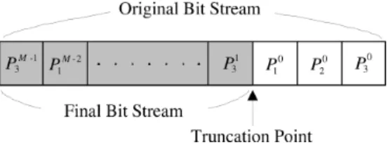
In JPEG 2000, an image is decomposed into various abstract levels for coding, as shown in Fig. 2. At first, an image is parti-tioned into tiles, which are independently coded. Each tile is de-composed by the DWT into subbands with certain decomposi-tion levels. For example, seven subbands are generated with two decomposition levels. Each subband is further partitioned into code blocks, and each code block is independently encoded by the EBC. The DWT coefficients in a code block are sign-mag-nitude represented, and encoded from the most significant bit (MSB) bit plane to the least significant bit (LSB) bit plane. Each bit plane is encoded with three coding passes [2], including the significant propagation pass (Pass 1), the magnitude refinement pass (Pass 2), and the cleanup pass (Pass 3), to generate three embedded bit streams. Within a bit plane, each sample bit is en-coded by one of three coding passes. For each sample in a coef-ficient, a sample bit is denoted as significant one if it is the first nonzero encoded sample bit, or there is a nonzero sample bit has been encoded in previous bit planes. To allow lossy coding, each coding pass is a candidate of truncation point. As shown in Fig. 3, the embedded bit steams of a code block are
orga-nized in the order and where is
the number of nonzero magnitude bit planes of the code block. The embedded bit streams of the code block after the truncation point, say , are discarded to form the final bit stream.
To determine truncation point, the rate and distortion (R-D) of each coding pass are calculated during processing of the EBC. Then, according to the R-D information, the PCRDO deter-mines truncation points for all code blocks to maximize image quality at a target bit rate.
Fig. 2. Decomposition of an image into various abstract levels in JPEG 2000. An image is divided into tiles, subbands, code blocks, bit planes, and three coding passes.
Fig. 3. Organization of embedded bit streams of a code block. They are orga-nized from the MSB bit plane to the LSB bit plane, and Pass 1, Pass 2, and Pass 3 within a bit plane. The whole bit streams are truncated at some truncation point to form the final bit streams.
B. Rate-Distortion Optimization in JPEG 2000
In this section, the RDO algorithm in JPEG 2000 is reviewed. As mentioned in Section II-A, each coding pass is a candidate of truncation point of a code block. For convenience, we define a consecutive integer set to represent all candidates. The candidate corresponding to Pass of the bit plane in the code block ,
, is represented as
(1) In the following discussion, is used to represent for simplicity. Truncating at results in the rate and the distortion . The total bit rates, , and the total distortion, , of the image are
(2) and
(3) The set of selected truncation points for all is denoted as , i.e., . The goal of the RDO is to find the optimal , , to minimize distortion (rate) at target rate (distortion). The optimization algorithms for rate control and quality control are explained in follows.
1) Rate Control: The goal of rate control is to minimize the distortion while keeping the rate smaller than the target rate, . The problem is mapped into Lagrange optimization problem [5] as
(4)
where is the Lagrange multiplier. To minimize ,
the derivative of
(5) is set to zero. Thus, the optimal , , is obtained as
(6) where is the slope of the R-D curve. Since the R-D curve is piece-wise linear, the slope corresponding to in ,
, is obtained by
(7) The physical meaning of is how fast the distortion is re-duced with the increase of the rate when is truncated at . With decrease of the value of , must be strictly decreasing. If some violate this property, the method about merging slopes [5] is used to guarantee the monotonic-decreasing prop-erty. In [5], it has been proved that and are optimal if both (8) and
(9) are satisfied, where is the optimal truncation point for , i.e., . For convenience, the rate control problem is expressed by $ . There is an interesting property
that only and are required to solve$
instead of and . That is to say the optimization is achieved when available is sufficiently close to and the corresponding is also close to , even if the R-D information of the unavailable is unknown.
2) Quality Control: The RDO is achieved by quality control. In order to synchronize with the terminology of RDO algorithm, we use distortion instead of quality. For quality control, the total rate is minimized at the target distortion, . The optimization can also be achieved by Lagrange equation
3282 IEEE TRANSACTIONS ON IMAGE PROCESSING, VOL. 15, NO. 11, NOVEMBER 2006
Fig. 4. Comparison between the PCRDO and the PCQC schemes. (a) PCRDO determines truncation points after the EBC. (b) PCQC determines truncation points before the EBC.
where is the Lagrange multiplier for distortion control, which is interpreted as a quality parameter [2]. For convenience, this optimization problem is expressed as$ . To mini-mize
(11) is used to find as
(12) The is optimal if the distortion cannot be reduced without the increase of the rate, or, equivalently, the rate cannot be reduced without the increase of the distortion. Therefore, it is intuitive
that the for$ is the same as the for$
.
C. PCRDO and PCQC Comparisons
The PCRDO is illustrated in Fig. 4(a). In this scheme, the original DWT coefficients are losslessly compressed by the EBC. The whole bit streams as well as R-D information are all buffered in memory. For image-based PCRDO, all the data of the entire image must be buffered. On the other hand, data for only one tile are buffered in tile-based PCRDO. The PCRDO selects the optimal set of truncations points to form the final bit stream according to the R-D information. The bit streams after the truncation points discarded. Therefore, the computational power for the discarded bit streams is wasted.
Fig. 4(b) illustrates the PCQC. The truncation points are se-lected before actual coding, and then the truncated coefficients are coded by the EBC. All the embedded bit streams of the re-maining coding passes result in the final bit stream. Therefore, the computational power is reduced because that unnecessary processing for the EBC is skipped. Moreover, the memory re-quirement are reduced since the EBC do not generate bit streams
for the truncated parts of the DWT coefficients. The PCQC op-erates on a tile-based manner that each tile is coded by the same quality as the target image quality.
III. R-D CALCULATIONBEFORECOMPRESSION To perform rate-distortion optimization, the incremental
dis-tortion and the incremental rate are required
as described in previous section. However, there are two prob-lems in determining the truncation points before coding. First, the coding pass of a sample bit is unknown before actual coding. Second, the rate of each coding pass is unavailable before com-pression. In this section, we propose several techniques to
esti-mate and in the DWT domain by utilizing
propa-gation property and randomness property of the EBC. A. Image Quality Control
To control image quality, the distortion in the pixel domain is required. In this section, we will show how to estimate the distortion in the pixel domain by the distortion in the DWT do-main.
If the truncation errors for the DWT coefficients are uncorre-lated, i.e., zero mean white noise, it has been found [5] that the average distortion per pixel, , is estimated by a weighted sum of the average distortion of every subband in the DWT domain as
(13) where is the average distortion of the subband
de-noted by , is the image size, and is the
corre-sponding weighting factor. The represents any subband,
i.e., ,
where is the decomposition level. By applying the analytic method mentioned in [17], is derived and the results are listed in Table I.
TABLE I
DISTORTIONWEIGHTINGFACTORS FOR5-3AND9-7 FILTER
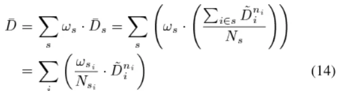
As mentioned in Section II-A, a subband is divided into sev-eral code blocks. Therefore, is expressed as
(14) where is the distortion of truncated at in the DWT domain. The and are the corresponding weighting factor and size of the subband that the belongs to.
B. Rate Estimation
To obtain the slope, , must be estimated since
is unknown before actual coding by the EBC. The accuracy of estimation is essential to perform RDO without significant quality loss. Two properties, randomness and propa-gation, of the EBC algorithm are used to increase the accuracy of the estimation.
Randomness represents the random property of Pass 2. It means that the appearance of 0 and 1 for a sample bit belonging to Pass 2 is random and, therefore, results in constant coding gain of Pass 2. The coding gain of Pass 2 is almost constant regardless of images, decomposition levels, subbands, code blocks, and bit planes. Fig. 5(a) shows the randomness property of Pass 2. The horizontal axis shows the number of sample bits that belong to the coding pass, and the vertical axis is the length of resulting embedded bit stream in bits. Each point in Fig. 5 represents one embedded bit stream of Pass 2 in different images, decomposition levels, subbands, code blocks, and bit planes. As can be seen, the coding gain is almost constant, which is close to one. Therefore, the rate of Pass 2 is accurately estimated by the bit counts.
Unlike Pass 2, the coding gain of Pass 1 varies from bit plane to bit plane and from image to image. However, the rate of Pass 1 in the lowest two bit planes are approximately proportional to the bit counts of sample bits belonging to Pass 1 since the samples bits have noise-like distribution. Fig. 5(b) shows the randomness property of Pass 1 in the lowest two bit planes. Although it is not as random as Pass2, it is random enough to achieve small estimation errors. The coding gain is denoted as , and the experimental results show that . This indicates the inefficiency for coding Pass 1 in the lowest two bit
planes because of the prediction error caused by the noise-like distribution for sample bits.
Another property, propagation, is also utilized to increase the number of candidates of truncation points. This property means that most of the insignificant samples in the lowest two bit planes are propagated as Pass 1 by the neighboring significant samples. Fig. 6 shows the distribution of three coding passes from the LSB bit plane, which is called bit plane 0 hereafter, to the MSB bit plane for the 5-3 filter. Experimental result shows that about 5% insignificant samples belong to Pass 3 in the lowest two bit planes [7]. Thus, we assume that a sample bit in the lowest two bit planes is very likely to belong to Pass 1 if it does not belong to Pass 2 since Pass 3 is negligible. Therefore, we classify the samples that do not belong to Pass 2 into Pass 1 in the lowest two bit planes.
Combining the above analysis, of Pass 1 in the lowest two bit planes and Pass 2 in all bit planes is estimated by bit counts. To compute bit counts, the Pass 2 detection for each sample bit is required. Let denotes the value of the th DWT coefficient in a code block, and denote the value of the sample bit at bit plane of . An indicator of whether belongs to Pass 2 or not, , is defined as
(15) With , the bit counts, , in the bit plane is computed by
(16)
where is complement operator and is that the trun-cation point, , is Pass 1 in the th bit plane. Then, is obtained by
(17)
C. Distortion Estimation
In this section, we will show how to calculate . It is precisely estimated since it only depends on the value of coeffi-cient.
3284 IEEE TRANSACTIONS ON IMAGE PROCESSING, VOL. 15, NO. 11, NOVEMBER 2006
Fig. 5. Randomness property of Pass 2 and Pass 1. (a) Compression ratios of Pass 2 in different images, subbands, code blocks and bit planes are almost the same. (b) Compression ratios of Pass 1 in lowest two bit planes are near constant.
For convenience, we define two terms
(18) and
(19) where is bit wise and the operator. The is the value of
under the bit plane . The incremental distortion for truncated at , , is calculated by
Fig. 6. Percentage for distribution of three coding passes for 5-3 filter from bit plane 0 to MSB bit plane in the second decomposition level (except LL band).
where is the reconstructed value of if is selected as final truncation point for . Thus, the incremental distortion in the DWT domain for , , is accumulated by
(21) Then, the incremental distortion in the pixel domain, , is obtained by
(22) With the defined terms, is estimated by
(23)
where is the truncation error of truncated at . It is computed by
(24) Note that is overestimated since we assume all insignificant samples at the bit plane are truncated. Image distortion, , is
(25)
which is obtained by substituting (23) into (13).
IV. PRECOMPRESSIONQUALITY-CONTROLALGORITHM
From the above discussions, and are estimated
before coding. In this section, we propose a PCQC algorithm
that determines truncation points before coding by the estimated
and .
Fig. 7(a) shows the position of the PCQC algorithm in JPEG 2000 encoding system. It processes DWT coefficients in a tile to determine truncation points, and then the truncated coefficients are encoded by the EBC. Integrating PCQC in a JPEG 2000 system does not change the coding flow. Moreover, no modifi-cation is required for the EBC. It operates as if there is no PCQC inserted. In the PCQC, the distortion constraint of the image, , is evenly distributed into each tile, and, thus, the quality of each tile is similar. Therefore, the proposed algorithm is a tile-based algorithm, i.e., the distortion control is independent for each tile.
The flowchart of the PCQC algorithm is shown in Fig. 7(b). It comprises two processing stages. The first stage, shown in the left part, is a nested looping process to calculate and accumulate the R-D information of all code blocks in the tile. The second stage, shown in the right half part of the figure, is to determine truncation points for all code blocks according to the normalized R-D information. The detailed operations of each function in Fig. 7(b) are described as follows.
A. Distortion Calculation
This function calculates the distortion in the DWT domain. It calculates the truncation error by (24), and then accumulates
to obtain by (23). B. Incremental R-D Calculation
The incremental distortion, , contributed by current bit is calculated by (20). Then, it is added to the corresponding by (21). On the other hand, the bit count for each is also accumulated by (16) to obtain .
C. R-D Normalization
After the first stage, , , and for all blocks
3286 IEEE TRANSACTIONS ON IMAGE PROCESSING, VOL. 15, NO. 11, NOVEMBER 2006
Fig. 7. (a) Position of the PCQC algorithm in JPEG 2000 encoding system. The PCQC scans coefficients in a tile and decides the truncation points for all the code blocks in the tile. (b) Flowchart of the PCQC algorithm. All code blocks in a tile are processed to obtain R-D information. The optimal truncation points are decided to meet the distortion constraint according the normalized R-D information.
Fig. 8. Concept of slope interpolation for 9-7 filter. In the lowest two bit planes, the slopes of Pass 1 and Pass 3, the hollow points, are interpolated by the slope of Pass 2, the solid points. The dashed lines are missing truncation points of the PCQC algorithm.
generate , , and by (22), (25), and (17), respec-tively. Then, can also be obtained by (7).
D. Candidates Increase
As described in Section III-B, the propagation property is used to truncate at Pass 1 in the lowest two bit planes. This property comes from the fact that most insignificant sample bits belonging to Pass 1 due to the propagation of significant coeffi-cients. However, this assumption may fail if all the DWT coef-ficients are very small. This occurs frequently for 9-7 filter due to its good energy compaction capability. Experimental results show that 7% and 30% sample bits belong to Pass 3 in bit plane 0 and bit plane 1, respectively. Thus, truncating these bits-planes
TABLE II
CANDIDATES OFTRUNCATIONPOINT
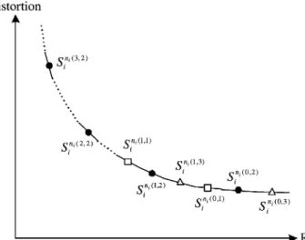
at Pass 1 introduces large errors. Therefore, only Pass 2 is pos-sible truncation point for 9-7 filter. To increase the number of candidates of truncation points, the interpolation technique is used to estimate the slopes of Pass 1 and Pass 3 in the lowest two bit planes.
Assume that the shape of the R-D curve of a code block is convex, as shown in Fig. 8. Moreover, the R-D curve is piecewise linear since the coding passes are discrete. In Fig. 8, the dashed lines represent the missing truncation points of the PCQC algorithm. The slopes of Pass 1 and Pass 3 in the lowest two bit planes, the hollow points, are estimated by
(26)
where , , , and are interpolation parameters. These parameters are experimentally determined by averaging the pa-rameters obtained from simulating various test images. For the bit planes higher than two, the interpolation technique is not
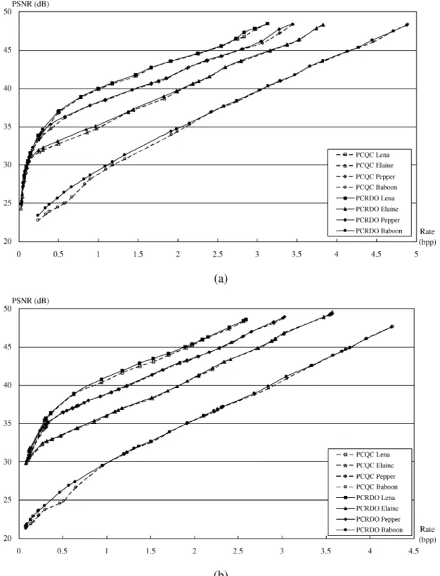
Fig. 9. Objective comparisons between the proposed PCQC algorithm and the PCRDO algorithm. (a) R-D curves for 5-3 filter with two decomposition levels. (b) R-D curves for 9-7 filter with five decomposition levels.
used since the numbers of samples bits belonging to Pass 2 are too few to be represented. Finally, the candidates of truncation points in the proposed algorithm are summarized in Table II. E. Truncation Point Decision
With the obtained slopes in Table II, the truncation points are decided to meet the distortion constraint for the tile. In [6], a procedure is proposed to select optimal truncation points by the slopes for rate control. Since this procedure can also be applied
to the distortion control, we adopt the same procedure in the pro-posed algorithm. According to the truncation points, the DWT coefficients are truncated before the EBC.
V. EXPERIMENTALRESULTS
A. Coding Performance
In this section, we compare the coding performance of the proposed algorithm with the PCRDO algorithm [1]. Fig. 9 show
3288 IEEE TRANSACTIONS ON IMAGE PROCESSING, VOL. 15, NO. 11, NOVEMBER 2006
TABLE III
CODINGPERFORMANCECOMPARISON OFLena
the comparisons of 5-3 and 9-7 filters, respectively. The four test images are gray level with size 512 512. The tile size is 512 512, and the code block size is 64 64. For 9-7 filter, the interpolation parameters, , , , and are all 1/3. This value is experimentally determined by averaging the pa-rameters obtained from simulating various test images. The de-tailed results for Lena with five decomposition levels are listed in Table III, in which CR means compression ratio. Compared with the PCRDO algorithm, there is almost no quality degra-dation for PSNR higher than 35 dB. For the PSNR lower than 35 dB, the quality degradation is about 0.2 0.7 dB. In the worst case, the quality may degrade 1 dB at very low bit rates. How-ever, it may not be suitable to perform quality control at very low bit rate since rate is concerned more than quality. For some applications such as low bit rate transmission and wireless re-mote sensing, precise rate control is a critical issue due to lim-ited bandwidth.
There are four reasons for the quality degradation. First, the rate is estimated, and the estimation error would result in inac-curate slope. Second, at lowest two bit planes, the propagation property is not always held even for the 5-3 filter. Classifying all insignificant samples into Pass 1 would overestimate both the rate and distortion of Pass 1. Third, the number of candidates of truncation point at the bit plane higher than two are insufficient. Thus, the quality would be degraded if the available truncation points are far from the optimal truncation points. Finally, slope of Pass 2 is not the representative in the bit plane higher than two since only a few sample bits belong to Pass 2. This may be the reason that the quality degradation is larger at very low bit rate than other regions.
B. Comparisons
In this section, we will show the effectiveness of the pro-posed algorithm to reduce computational power and memory requirement by comparing our method with previous works.
Fig. 10 shows comparisons of the normalized computational power with Chang’s algorithm [10]. The computational power is measured by the percentage of number of contexts to be pro-cessed by the EBC since it is proportional to the computational complexity [7]. The 100% in the Fig. 10 represents the com-putational power of [1] since all contexts are losslessly pro-cessed. For simplicity, the [1] is omitted in the Fig. 10. As can be seen from Fig. 10, the proposed algorithm has better com-putational power reduction than [10] at all bit rates for all test images. Note that the computational power is also proportional to the processing time. Thus, the processing time of the EBC of the proposed algorithm is also shorter than that of [10]. The detailed results for Lena of the proposed algorithm in Fig. 10 are shown in Table IV. The memory in the Table IV means the memory requirement for buffering the generated bit streams from the EBC. It does not contain the memory requirement for R-D information. Note that, if an image is losslessly coded, the reduction ratio is zero since all the generated bit streams should be buffered. The detailed composition of the memory require-ment will be described in the following section. The results of the computational power in other previous works [9], [13] are presented by averaging results for various images. This some-what makes it hard to have a fair comparison since the charac-teristics of various images are quite different. Nevertheless, our experimental results are also averaged to be compared with the others. In the following comparisons, our curves are the average results of 5 standard images including Lena, Baboon, Pepper, Jet, and Elaine. All the images are gray-level 512 512 pixels compressed by 9-7 filter with 5 decomposition levels without dividing into tiles and the code block size is 64 64. Fig. 11 shows the average percentage of computational power to be pro-cessed by the EBC for various algorithms. The reduction rate of the proposed algorithm is similar to successive bit-plane rate allocation (SBRA) algorithm [13] and priority scanning rate al-location (PSRA) algorithm [13], and is much better that others. The computational power reduction result in [9] is measured by the number of coding passes. It is not compared here since the number of coding passes to be coded is not proportional to com-putational power. Some coding passes may have many contexts while others may not. Thus, the ratio of the number of processed coding passes against total number of coding passes does not di-rectly reflect on the computational power.
Another important factor is the memory required for the algorithm. The memory requirement contains two parts, the memory for buffering bit streams generated from the EBC and the memory for buffering R-D data. It is hard to compare the memory requirement for buffering the R-D data since it depends on precision used for rate and distortion. However, this requirement is quite small since only several bits are required for a coding pass. In the proposed algorithm, each coding pass requires 28 bits, in which 12 bits for rate and 16 bits for distor-tion. For the memory requirement for buffering bit streams, it can be further divided into two sub-parts. The first part is the memory for buffering the bit streams that are included into the final bit streams after the truncation points are determined, and the second part is the memory for buffering the bit streams that are discarded finally. For the first part, it cannot be reduced no matter which R-D optimization algorithm is used since the
Fig. 10. Comparisons of the power reduction between the proposed PCQC algorithm and the previous work [10]. (a) Normalized computational power for 5-3 filter. (b) Normalized computational power for 9-7 filter.
final bit streams should be buffered for the header generation. For the second part, it is the additional buffer for the issue of finding optimal truncation points. This requirement depends on which R-D algorithm is used. In the proposed algorithm, the memory requirement for the second part is zero since the truncation points are determined before coding. All the gen-erated bit streams from the EBC are the final bit streams. For
the SBRA in [13], the memory requirement for the second part is also zero since it is a predictive and incremental algorithm. The next coding pass is determined by prediction after the previous coding pass is finished. The coding process of the EBC is terminated until the target bit rate is reached and all the generated bit streams result into the final bit streams. For the PSRA in [13], the memory requirement for the second part is
3290 IEEE TRANSACTIONS ON IMAGE PROCESSING, VOL. 15, NO. 11, NOVEMBER 2006
Fig. 11. Comparisons of the power reduction between the proposed PCQC algorithm and the previous work [13].
TABLE IV
COMPUTATIONALPOWER ANDMEMORYREDUCTION OF THEPCQC FROMPCRDOFORLena
about one coding pass. This memory is used to buffer the bit stream of the newest coding pass. After the memory for the first part is full, the PSRA discards one coding pass with the lowest slope in this memory, and the newest coding pass becomes one part of this memory if the slope of the newest coding pass is larger than that of the discarded one. The priority scanning with optimal truncation (PSOT) in [13] is the extended algorithm of the PSRA, it can find the optimal truncation points at a cost of more additional buffer. The memory requirement for the
second part is 80% or 200% of that for the first part at a target bit rate 1.0 or 0.25 bpp (CR 8 and 32), respectively.
In previous two paragraphs, we compared the computation and memory reductions of various algorithms. It is important to check whether there is significant quality degradation due to the reduction or not. Fig. 12 shows the average PSNR degrada-tion (PSNR-D), measured by PSNR of various algorithms minus that of PCRDO algorithm [1]. The PSNR-D of the proposed algorithm becomes large near 0.27 bpp due to the estimation error and insufficient truncation points. Actually, the proposed algorithm is not suitable for such low bit rate. It is suggested to use the proposed algorithm at quality higher than 30 dB. The PSNR-D of the proposed algorithm is slightly larger than that of the PSRA and the PSOT in [13] but our algorithm has better both computational power and memory requirement reduction than that of the PSOT and has better memory requirement re-duction than that of the PSRA.
Finally, we compare various algorithms in an aspect of inte-gration with JPEG 2000. For [9], [10], and [13], all the algorithms are based on PCRDO to reduce the computational power and the memory requirement. For [9], [10], and [13], these algorithms are operated in parallel with the EBC in an order of a code block by a code block. Therefore, all of them need feedback control to the EBC to control the encoding data flow and terminate en-coding process at a proper time. The feedback control increases the difficulties to integrate these algorithms into JPEG 2000. For PSRA and PSOT in [13], they require a big change in coding flow since the bit planes of each code block in a tile are ran-domly accessed. They are incremental algorithms, i.e., the next coding pass is determined after finish of the previous encoding pass. The incremental and random properties introduce compli-cated control and irregular data flow. For the proposed algorithm,
Fig. 12. Comparisons of average PSNR Difference (PSNR-D) between various algorithms with the PCRDO algorithm. Although the PCQC algorithm degrades sharply near 0.2 bpp, it does not matter since the proposed algorithm does not apply in this rate range in normal cases.
Fig. 13. Controllability of the proposed algorithm. The horizontal axis is the target PSNR, and the vertical axis is the resulting PSNR.
it does not require the change of coding flow and the modification of the DWT or the EBC. All the coefficients of each code block in a tile are scanned once, as shown in Fig. 7(a) and Fig. 7(b), and the truncation points are determined before the coding of the EBC. The proposed algorithm can be easily integrated into any system, either software or hardware [18].
The proposed algorithm is orthogonal to any existing R-D optimized algorithms based on PCRDO. The quality control can
be used before coding to skip most of computational power and to reduce memory requirement for the EBC, and then the rate control follows to control the bit rate after coding. By use of joint control for quality and rate, there would be no quality loss at low bit rate since the rate control achieves RDO with precise R-D information. The overhead of rate control becomes small since the proposed algorithm skips most of the computations of the EBC.
3292 IEEE TRANSACTIONS ON IMAGE PROCESSING, VOL. 15, NO. 11, NOVEMBER 2006
C. Distortion Control Precision
This section shows the precision of the distortion control. The precision means how close it is between the target distortion and the resulting distortion. Fig. 13 shows the results. The horizontal axis is the target quality and the vertical axis is the resulting quality. The solid line is the ideal case. At the range of 25 to 45 dB, the difference is smaller than 1.5 dB, which is almost in-distinguishable by human eyes. Although the difference seems large for PSNR higher than 45 dB, the corresponding compres-sion ratio is usually lower than 4, and is an unusual operation range for image compression. Moreover, human also cannot ob-serve the difference at such high quality.
The estimation errors of distortion come from two reasons. First, the used distortion model defined in (25) is under the as-sumption that the truncation errors are uncorrelated white noise. However, this assumption is not always held for natural images, especially at near lossless region. Therefore, there would be esti-mation errors. Second, we assume that insignificant coefficients are all truncated regardless of , which is described in (23), and it overestimates the distortion.
VI. CONCLUSION
A PCQC algorithm, which minimizes rate with a given quality, is presented in this paper. The proposed algorithm significantly reduces the computational power of the entropy coder and memory requirement to buffer embedded bit streams. It is achieved by utilizing randomness property and propagation property. By utilizing these two properties, the truncation points are chosen before actual coding of the EBC. Therefore, the computational power and memory requirement are reduced. As shown by the extensive experiments, the coding performance is almost the same as the PCRDO for bit rate higher than 0.27 bpp. Compared with PCRDO, the computational power and the memory requirement are reduced to 20% and 10% on average at 0.8 bpp, respectively. The proposed algorithm can be easily adopted into any JPEG 2000 system, either software or hardware, since it does not modify the coding flow of the EBC.
REFERENCES
[1] JPEG 2000 Verification Model 7.0 (Technical Description), ISO/IEC JTC1/SC29/WG1 N1684, Apr. 2000.
[2] JPEG 2000 Part I: Final Draft International Standard (ISO/IEC
FDIS15444-1), ISO/IEC JTC1/SC29/WG1 N1855, Aug. 2000.
[3] A. Skodras, C. Christopoulos, and T. Ebrahimi, “The JPEG 2000 still image compression standard,” IEEE Signal Process. Mag., vol. 18, no. 5, pp. 36–58, Sep. 2001.
[4] W. Pennebaker and J. Mitchell, JPEG: Still Image Data Compression
Standard. New York: Van Nostrand Reinhold, 1992.
[5] D. Taubman, “High performance scalable image compression with EBCOT,” IEEE Trans. Image Process., vol. 9, no. 7, pp. 1158–1170, Jul. 2000.
[6] D. Taubman, E. Ordentlich, M. Weinberger, and G. Serourssi, Em-bedded Block Coding in JPEG 2000, vol. 2. Vancouver, BC, Canada, Sep. 2000, pp. 33–36.
[7] C.-J. Lian, K.-F. Chen, H.-H. Chen, and L.-G. Chen, “Analysis and architecture design of block-coding engine for EBCOT in JPEG 2000,”
IEEE Trans. Circuits Syst. Video Technol., vol. 13, no. 3, pp. 219–230,
Mar. 2003.
[8] M.-D. Adams and F. Kossentini, JasPer: A Software-Based JPEG-2000 Codec Implementation, vol. 2. Vancouver, BC, Canada, Sep. 2000, pp. 53–56.
[9] T. Masuzaki, H. TsuTsui, T. Izumi, T. Onoye, and Y. Nakamura, “JPEG2000 adaptive rate control for embedded systems,” in Proc.
IEEE Int. Symp. Circuits. Syst., Scottsdale, AZ, May 2002, vol. 4, pp.
333–336.
[10] T.-H. Chang, L.-L. Chen, C.-J. Lian, H.-H. Chen, and L.-G. Chen, Computation Reduction Technique for Lossy JPEG2000 Encoding Through Ebcot Tier-2 Feedback Processing vol. 3. Rochester, NY, Jun. 2002, pp. 85–88.
[11] Y.-M. Yeung, O. C. Au, and A. Chang, Efficient Rate Control Tech-nique for JPEG2000 Image Coding Using Priority Scanning, vol. 3. Baltimore, MD, Jul. 2003, pp. 277–280.
[12] ——, An Efficient Optimal Rate Control Scheme for JPEG2000 Image Coding, vol. 2. Barcelona, Spain, Sep. 2003, pp. 761–764. [13] Y. M. Yeung and O. C. Au, “Efficient rate control for JPEG2000 image
coding,” IEEE Trans. Circuits Syst. Video Technol., vol. 15, no. 3, pp. 335–344, Mar. 2005.
[14] Z. Wu, A. Bilgin, and M. W. Marcellin, “An efficient joint source-channel rate allocation scheme for JPEG2000 codestreams,” in Proc.
IEEE Data Compression Conf., Mar. 2003, pp. 113–122.
[15] W. Chan and A. Becker, “Efficient rate control for motion JPEG2000,” in Proc. IEEE Data Compression Conf., Mar. 2004, pp. 529–529. [16] X. Qin, X.-L. Yan, X. Zhao, C. Yang, and Y. Yang, “A simplified model
of delta-distortion for JPEG2000 rate control,” in Proc. IEEE
Interna-tional Conf. Communications, Circuits, and Systems, Jun. 2004, pp.
548–552.
[17] J. W. Woods and T. Naveen, “A filter based bit allocation scheme for subband compression of HDTV,” IEEE Trans. Image Process., vol. 1, no. 3, pp. 436–440, Jul. 1992.
[18] H.-C. Fang, C.-T. Huang, Y.-W. Chang, T.-C. Wang, P.-C. Tseng, C.-J. Lian, and L.-G. Chen, “81 MS/s JPEG 2000 single-chip encoder with rate-distortion optimization,” in Proc. IEEE Int. Solid-State Circuits
Conf. Dig. Tech, Papers, San Francisco, CA, Feb. 2004, pp. 328–329.
Yu-Wei Chang was born in Taipei, Taiwan, R.O.C., in 1980. He received the B.S. degree in electrical en-gineering from National Taiwan University, Taipei, in 2003, where he is currently pursuing the Ph.D. degree in the Graduate Institute of Electronics Engineering. His research interests include algorithm and ar-chitecture for image/video signal processing, image coding systems, and video compression systems.
Hung-Chi Fang was born in I-Lan, Taiwan, R.O.C., in 1979. He received the B.S. degree in electrical engineering and the Ph.D. degree from the National Taiwan University, Taipei, in 2001 and 2005, respec-tively.
In 2005, he was a visiting student at Princeton Uni-versity, Princeton, NJ, with Prof. Wolf, supported by the Graduate Students Study Abroad Program of the National Science Council. Currently, he is a Senior Engineering with MediaTek, Inc., Hsinchu, Taiwan.
His research interests are VLSI design and imple-mentation for signal processing systems, image processing systems, and video compression systems.
Chih-Chi Cheng was born in Taipei, Taiwan, R.O.C., in 1982. He received the B.S. degree in electrical engineering from the National Taiwan University, Taipei, in 2004, where he is currently pursuing the Ph.D. degree at the Graduate Institute of Electronics Engineering.
His research interests include algorithms and architectures for image/video signal processing, discrete wavelet transforms (DWT), and intelligent video processing.
Chun-Chia Chen was born in Changhwa, Taiwan, R.O.C., in 1982. He received the B.S. degree in electrical engineering from the National Taiwan University, Taipei, in 2004, where he is currently pursuing the M.S. degree at the Graduate Institute of Electronics Engineering.
His research interests include algorithm and archi-tecture for JPEG 2000 and JBIG2.
Liang-Gee Chen (S’84–M’86–SM’94–F’01) was born in Yun-Lin, Taiwan, R.O.C., in 1956. He received the B.S., M.S., and Ph.D. degrees in elec-trical engineering from the National Cheng Kung University (NCKU), Tainan, Taiwan, in 1979, 1981, and 1986, respectively.
He was an Instructor (1981 to 1986) and an Asso-ciate Professor (1986 to 1988) in the Department of Electrical Engineering, NCKU. During his military service from 1987 to 1988, he was an Associate Pro-fessor with the Institute of Resource Management, Defense Management College. In 1988, he joined the Department of Electrical Engineering, National Taiwan University (NTU), Taipei. From 1993 to 1994, he was a Visiting Consultant with the DSP Research Department, AT&T Bell Labs, Murray Hill, NJ. In 1997, he was a Visiting Scholar with the Department of Electrical Engineering, University of Washington, Seattle. From 2001 to 2004, he was the first director of the Graduate Institute of Electronics Engineering (GIEE), NTU. Currently, he is a Professor with the Department of Electrical Engineering, GIEE, NTU. He is also the director of the Electronics Research and Service Organization in Industrial Technology Research Institute, Hsinchu, Taiwan. His current research interests are DSP architecture design, video pro-cessor design, and video coding systems.
Dr. Chen has served as an Associate Editor of the IEEE TRANSACTIONS ON
CIRCUITS ANDSYSTEMS FORVIDEOTECHNOLOGYsince 1996, an Associate Editor of the IEEE TRANSACTIONS ONVLSI SYSTEMSsince 1999, and an As-sociate Editor of the IEEE TRANSACTIONS ONCIRCUITS ANDSYSTEMS—II: EXPRESSBRIEFSsince 2000. He has been the Associate Editor of the Journal
of Circuits, Systems, and Signal Processing since 1999 and a Guest Editor for
the Journal of Video Signal Processing Systems. He is also the Associate Ed-itor of the PROCEEDINGS OF THEIEEE. He was the General Chairman of the 7th VLSI Design/CAD Symposium in 1995 and the 1999 IEEE Workshop on Signal Processing Systems: Design and Implementation. He is the Past Chair of the Taipei Chapter of IEEE Circuits and Systems (CAS) Society and a member of the IEEE CAS Technical Committee of VLSI Systems and Applications, the Technical Committee of Visual Signal Processing and Communications, and the IEEE Signal Processing Technical Committee of Design and Implementation of SP Systems. He is the Chair-Elect of the IEEE CAS Technical Committee on Multimedia Systems and Applications. From 2001 to 2002, he served as a Dis-tinguished Lecturer of the IEEE CAS Society. He received the Best Paper Award from the R.O.C. Computer Society in 1990 and 1994. Annually, from 1991 to 1999, he received Long-Term (Acer) Paper Awards. In 1992, he received the Best Paper Award of the 1992 Asia-Pacific Conference on circuits and systems in the VLSI design track. In 1993, he received the Annual Paper Award of the Chinese Engineer Society. In 1996 and 2000, he received the Outstanding Re-search Award from the National Science Council, and in 2000, the Dragon Ex-cellence Award from Acer. He is a member of Phi Tan Phi.


![Fig. 10. Comparisons of the power reduction between the proposed PCQC algorithm and the previous work [10]](https://thumb-ap.123doks.com/thumbv2/9libinfo/8855506.243586/11.891.115.769.99.939/fig-comparisons-power-reduction-proposed-pcqc-algorithm-previous.webp)
