• 沒有找到結果。

Energy control by linking individual patterns to self-repeating diffractive optical elements

N/A
N/A
Protected

Academic year: 2021

Share "Energy control by linking individual patterns to self-repeating diffractive optical elements"

Copied!
11
0
0

加載中.... (立即查看全文)

全文

(1)

Energy control by linking individual patterns

to self-repeating diffractive optical elements

C. Y. Lu, H. Z. Liao, C. K. Lee, and J. S. Wang

In general, as diffractive optical elements formed by use of self-repeating patterns possess beneficial characteristics such as scratch resistance, low design effort, ease of fabrication, and natural formation of large panels, an efficient design methodology that was developed with a modified preserving-the-best strategy of genetic algorithms is presented. Both genetic algorithms and simulated annealing are examined by the Markov-chain stochastic process to create the insight needed to use these two heuristic algorithms efficiently. It was found that adding the preserving-the-best strategy to traditional genetic algorithms guarantees the possibility of locating the global optimum. Combining this sufficient and necessary condition for locating a global optimum for genetic algorithms with the built-in chromosome crossover searching mechanism and its neighborhood identification makes this newly developed genetic algorithm an effective method for designing diffractive optical elements. In our study, a prototype was fabricated based on our case study with the modified genetic algorithm. The performance of this prototype was measured and analyzed. Experimental results are shown to agree well with theoretical predictions. © 1997 Optical Society of America

Key words: Diffractive optical elements, binary optics, genetic algorithms.

1. Introduction

Using self-repeating patterns to form large diffractive optical elements ~DOE’s! provides us with a way to create a DOE that is virtually scratch resistant, sim-ilar to that of traditional holograms. More specifi-cally, self-repeating patterns can be used to store information that will not be damaged even when sur-face patterns are partially damaged. Using this con-cept to generate large-format DOE’s has been shown to reduce significantly computational time and other costs involved because of its fundamental character-istics. DOE’s generated by the combination of self-repeating patterns are thus examined in this paper to investigate the possibility of distributing input light beams into user-specified energy patterns; that is, one of our main objectives in this paper is to examine the methodologies of designing DOE’s capable of as-signing prespecified output-energy distribution ratios to any user-defined direction.

Currently there are many computational algo-rithms that exist for designing DOE’s.1–3 However,

the design of complex DOE’s is typically viewed as a search for solutions to minimization problems in mul-tidimensional discrete variable domains. Iterative algorithms,4 – 8 which can be classified into

bidirec-tional iterative algorithms, such as the iterative Fourier-transform algorithms9 –13 ~IFTA!, and the

unidirectional iterative algorithms, such as the heu-ristic algorithms,14 –20are typically used in

approach-ing these types of problems. The main difference between the bidirectional and the unidirectional al-gorithms lies in the requirement of identifying the inverse mapping within the algorithm. More specif-ically, using a bidirectional iterative algorithm re-quires a fundamental understanding of not only the influence that the DOE has on the image produced and on the design metric, but also of how variations in the response affect the DOE.

As only scalar-domain analysis is discussed in this paper, either a Fresnel diffraction or a Fourier dif-fraction is quite applicable in the design of DOE’s examined here. Thus algorithms such as the IFTA can be readily applicable for these types of problems. However, it should be noted that, even though the IFTA is simple to implement, it is prone to stagnate in local minima.1,11,12 Exploitation of design

free-dom to redistribute DOE design values while secur-ing the desired performance objective in the image plane is a necessary condition to adopting the IFTA effectively. On the other hand, a unidirectional al-The authors are with the Institute of Applied Mechanics,

Na-tional Taiwan University, Taipei, Taiwan, China.

Received 4 September 1996; revised manuscript received 19 De-cember 1996.

0003-6935y97y204702-11$10.00y0 © 1997 Optical Society of America

(2)

gorithm characterizes DOE’s by a finite set of quan-tified parameters and then executes a finite but typically large number of permutations of these de-sign parameters. For the case in which the model of the optical systems cannot be easily inverted, a uni-directional algorithm should be the choice. Al-though both types of algorithms can be successfully adopted in designing the DOE’s of this paper, our efforts are concentrated on revealing the fundamen-tal mathematical structures of the most popular uni-directional algorithms, i.e., the genetic algorithm14 –17

~GA! and simulated annealing18 –20 ~SA!, in order to

facilitate the use of these algorithms.

In an attempt to optimize the numerical coding process, a stochastic process is adopted in this paper to examine the fundamental relationship between the GA and SA. Furthermore, the understanding obtained from this paper provides us with an oppor-tunity to adjust the tuning parameters that exist within these algorithms more intelligently. It is also identified that a modified GA with a preserving-the-best strategy has the necessary and sufficient conditions to ensure the convergence of the numerical calculations. Even though SA is not examined in great detail in this paper, the stochastic process we have adopted has been shown to provide us with a way to code these two important heuristic algorithms in an identical manner with some minor modifica-tions.

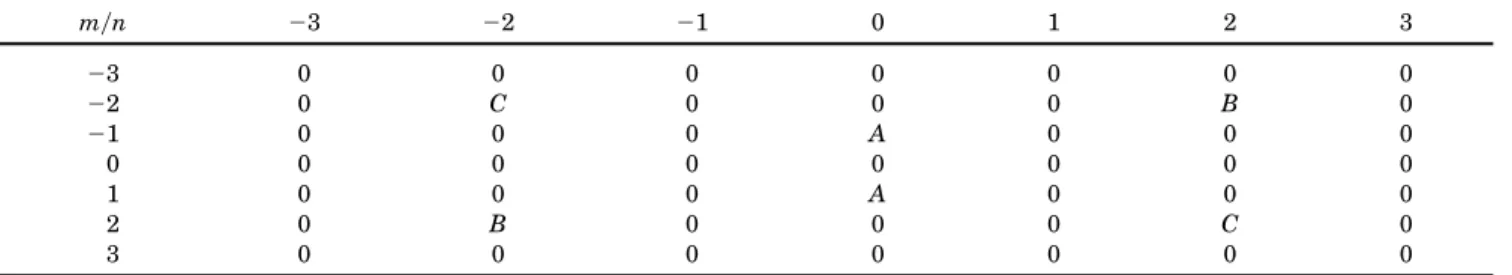
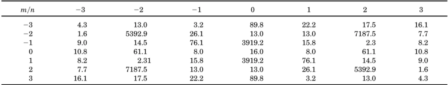
A 163 16 pixel array was designed as a unit cell for the repetition of the large DOE panel in order to redistribute the incident light beam into a desired pattern. As the first three positive and negative or-ders of diffractive light were considered for the output pattern, a total of 73 7 points were specified. With our design approach, the ability to specify arbitrarily the energy ratio within each of these 7 3 7 points produces a significant amount of information that can be stored in such a simple pattern. To examine the sensitivity of our final design, a 643 64 pixel array of a self-repeating unit with respect to a 93 9 output point was also calculated to compare results.

The design patterns were generated with a com-mercially available imagesetter,21,22such as the Agfa

SuperSelect 7000 reticle mask. The binary patterns generated by the imagesetter can be transferred into a reticle through a photoreduction process.23 The

reticle is then used to transfer the intended pattern onto a photoresist by direct-contact photolithography. A phase-type DOE can then be fabricated by either a wet-etch or a dry-etch technique after the photoresist is developed.

The surface relief generated by the etching process serves as a phase variation to generate the DOE pro-totype of choice. A binary DOE with the self-repeating elements mentioned above was fabricated with this process. Experimental results were com-pared with the theoretical predictions in order to ex-amine the efficiency and accuracy of our newly developed approach.

2. Theory

Even though the rigorous coupled-wave theory has been so well examined24 –30 in the past, the scalar

diffraction theory still holds a place when the feature size of the DOE is not too close to that of the wave-length.31 Many constraints exist in identifying a

DOE pattern that can transfer an incident light beam into an arbitrarily specified intensity pattern. These constraints include limiting the smallest fea-ture size that can be fabricated and limiting the max-imum phase levels achievable during tasks such as multimask alignment. With so many existing con-straints, in addition to the large number of discrete variables that need to be examined, a direct combi-natorial search for the solutions of such problems usually becomes impractical.

In contrast to the direct approach mentioned above, these types of problems can generally be sat-isfied with a heuristic search algorithm. SA and GA’s are the two popular search methods that have been found to search for the desired solution19,31

ef-ficiently. These two algorithms are briefly reviewed here.

A. Simulated Annealing

In 1953, Metropolis et al. used the Monte Carlo method to simulate a many-atom system.32 At an

arbitrary temperature T, a specific molecular config-uration c will have a total energy state E~c!. Ac-cording to Boltzmann’s distribution, the probability of this configuration is exp@2E~c!ykT#, where k is the Boltzmann constant and T is the absolute tempera-ture. As this system has a greater probability of residing in the lower-level states, it tends to decline to configurations that have lower energy states. None-theless, as this system continues to maintain the probability of jumping from a lower energy state to a higher energy state, the system does not always stick to the lowest configuration. Thus the energy of each individual state determines the probability of jump-ing between states, and this makes the system more likely to reside in the global-minimum energy state as the temperature decreases eventually to 0°. This type of searching algorithm is thus called18SA, as the

common manufacturing procedure is to heat the sys-tem to a high sys-temperature and then cool it down slowly in order to improve the structure.

When the SA is applied to configuring an optimi-zation problem, the following steps must be specified in order to simulate a thermodynamic system:

1. Determine all possible configurations as well as the neighborhood of each configuration.

2. Decide on a random transition method.

3. Define an energy function to evaluate the energy of each configuration and identify the evaluated en-ergy minimum as the optimization goal of the system. 4. Decide the temperature T and the annealing schedule that can attain the goal and that is reason-ably efficient; the algorithm can be written in a pseudocode, as shown in Table 1.

(3)

B. Genetic Algorithm

The GA was developed by Holland at the University of Michigan.15 This algorithm simulates the

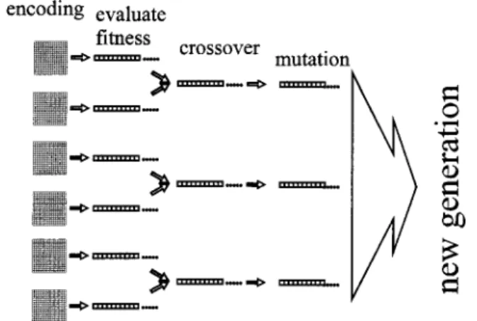
evolu-tionary principles in nature. The steps can be ex-plained in biological terms. As shown in Fig. 1, all possible modules are first encoded from codes called chromosomes. Second, the adaptive ability of the chromosomes to the circumstances are defined to evaluate the fitness of each chromosome. Third, a significantly large group of chromosomes is chosen to provide the crossover among each individual chromo-some and to add the probability of mutation in the course of producing offspring so as to produce a totally new chromosome. Finally, after several genera-tions, the surviving individual chromosome is the one that is the most adaptable to the existing environ-ment.

The following pseudocode itemizes the objects needed to simulate an optimization problem by mim-icking an evolutionary system:

1. Generate groups that are large enough to repre-sent different modules.

2. Define a function to describe the fitness of each individual chromosome to the environment in order to lay out the evolutionary rule.

3. Decide on a mechanism for chromosome muta-tion.

The algorithm is written as shown in Table 2. Examining the above-mentioned methods accord-ing to the traditional approach makes them appear quite different. Here we show the similarity of these two methods and prove that our newly developed GA with its preserving-the-best strategy possesses the sufficient and necessary condition for convergence. It should be noted that the word convergence is used in a pure mathematical sense, in which convergence means that the final value does not have any possi-bility of moving away from its current location through evaluation of the merit function, that is, the convergent value corresponds to the global optimum in a heuristic algorithm.

C. Mathematical Structures of the Genetic Algorithm and Simulated Annealing: Markov Chains

Basically the makeups of all SA and GA searches are all Markov chains.33,34 We can begin by defining the

limited searching spaceV, which in itself is a collec-tion of all possible configuracollec-tions. The symbol m is defined and set to measure the probability of finding solution X inV, and it is this probability distribution that we would like to converge on within the searches. For the best result of x0, we hope that m~x0! 5 1 and that all other configurations with

prob-ability distributions equal zero. Denoting the prob-ability of transition of y[ V to x [ V as p~y, x! and the probability distribution of the nth transition asnn yields

nn11~x! 5

(

y[Vnn~y!p~y, x!.

(1)

As nn approaches m when n approaches ` is the definition of convergence, we have

m~x! 5

(

y[Vm~y!p~y, x!

(2)

as an invariant35and a necessary condition for

con-vergence. However, because Eq. ~2! is difficult to prove, as we would need to assemble all the possible configurations, we can alternatively use the following reversible condition to guarantee the invariant con-dition state in Eq.~2!, where

m~y!p~y, x! 5 m~x!p~x, y!. (3)

Table 1. Pseudocode of a SA Method

Randomly produce the initial configuration, termed current config, and set up T

while~not thermal equilibrium! $

search the local neighborhood minimum, and see if replacing current config is needed.

Transition leads to new config

EvaluateD E 5 E~new config!2E~current config! If~DE , 0! replace current config by new config if~DE .5 0! set the probability of replacing

the current config by a new config5 exp@2DEyT#! Cool down to T by annealing schedule

%

Complete the cool down process, and print out the results.

Fig. 1. Sketch of the evolution of each generation in the GA.

Table 2. Pseudocode of a GA

Initialize population~random! for~i 5 1 to max generation!

$ evaluate fitness regenerate population

select parents crossover mutate population %

(4)

The statement in Eq.~3! can easily be proved by the combination of Eq.~3! and the constraint (yp~x, y! 5

1, yielding m~x! 5 m~x!

(

y p~y, x! 5

(

y m~x!p~y, x! 5

(

y m~y!p~y, x!. (4)

According to Eq.~2!, this is exactly the invariant. It can be easily proved that the Metropolis algo-rithm used in SA satisfies the reversible condition.36

More specifically, by use of H~x! as the merit function, #~V! as the number of V, Z as the normalization factor for (ym~y! 5 1, and T 5 T~n! as the temper-ature in the nth transition, it is essentially the same as having a family of probability distributions that satisfies the invariant condition but with a dynami-cally tuning variable T; that is,

p~x, y! 5 pT~x, y! 5 min@1, mT~y!ymT~x!#y#~V! for every y Þ x, (5) p~x, x! 5 pT~x, x! 5 1 2

(

yÞx pT~x, y!, (6) mT~x! 5 exp@2H~x!yT#yZ. (7)

As T gradually decreases to 0°, mT approaches m, where

m 5

H

10 for the best configuration x0

for other configurations . (8) If the random process converges, then it will con-verge to the best solution, such as when T5 0:

p0~x, y! 5 1, ifm~y! . m~x!, (9)

p0~x, y! 5 0, otherwise; (10)

the process will not have any chance to transit to a worst case. In this case, this process is similar to a common random search.

Another example that satisfies the reversible con-dition is the Gibbs sampler.36 The definition is

shown to be p~x, y! 5 $m~y!y@m~x! 1 m~y!#%y#~V! for every y Þ x, (11) p~x, x! 5 pT~x, x! 5 1 2

(

yÞx pT~x, y!. (12) For GA’s, if there are k chromosomes within each generation, the search will proceed in the space Vk, denoted as

X5 ~xi1, xi2, xi3, . . . , xik! [ Vk. (13) Because GA’s strive to select the best group within each generation to pass on to the chromosomes, X will not be unique. Such a group is defined as

Mxi5 $X [ V

kuthe best element in X is xi%. (14)

If the best chromosome is located at Mx0, the best

result x0 is obtained. Thus the transition can be

considered to proceed within U5 $Mxiuxi[ W%. Fol-lowing the same argument as shown with SA, the invariant is shown to be the necessary condition for convergence, i.e.,

m~x! 5

(

y[Vm~y!p~My

, Mx!, (15)

where p~My, Mx! is the transition probability. In contrast to the Metropolis algorithm for SA and the Gibbs sampler described above, the format and the mathematical structure of p~My, Mx! for the GA are complex and have not been clearly discussed before. It is required that, for the GA to converge to x0, the

condition must exist that m~x0! 5 1 and everything

else equals zero. Under this condition, Eq.~15! be-comes

m~x! 5 m~x0!p~Mx0, Mx!. (16)

If x Þ x0,m~x! 5 0 as shown above, then

p~Mx0, Mx! 5 0. (17) This is a necessary and required condition for the GA to converge. More specifically, this derivation indi-cates the probability that the transition from a best case to a worst case must be zero in order to guaran-tee convergence. Thus preserving the best is a nec-essary condition for convergence in the GA.

Even though the above derivations suggest only the preservation of x0and not the best of each

gen-eration, we in fact do not know which one is the best and thus need to identify it generation by generation. Therefore it is clear that preserving the best within each generation is a necessary condition for conver-gence. It should be stressed that the convergence mentioned here is used in a rigorous mathematical sense, that is, if the chromosome configuration has any possibility of moving away from its current posi-tion, in our case we do not consider it convergent. This is distinctly different from locating the local op-timum. More specifically, by convergence we mean locating the global optimum in the GA, which also corresponds to locating the global optimum for SA when T5 0.

The sufficient conditions for convergence can also be proved easily. As there are only finite mutation probabilities in the GA, the search mechanism within a GA is global. Thus it can also be said that the evolutionary history in V or U is ergodic. Because the space for searching is finite, the probability of missing x0is zero. Thus, given enough generations,

the preserving-the-best strategy can accurately lo-cate x0 and can possess the sufficient condition for

convergence.

If k5 1 in Eq. ~13!, then X of Eq. ~13! is x1, which

is identical to the x in Eq.~5! of SA. In addition, the transition possibility p~Mx, My! shown in Eq. ~15! reduces to p~x, y! in Eq. ~5!. Under this condition, the GA is quite similar to SA. If we adopt an extra parameter T as shown in Eq.~5!, the reduced GA will

(5)

turn into SA. Another thing that should be noted is that the preserving-the-best strategy cannot be adopted in this reduced GA as no progression will be possible. This certainly corresponds well with the common notion that no preserving-the-best strategy is useful or even feasible in SA.

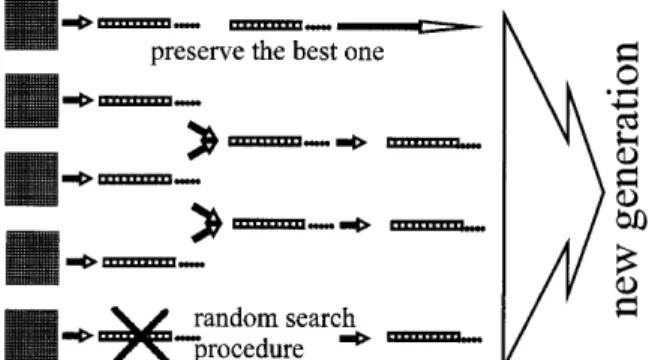
The above discussions clearly spell out that the preserving-the-best strategy can be used to modify the more conventional GA’s to guarantee conver-gence. One thing that should be noted is that, even though the more traditional GA’s may identify the best solutions, convergence cannot simply be guaran-teed without the adoption of the preserving-the-best strategy. More specifically, introducing the preserving-the-best strategy guarantees the possibil-ity of locating the global optimum. However, to pre-vent the searching algorithm from locking at a local minimum, a higher possibility of mutation can be introduced into the algorithm to prevent premature termination~Fig. 2!. In other words, if the possibil-ity of mutation is not large enough, introducing the preserving-the-best strategy might induce a prema-ture locking at a local optimum. This understand-ing provides us with an insight of what variables might be useful in ensuring that the global optimum is found, that is, introducing a higher possibility of mutation such as adding a random-search process into the preserving-the-best strategy~Figs. 2 and 3!

in the GA increases the chances of locating the global optimum. The drawback of this approach is that the iteration cycles will be longer in the beginning. One potential modification might be to increase gradually the possibility of mutation as the GA progresses to-ward global optimum.

Examining both SA and the GA from the Markov-chain viewpoint revealed the following: ~1! the in-variant condition, which guarantees that the global optimum can be reached, is readily available for SA, but is not clearly defined for the traditional GA;~2! the searching mechanism and the SA neighborhood are not clearly defined, which indicates that if the user cannot identify the most appropriate searching mechanism and neighborhood, SA can be consid-ered almost a random search; ~3! the chromosome crossover and population evolution rule for the tra-ditional GA clearly spells out the searching mech-anism and neighborhood required; and ~4! the preserving-the-best strategy makes the GA algo-rithm complete, as not only can the global optimum be reached, but also the searching mechanism and the neighborhood are readily available. The above-mentioned results indicate that if the user cannot easily or cleverly identify the searching mechanism and neighborhood of SA or even that of the Gibbs sampler, a GA should be the chosen algorithm. It is because of this understanding that only GA’s are applied to the design cases below.

3. Design Cases

A two-dimensional~2-D! phase fan-out grating was used as the test case to examine our numerical scheme. A 2-D phase fan-out grating is a combi-nation of two perpendicular one-dimensional grat-ings, whose structures are periodic in both directions. For the case in which the unit cell of the grating is an N3 N array ~Fig. 4! and each pixel of the unit is an element, in addition to M number of phase levels within each element, there will be a total of N2 power of M possible situations. The

phase level M is limited primarily by its fabrication capabilities.

Fig. 2. Graphic representation of the probability distribution of mutation for different GA’s: ~a! pure GA, ~b! modified GA, ~c! modified GA with a random-search procedure.

Fig. 3. Modified preserving-the-best strategy GA with a random-search procedure.

Fig. 4. Individual N3 N unit cell with an M-level phase for a self-repeating DOE.

(6)

If R represents convolutions, the transmittance of the DOE of interest can be written as

t~x, y! 5

(

m52` `

(

n52` ` d~x 2 mN, y 2 nN! ^

(

p50 N21

(

q50 N21 rect~x 2 p, y 2 q!exp~ifpq!, (18) where d is the Dirac delta function, rect~x, y! 5 rect~x!rect~y!, and

rect~x! 5

H

1 0

uxu # 0.5

otherwise. (19) By the scalar-wave diffraction theorem, the Fraun-hofer diffraction can be written as a discrete Fourier transform.37 The Fourier series of t~x, y! is

T~m, n! 5 sinc~myN, nyN!

(

p50 N21

(

150 N21 exp~ifpq! 3 exp@2i2p~mpyN 1 nqyN!#, (20) where sinc~x, y! 5 sinc~x!sinc~y!, sinc~x! 5 sin~px!y px, and uT~m, n!u2is the intensity of diffraction order

~m, n!.

Considering the case in which the incident light beams have a flat wave front and a flat intensity level, we can use the mean-square error ~MSE! to examine the difference between desired intensity I~m,

n! and uT~m, n!u2. More specifically, as a user tends

to worry about only a small number of diffractive orders, the MSE is quite suitable to examine the closeness of experimental and theoretical results of DOE’s, where

MSE5 1

#~D!~m, n![D

(

uI~m, n! 2 guT~m, n!u

2u, (21)

and #~D! is the number of elements in D. After re-gression analysis, the linear correlation coefficientg between I~m, n! and uT~m, n!u2 is derived to be an

index of the correlation and can be explicitly written as

g 5 ~m, n![D

(

~I 2 Iavg!~uTu22 uTuavg2 !

F

~m, n![D

(

~I 2 Iavg!2

G

1y2

F

~m, n![D

(

~uTu22 uTu avg 2 !2

G

1y2, (22) where IavganduTuavg

2

are the mean values of I anduTu2, respectively.

In fact, when the scalar-wave theorem is used, the whole problem can be simplified to a phase problem37

and the amplitude distribution on the image plane can be written as F~kx, ky! 5

*

2` `

*

2` ` U~x, y!exp@if~x, y!# 3 exp@2i~kxx1 kyy!#dxdy, (23)

where kxand kyare the wave numbers in the x and the y directions, respectively, F~kx, ky! is proportional to the diffraction field, and U~x, y! and f~x, y! repsent light amplitude and phase on the elements, re-spectively. The main idea behind designing a phase-type DOE is to find the phase and the ampli-tude distribution solution to each given intensity dis-tribution functionuF~kx, ky!u2. The solutions to these

inverse calculation problems, seen in many fields,38

are acceptable and comprehensive in some special cases. However, even in cases in which a solution exists, an easier and more efficient calculating method to find such the solution is highly desirable. For a 2-D periodic structure, the solution will not be unique and will depend on detailed information.39

More specifically, if there are more constraints added, such as a Gaussian distributed light source or a lim-itation of the feature size during fabrication, mathe-matical analysis becomes more complicated and the meaning behind the solution more obscure. Now, with our self-repeating units, we can simplify DOE’s of interest to the greatest extent in order not to ob-scure the fundamental meaning behind DOE’s.

According to the problem stated above, it appears that a proper heuristic algorithm is required for ac-complishing the task. GA’s and SA, the two most important heuristic algorithms, are also two of the most commonly used direct search methods in de-signing a DOE. For the reasons stated below, a GA instead of SA was used in the design of our DOE.

The merit of SA is its ability to search for the best solution among all configurations. Thus the system has opportunities to bypass the local-minimum state and can eventually reside at the global minimum following the Boltzmann distribution. However, SA finds a solution merely according to the predefined energy function and does not consider any informa-tion related to real problems known beforehand, i.e., SA can search out a better solution only passively. On the other hand, a GA tends to find a better solu-tion in every generasolu-tion. More specifically, a GA contains an implicitly parallel processing spirit while evolving within the group. A GA preserves elegant chromosomes from parents to children and improves the quality in advance to reach an optimal conse-quence.8,40 Thus we chose a GA to formulate and

implement our design, which led to our DOE design as related in Eq.~20!.

The aim of our design was to create a unit cell consisting of a 16 3 16 element array with phase levels p and 0 that can generate an output-energy distribution according to the 73 7 diffraction image specified in Table 3.

Because our design employs a two-level grating, the transmittance t~x, y! in Eq. ~18! is a real number and the intensity distribution generated will be nat-urally centered symmetrically after the Fourier transform.

A. Parameters and Relevant Strategies

Referring to the pseudocode of the GA listed in Table 2, we arbitrarily initiated a population of 32 unit

(7)

cells. These unit cells, which are a set of 16 3 16 arrays and are quantified by random phases of 0 orp, are used as the incipient group. From there, we then started the 2000-generation search from the ini-tial group. The method used to evaluate the fitness within each evolution is the MSE identified in Eq. ~21!. The output domain D is exactly the central 7 3 7 diffraction image array. Described below are the four methods we applied to identify and obtain the results.

1. Pure Genetic Algorithm

The method to generate the subsequent generation and the way the mutations occurred are described below ~see Fig. 2!. First, the parents were selected and the chromosomes ranked within the group ac-cording to fitness in order to decide the opportunity of generating children by a certain probability distribu-tion. The utilized probability distribution Prob~i! was chosen to be a binomial distribution, i.e., Prob~i! 5 q~1 2 q!i21, where i is a positive integer. At each

generation, coupled parents produced a new genera-tion of chromosomes according to its probability. The breeding method was effectively a multipoint method in which every element in the chromosome generated was chosen randomly from among the el-ements in the same place of the two mating chromo-somes. One thing that should be noted is that, because the sum of the finite terms

(

i51N q~1 2 q!i215 q@1 2 ~1 2 q!N#y@1 2 ~1 2 q!# 5 1 2 ~1 2 q!N

(24) can never equal 1, a term of probability~1 2 q!Nmust be added in. Thus the possibility of mutation was chosen to be 2y~16 3 16! i.e., 1y128.

2. Modified Preserving-the-Best Strategy Genetic Algorithm

With this methodology, the selection of the parents, the production of the children, and the possibility of mutation are all identical to that of the pure GA. However, the best chromosomes will be completely preserved for new generations in this algorithm. In our particular case, only 31 new chromosomes needed to be generated.

3. Modified Preserving-the-Best Strategy Genetic Algorithm with a Random-Search Procedure

This algorithm is almost the same as the modified GA mentioned above, except that a random-search pro-cedure was added. This algorithm not only acquired random terms to generate the new generations, but it also necessitated the addition of some random gen-erating chromosomes to each new generation~Fig. 3!. This method corresponds to making the possibility of mutating the second to the twenty-sixth best chro-mosome to equal 1y128 and the possibility of mutat-ing the last five worst chromosomes to equal 1 ~Fig. 2!. As was stated above, combining the preserving-the-best strategy and increasing the possibility of chromosome mutation into the traditional GA will both guarantee convergence and reduce the possibil-ity of premature locking at the local optimum. The introduction of the random-search procedure agrees well with this understanding. However, the num-ber of random-search chromosomes should be chosen with care, as the modified GA will become a brainless random-search process if all but the best chromo-somes are replaced when the random-search process is used. In the example shown, five random initiat-ing chromosomes were added, makinitiat-ing a total of only 26 new chromosomes that remained to be passed on from the initial parents.

4. Modified Preserving-the-Best Strategy Genetic Algorithm Eight-Level Element

This method is the same as that of Subsection 3.A.2, except that the phase is an eight-level phase i.e., $7py4, 3py2, 5py4, p, 3py4, py2, py4, 0%.

B. Numerical Results

The results of all four methods described above are summarized in Fig. 5, in which the x axis is the generation number and the y axis is the merit func-tion that is proporfunc-tional to the negative value of the MSE.

The numerical values of the diffractive image in-tensity are shown in Table 4. For comparison with the design goals listed in Table 3, the linear correla-tion coefficient@see Eq. ~22!# g 5 0.9795. As we can see, g is very close to 1. This experimental result indicates that the design target has been met. Meanwhile, the design unit cell of the 2-D phase fan-out grating is shown at the top of Fig. 6, and the bottom shows the amplitude-type fan-out grating

Table 3. 73 7 Diffraction Image Arraya

myn 23 22 21 0 1 2 3 23 0 0 0 0 0 0 0 22 0 C 0 0 0 B 0 21 0 0 0 A 0 0 0 0 0 0 0 0 0 0 0 1 0 0 0 A 0 0 0 2 0 B 0 0 0 C 0 3 0 0 0 0 0 0 0

(8)

that can be transferred to the fabrication process. All calculations were executed on a 133-MHz Pen-tium CPU PC with Microsoft Windows NT as the operating system. This example produced 2000 gen-erations and took 3704 s even before the fast Fourier-transform algorithm was adopted to speed up the process. As the Fourier-transform computation was located within four nested loops, the computation speed definitely benefited from the adoption of the fast Fourier transform. It is also clear from Fig. 5 that the modified preserving-the-best strategy GA with a random-search procedure progressed to the final accepted configuration within less than 200 gen-erations, which corresponds to less than 370 s of com-putation time. This result is quite acceptable for running the algorithm in a simple Pentium PC envi-ronment.

Another example required that we design a 643 64 pixel grating according to a given 9 3 9 diffraction image. We produced 5000 generations in the same way as in the example above and spent 233,617 s to obtain the results. The linear correlation coefficient g was found to be further enhanced to 0.9838, and this was a marked improvement toward the linear correlation coefficient.

4. Fabrication

The quality of a fabricated DOE is highly influenced by the processing equipment conditions. Further-more, the design freedom of a DOE is also limited by equipment capabilities, such as feature size. We used a commercially available imagesetter, Agfa Su-perSelect 7000, to produce the binary pattern. Its fine, clear, output feature size was in the range of 30 mm. A 103 photoreduction system was used to gen-erate a reticle to serve as a mask for photolithogra-phy. The film was also used directly as a reticle mask.41

Our intention in this paper was not to focus on processing accuracy or comparison with products generated from more advanced fabrication facilities. Here only the design concepts are discussed.

A. Photoreduction

The calculated results of our unit cell were generated by an illustration program from the Aldus Corpora-tion. Aldus FREEHANDuses its tile function to

gener-ate repeating patterns of various desired sizes. This Fig. 5. Numerical results obtained with a GA to design a fan-out

grating: ~1! modified GA, level element; ~2! pure GA, two-level element;~3! modified GA with a random-search procedure: two-level element;~4! modified GA, eight-level element.

Table 4. Numerical Results of the Diffraction Image Intensity Obtained with a GA

myn 23 22 21 0 1 2 3 23 4.3 13.0 3.2 89.8 22.2 17.5 16.1 22 1.6 5392.9 26.1 13.0 13.0 7187.5 7.7 21 9.0 14.5 76.1 3919.2 15.8 2.3 8.2 0 10.8 61.1 8.0 16.0 8.0 61.1 10.8 1 8.2 2.31 15.8 3919.2 76.1 14.5 9.0 2 7.7 7187.5 13.0 13.0 26.1 5392.9 1.6 3 16.1 17.5 22.2 89.8 3.2 13.0 4.3

(9)

file was transferred to a commercially available im-agesetter, Agfa SuperSelect 7000, to produce a film with our desired pattern.9 For the purpose of our

103 photoreduction, a green cold-light illuminating panel made of ZnS with less than 3% illumination nonuniformity was used, and a Kodak plate was se-lected to be the replica.

B. Photolithography

A Karl Suss g-line direct-contact aligner was used to expose our photoresist ~e.g., Fujihunt 6400L! of choice, which was coated onto glass. After many standard development procedures, a pattern con-structed by the photoresist was found to have a 0.7-mm-deep feature.

Basically an anisotropic dry etch of reactive ion etching can be applied to obtain a precise relief depth. However, to just show only the advantages of the design concept, a transparent binary pattern of pho-toresist on glass can serve as a phase-type fan-out grating for beam light redistribution.

5. Measurements

Diffractive beam light intensity was the object to be measured. The experimental layout ~Fig. 7! shows that the laser light was introduced to a spatial filter composed of an object lens and a pinhole. The pin-hole position was positioned to the focus of the mi-croscope lens so that the expanded laser light did not move. The collimated light passing through the fan-out grating redistributed the beam to the designed pattern, after which a photodetector was used to de-tect the diffractive light intensity at each spot.

A shear plate42was used to ensure that the

colli-mated light was indeed in parallel. We used a sim-ple interferometer, an optical arrangement in which wedged plates were used to produce a graded path

difference between the front and the back surface reflections. Consequently a parallel beam of light produced a linear fringe pattern where the reflections overlapped.

The measured results of the fan-out intensity dis-tribution are shown in Table 5. Values shown at~0, 0! indicate the zeroth-order term. The linear corre-lation coefficientg was 0.9775 when the zeroth-order term was neglected. The experimental results show that the intensity of the zeroth-order term deviated from the design value. However, this deviation can be explained by the surface-relief depth. As the pro-gram calls for a He–Ne laser, a wavelength of 632.8 nm was used. The Fujihunt photoresist was found to have a refractive index of np5 1.64 at 632.8 nm. The correct etch depth, which corresponds to the half-wavelength difference, should be 0.49 mm @5~632.8 nmy2!y~np2 1!#. Our fabricated DOE had an etch depth of 0.7 mm, which corresponds to a 42% error. However, despite such a large etch-depth difference variation, only the zeroth-order light distribution was found to have variations.

As the zeroth-order term was neglected, the exper-imentally measured value of a 0.9795 linear correla-tion coefficient agrees well with the theoretically predicted linear correlation coefficient of 0.9775.

In fact, it can be proved that, for a binary element with a phase value of$0, p%, the former denotes region A and the latter region B. If there is a phase errorD generated during fabrication, in general it can be safely assumed that the individual phase errors for each region are exp~iDy2! and exp@i~p 2 Dy2!#, re-spectively.

It is known that the intensity equals the squared term of the field, and the design field for the kth order is defined as follows:

F~kx, ky! 5

**

A

exp~i0!exp@2i~kx1 ky!#dxdy

1

**

B

exp~ip!exp@2i~kx1 ky!#dxdy

5

**

A

exp~2i@kx1 ky!#dxdy

2

**

B

exp@2i~kx1 ky!#dxdy. (25) Fig. 7. Layout for diffractive power measurement.

Table 5. Intensity Distribution of the Designed DOE (in Nanowatts)

myn 23 22 21 0 1 2 3 23 3 2 10 5 7 10 2 22 7 1428 10 10 28 1957 18 21 5 7 12 907 20 79 23 0 2 15 41 9248 46 20 5 1 18 78 12 953 30 7 5 2 15 1898 12 10 23 1480 12 3 2 15 5 5 12 15 18

(10)

The actual field can be expressed as

F˜ ~kx, ky! 5

**

A

exp~iDy2!exp@2i~kxx1 kyy!#dxdy

1

**

B

exp@i~p 2 Dy2!# 3 exp@2i~kxx1 kyy!#dxdy 5 cos~Dy2!$

**

A ~1!exp@2i~kxx1 kyy!#dxdy 1

**

B ~21!exp@2i~kxx1 kyy!#dxdy% 1 i sin~Dy2!

H

**

A exp@2i~kxx 1 kyy!#dxdy 1

**

B exp@2i~kxx 1 kyy!#dxdy

J

5 cos~Dy2!F~kx, ky! 1 i sin~Dy2!d~kx, ky!, (26) whered is the Dirac delta function and

F˜ ~kx, ky! 5 cos~Dy2!F~kx, ky!

except when kx5 ky5 0, (27) that is, for a parallel incident light, the error of a surface-relief depth of a binary DOE will only induce phase error. The surface relief will not influence the intensity ratio of any order except that of the zeroth-order term.

6. Conclusions

An efficient design methodology for DOE’s formed by self-repeating patterns can be generated by a modi-fied preserving-the-best strategy of GA’s. Mathe-matical arguments are provided to show that the preserving-the-best strategy has the sufficient and necessary condition for GA’s to converge.

A stochastic process was used to examine the sim-ilarity between GA’s and SA. The insights gener-ated from this analysis provide us with a way to code these two algorithms in an almost identical manner. Such an approach makes the coding of various heu-ristic algorithms easy to develop and easy to debug. In addition, the fundamental understanding gener-ated provides us with a way to adjust intelligently the tuning parameters typically found in various heuris-tic algorithms. Four numerical approaches, the GA’s for a binary element, the original GA for a bi-nary element, the modified preserving-the-best GA for a binary element, and the modified

preserving-the-best GA for an eight-level element, were used to examine the efficiency of these algorithms. The modified preserving-the-best GA for a binary element was identified to be most efficient in terms of compu-tational time.

Because a simple development platform based on the IBM PC-compatible system was used in the de-sign process, a simple semiconductor process was then adopted to fabricate the DOE’s designed. The etching depth was shown not to influence the energy distribution ratio of all nonzero diffractive orders of binary DOE’s. This understanding significantly re-duces the etching requirement for surface-relief types of DOE’s. Experimental results were shown to agree well with theoretical predictions.

This article was partially supported by the Na-tional Science Council of Taiwan, China, under project numbers NSC 84-2622-E-002-007 and NSC 85-2622-E-002-017R. The authors thank H. W. Lee for helping us to measure the refractive index of the Fujihunt 6400 photoresist at 632.8 nm. In addition, thanks goes to Julie Lee for her invaluable sugges-tions and editing to make sure that the accurate meanings were conveyed.

References

1. J. N. Mait, “Understanding diffractive optic design in the sca-lar domain,” J. Opt. Soc. Am. A 12, 2145–2158~1995!. 2. F. Wyrowski, “Design theory of diffractive elements in the

paraxial domain,” J. Opt. Soc. Am. A 10, 1553–1561~1993!. 3. M. A. Seldowitz, J. P. Allebach, and D. W. Sweeney, “Synthesis

of digital holograms by direct binary search,” Appl. Opt. 26, 2788 –2798~1987!.

4. J. R. Fienup, “Iterative method applied to image reconstruc-tion and to computer-generated holograms,” Opt. Eng. 19, 297–306~1973!.

5. B. K. Jennison, J. P. Allebach, and D. W. Sweeney, “Iterative approaches to computer-generated holography,” Opt. Eng. 28, 629 – 637~1989!.

6. J. Turunen, A. Vasara, and J. Westerholm, “Kinoform phase relief synthesis: a stochastic method,” Opt. Eng. 28, 1162– 1167~1989!.

7. M. R. Feldman and C. C. Guest, “High-efficiency hologram encoding for generation of spot arrays,” Opt. Lett. 14, 279 – 481 ~1989!.

8. D. E. G. Johnson, A. D. Kathman, D. H. Hochmuth, A. L. Cook, D. R. Brown, and B. Delaney, “Advantages of genetic algorithm optimization methods in diffractive optic design,” in Diffractive

and Miniaturized Optics, S. H. Lee, ed., Vol. CR49 of SPIE

Critical Reviews, Bellingham, Wash., 1993!, pp. 54–74. 9. R. W. Gerchberg and W. D. Saxton, “A practical algorithm for

the determination of phase from image and diffraction plane pictures,” Optik 35, 237–246~1972!.

10. N. C. Gallagher and B. Liu, “Method for computing kinoforms that reduces image reconstruction error,” Appl. Opt. 12, 2328 – 2335~1973!.

11. F. Wyrowski and O. Bryngdahl, “Iterative Fourier-transform algorithm applied to computer holography,” J. Opt. Soc. Am. A

5, 1058 –1065~1988!.

12. F. Wyrowski, “Diffractive optical elements: iterative calcula-tion of quantized, blazed phase structures,” J. Opt. Soc. Am. A

7, 961–969~1990!.

13. F. Wyrowski and O. Bryngdahl, “Digital holography as part of diffractive optics,” Rep. Prog. Phys. 54, 1481–1571~1991!. 14. D. E. Goldberg, Genetic Algorithms in Search, Optimization,

(11)

and Machine Learning ~Addison-Wesley, Reading, Mass.,

1989!, Chap. 4, pp. 125–129.

15. J. H. Holland, Adaptation in Natural and Artificial Systems ~MIT, Cambridge, Mass., 1992!, Chap. 1, pp. 1–19.

16. L. Davis, Genetic Algorithms and Simulated Annealing ~Pit-man, London, 1987!, Chap. 1, pp. 1–11.

17. D. Brown and A. Kathman, “Multi-element diffractive optical designs using evolutionary programming,” in Diffractive and

Holographic Optics Technology II, Ivan Cindrich and S. H. Lee,

eds., Proc. SPIE 2404, 17–27~1995!.

18. S. Kirkpatrick, C. D. Gelatt Jr., and M. P. Vecchi, “Optimiza-tion by simulated annealing,” Science 220, 671– 680~1983!. 19. M. S. Kim and C. C. Guest, “Simulated annealing algorithms

for binary phase only filters in pattern classification,” Appl. Opt. 29, 1203–1208~1990!.

20. W. H. Press, B. P. Flannery, S. A. Teukolsky, and W. T. Vet-terling, Numerical Recipes: The Art of Scientific Recipes

~Cambridge U. Press, New York, 1986!, Chap. 10, pp. 326–334. 21. D. C. O’Shea, J. W. Beletic, and M. Poutous, “Binary mask generation for diffractive optical elements using microcomput-ers,” in Diffractive Optics: Design, Fabrication, and Applica-tions, Vol. 9 of 1992 OSA Technical Digest Series ~Optical

Society of America, Washington, D.C., 1992!, pp. 114–116. 22. T. J. Suleski and D. C. O’Shea, “Fidelity of

PostScript-generated masks for diffractive optics fabrication,” Appl. Opt.

34, 627– 634~1995!.

23. D. C. O’Shea, T. K. Gaylord, J. N. Mait, and A. Kathman, “Course notes,” presented at the Diffractive Optics workshop, Georgia Institute of Technology, Atlanta, Georgia, 21–24 March 1995.

24. M. G. Moharam and T. K. Gaylord, “Rigorous coupled-wave analysis of planar-grating diffraction,” J. Opt. Soc. Am. 71, 811– 818~1981!.

25. T. K. Gaylord and M. G. Moharam, “Analysis and application of optical diffraction gratings,” Proc. IEEE 73, 894 –937~1985!. 26. M. G. Moharam and T. K. Gaylord, “Rigorous coupled-wave analysis of metallic surface-relief gratings,” J. Opt. Soc. Am. A

3, 1780 –1788~1986!.

27. E. N. Glytsis and T. K. Gaylord, “Rigorous three-dimensional coupled-wave diffraction analysis of single and cascaded aniso-tropic gratings,” J. Opt. Soc. Am. A 4, 2061–2080~1987!.

28. R. Magnusson and T. K. Gaylord, “Equivalence of multiwave coupled-wave theory and modal theory of periodic-media dif-fraction,” J. Opt. Soc. Am. 68, 1777–1779~1978!.

29. M. G. Moharam and T. K. Gaylord, “Formulation for stable and efficient implementation of rigorous coupled-wave analysis of binary gratings,” J. Opt. Soc. Am. A 12, 1068 –1076~1995!. 30. G. Granet and B. Guizal, “Efficient implementation of the

coupled-wave method for metallic lamellar gratings in TM polarization,” J. Opt. Soc. Am. A 13, 1019 –1023~1996!. 31. E. Johnson, M. A. G. Abushagar, and A. Kathman, “Phase

grating optimization using genetic algorithms,” in Optical

De-sign for Photonics, Vol. 9 of 1993 OSA Technical Digest Series

~Optical Society of America, Washington, D.C., 1993!, pp. 71– 73.

32. E. Aarts and J. Korst, Simulated Annealing and Boltzmann

machines,~Wiley, New York, 1989!, Chap. 2, pp. 13–14.

33. J. H. Holland, Adaptation in Natural and Artificial Systems, ~MIT, Cambridge, Mass., 1992!, Chap. 3, pp. 49–52.

34. Ref. 32, Chap. 3, pp. 49 –52.

35. S. M. Ross, Stochastic Process~Wiley, New York, 1983!, pp. 100 –111.

36. D. Geman, “Random fields and inverse problems in imaging,” in Proceedings of the E´ cole d’E´te´ de Probabilite´s de Saint-Flour XVIII–1988, Lecture Notes in Mathematics, Vol. 1427, ~Springer-Verlag, New York, 1991!, pp. 113–193.

37. J. W. Goodman, Introduction to Fourier Optics, 1st ed. ~McGraw-Hill, New York, 1992!, Chap. 4, pp. 57–70. 38. M. Nieto-Vesperinas, Scattering and Diffraction in Physical

Optics~Wiley, New York, 1991!, Chap. 10, pp. 341–376.

39. P. Millane, “Phase problems for periodic images: effects of support and symmetry,” J. Opt. Soc. Am. A 10, 1037–1045 ~1993!.

40. Ref. 14, Chap. 2, pp. 27–57.

41. P. S. Levin and L. H. Domash, “MacBeep: a desktop system for binary optics,” in Diffractive Optics: Design, Fabrication, and Applications, Vol. 9 of 1992 OSA Technical Digest Series

~Optical Society of America, Washington, D.C., 1992!, pp. 120– 122.

42. “Lasers and instruments guide,” B.5, 12–16, Melles Griot Corp., 4665 Nautilus Court, South Boulder, Colorado~1994!.

數據

Table 1. Pseudocode of a SA Method Randomly produce the initial configuration, termed current config, and set up T
Fig. 4. Individual N 3 N unit cell with an M-level phase for a self-repeating DOE.
Table 3. 7 3 7 Diffraction Image Array a
Fig. 6. Fan-out grating designed with a GA.
+2

參考文獻

相關文件

In this work, for a locally optimal solution to the nonlin- ear SOCP (4), under Robinson’s constraint qualification, we show that the strong second-order sufficient condition

The algorithms have potential applications in several ar- eas of biomolecular sequence analysis including locating GC-rich regions in a genomic DNA sequence, post-processing

Is end-to-end congestion control sufficient for fair and efficient network usage. If not, what should we do

important to not just have intuition (building), but know definition (building block).. More on

• A school with teachers strong in science can strengthen the learning of science and technology elements in GS by promoting reading in science and providing ample opportunities

For meeting the requirement in aggregate usage and maximizing utilization ratio of E&R resources obtained from the site, this study tried to adjust the optimum

The proposed algorithms use the optimal-searching technique of genetic algorithm (GA) to get an efficient scheduling solution in grid computing environment and adapt to

This purpose is to develop time-domain numerical algorithms for modeling electromagnetic wave interactions with linear and nonlinear optical gain media, as well