Y.-S. Ho and H.J. Kim (Eds.): PCM 2005, Part II, LNCS 3768, pp. 841–853, 2005. © Springer-Verlag Berlin Heidelberg 2005
Up-Conversion and Adaptive Frame Encoding
Ya-Ting Yang1, Yi-Shin Tung2, Ja-Ling Wu1,2, and Chung-Yi Weng11
Department of Computer Science and Information Engineering, National Taiwan University
2
The Graduate Institute of Networking and Multimedia, National Taiwan University {ytyang, tung, wjl, chunye}@cmlab.csie.ntu.edu.tw
Abstract. Frame rate up-conversion (FRUC) is a useful technique for a lot of
practical applications, such as display format conversion, low bitrate video cod-ing and slow motion playback. Unlike traditional approaches, such as frame repetition or linear frame interpolation, motion-compensated frame interpola-tion (MCFI) technique which takes block mointerpola-tion into account is regarded as a more efficient scheme. By considering the deficiencies in previous works, new criteria and coding schemes for enhancing motion derivation and interpolation processes are suggested. We then integrate the proposed MCFI scheme into the decoding process of the latest coding standard, H.264/AVC. In addition, adap-tive frame skip is fulfilled at the encoder side to maximize the power of MCFI in video coding applications. As a result, the encoder can adopt the MCFI dy-namically and can decide whether the input frame should be coded or dropped then interpolated. Experimental results show that our proposal indeed enhances the overall quality, both subjectively and objectively, especially for the low bi-trate video coding.
Keywords: Frame Rate Up-Conversion, Motion Compensated Frame
Interpola-tion, Adaptive Frame Skip.
1 Introduction
The popularity of advanced television and multimedia information systems has caused a rapid increase in the number of video sources and variety of display formats. This has resulted in a demand for converting between various formats efficiently. In contrast with super-resolution video reconstruction [1], frame rate up conversion (FRUC), as implied by the name, is a process to convert the video frame rate from a lower number to a higher one. When a video sequence is encoded to a certain com-pression ratio, frame interpolation technique (FIT) is always used as a post-processing tool to reconstruct the skipped frames. FIT reduces the temporal jerkiness by repre-senting video at any desired frame rate (even to the full frame rate) on the basis of interpolation techniques.
The development of FRUC potentiates a lot of video applications. The most prac-tical one, probably, is to enhance the reconstructed quality of a low bitrate coded video. For example, in the video conferencing applications, it is inevitable for an encoder to have a number of frames skipped. A temporal interpolation is then helpful
to smooth over those discontinuities. Besides these applications, FRUC can also bene-fit slow-motion playback by synthesizing those inexistent intermediate frames for smoothing slow motion playback. Other well-known applications include PAL-NTSC conversion and the video editing. FRUC may also impact on the rate allocation policy of a scalable video coding scheme.
Conventional FRUC approaches (such as frame repetition and linear frame inter-polation) did not take motion information into account. As long as the video sequence has large or complex motion, those approaches may fail, and annoying artifacts such as motion jerkiness or image blur may appear. In recent researches [2-10], the motion-compensated frame interpolation (MCFI) scheme is widely adopted. MCFI enhances the reconstruction video quality by exploring block motions of interpolated frames.
Although MCFI is a post-processing tool at the decoder end, it still has something to do with the encoder. Since the activity of the object movement often varies from time to time, adaptive frame skip is performed to overcome the shortage that the video quality of FRUC is seriously constrained by the information provided by the encoder. When the object motion is slower and more linear-like, we may skip more frames between two coded frames. Otherwise, the number of skipped frames should be kept small. Adaptive frame skip (AFS) scheme was also presented in [10], where a suitable skipping number is selected from a pre-defined set. Inspired by [10] and observed from our simulation results, we found that there is still large room for enhancing the performance of FRUC with the aid of AFS.
The remainder of this paper is organized as follows. Section 2 gives an overview of MCFI. A system framework of the adopted MCFI process is presented in Section 3. Next, in Section 4 our implementation of AFS in the encoder end is ad-dressed. Experimental results and discussions are given in Section 5. Finally, Section 6 concludes this write-up.
2 An Overview of Motion Compensated Frame Interpolation
(MCFI)
Video sequences usually contain a huge amount of temporal redundancy that can be exploited for coding and processing purposes. Motion estimation and motion compen-sation are powerful means for exploiting such redundancy and are used in most ad-vanced video coding standards. Although the concept of MCFI is similar to the bidi-rectional prediction mode of B-frame in all prevalent coding standards, the applica-tion of MCFI is different from that of the bidirecapplica-tional predicapplica-tion since the moapplica-tion fields of the interpolated frame are not estimated at the encoder and transmitted to the decoder. The success of MCFI depends on how well the real motion vector can be obtained since there is no residual information favoring the reconstruction of those skipped frames. Once the motion vectors are incorrect, block artifacts will be intro-duced thereafter. Therefore, it is crucial 1) to correctly evaluate the reliability of the motion vectors no matter the motion vectors are derived from block-based motion fields within the bitstream or obtained from the re-estimation process, and 2) to esti-mate true motion vectors efficiently if the motion description is not available or not appropriate.
The main assumption of MCFI is that: there is a linear object translation within a short time period. In the case of 1:2 up conversion, the motion of the interpolated frame is V/2 to the previous frame and –V/2 to the current frame, where V is the mo-tion from the current frame to the previous one. A bidirecmo-tional interpolamo-tion is intro-duced to synthesize the in-between frame, and therefore, each pixel in the interpolated frame is generated by combining the corresponding pixels in the forward and the backward reference frames. In other words, the values of the interpolated pixels should be: ( , 1) ( , ) 1 2 2 ( , ) 2 2 v v f x t f x t f x t + − + − − = , (1)
where f(x,t) denotes the pixel value at location x and in time t.
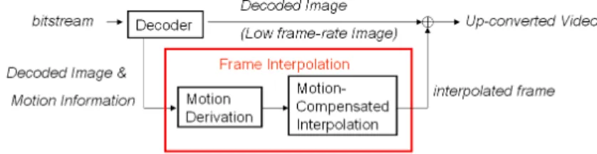
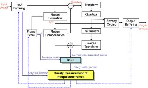
In addition, Fig. 1 reveals the general framework to cooperate FRUC with the MPEG decoding process. It fulfills interpolation independently of the encoder except for the use of block motion vectors provided by the encoder. By utilizing the embed-ded motion information and the reconstructed frames in the MPEG decoding process, MCFI can be done efficiently due to the significant decrease of computation of mo-tion estimamo-tion. Finally, the decoded frames and interpolated frames are multiplexed to form an up-converted video. However, the precision of the available motion vec-tors limit the quality of interpolation, so it is essential to identify unreliable motion vectors and fine-tune them further.
Fig. 1. A generic flowchart to integrate FRUC with the MPEG decoding process
3 System Framework of MCFI
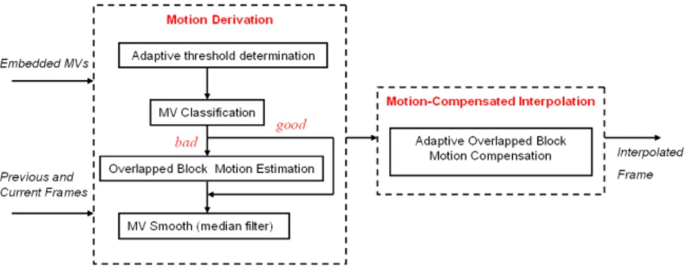
The major components of our frame interpolator include motion derivation and
mo-tion-compensated interpolation, as shown in Fig. 2. The purpose of motion derivation
is to obtain accurate motion vectors such that motion-compensated interpolation can perform well since the performance of MCFI depends significantly on the motion vector accuracy. In the motion derivation process, motion vectors embedded in the bitstream are extracted and then classified adaptively into a bad or good category first. If the motion vector is not available or has been categorized into the bad group, over-lapped block bi-directional motion estimation (OBME) is performed. A median filter to eliminate the discontinuities and to smooth the motion fields in the neighboring blocks is then applied. Finally, motion vectors of all blocks are generated, and adap-tive OBMC is employed to obtain the to-be-interpolated frames.
Fig. 2. The flowchart of the proposed MCFI approach
3.1 Obtaining Motion Vectors of the Interpolated Frame
Before realizing the process of MCFI, we first determine some basic characteristics, e.g. the resolution of a motion vector and the block size, of the interpolated frame. Clearly, small block sizes aim to minimize the residual energy, while large block sizes intend to get more true motion vectors. Under these considerations, 8×8 block size is selected as the basic processing unit to trade off the energy reduction of residual im-ages and the correctness of obtained motion vectors. Further, state-of-the-art video coding standards support variable block sizes, e.g. MPEG-4 Visual supports motions for individual 8×8 and 16×16 blocks and H.264/AVC allows motions from 4×4 to 16×16 blocks. In those cases, we must split and merge different block sizes to form a motion vector for each 8×8 block. If the block size is larger than 8×8, each 8×8 sub-block derives its motion vector from the original large sub-block. Otherwise, if the sub-block size is smaller than 8×8, the motion vector can be obtained by averaging motion vec-tors of all its subblocks. Next, if the block is encoded in the INTRA mode, motion estimation has to be performed in a later stage. In our implementation, for retaining the motion vector resolution and utilizing its effectiveness, a 6-tapped quarter-pel filter and an eighth-pel bilinear filter are adopted for luminance and chrominance interpolations, respectively. As far as the motion vector accuracy and fractional sam-ple interpolation are concerned, our realization compliantly follows the specification of the adopted coding standard (H.264/AVC in our case), so as to preserve the coding efficiency and the prediction accuracy of received motion vectors.
3.2 Motion Vector Classification
It is the fact that the block motion vectors generated in the encoder are for compres-sion purpose but not for obtaining the real motion of objects. As a result, even motion vectors are available at the decoder side, not all of them are really close to the true motions and a re-estimation for those blocks with unreliable motion vectors is of necessity. To eliminate the unnecessary computation, a reliable classification for all available motion vectors becomes critical. It is well known that the sum of absolute difference (SAD) can be used to measure the signal similarity between two blocks in their supporting regions (8×8 in our case) and the boundary absolute difference
(BAD) can be used to measure the connecting smoothness between the interior and the exterior of block boundaries. So we consider SAD as well as BAD simultaneously and compare them with some content-adaptive thresholds, which will be addressed later.
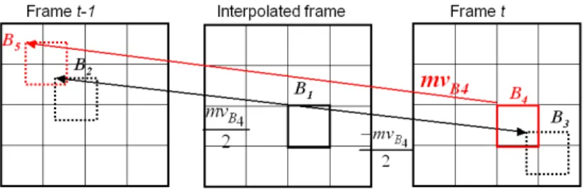
For a block, e.g. B1, in the interpolated frame, we first find the co-located block,
B4, in the current frame (frame t) and employ its motion, mvB4, to obtain the blocks B2 and B3 respectively in the previous (frame t-1) and the current frames with the same motion trajectory, as shown in Fig. 3. For example, if the interpolated frame is right in the middle of the previous and the current frames, the motion vectors pointing to B2 and B3 are mvB4/2 and -mvB4/2, respectively. Then, we calculate SADB1 and BADB1, i.e. the SAD and the BAD between B2 and B3, as follows:
2 2 3 2 2 3 2 2 3 2 2 3 2 2 7 7 1 1 3 0 0 7 1 1 3 1 3 0 1 3 1 | ( , ) ( , ) | (| ( , ) ( 1, )| | ( 7, ) ( 8, ) (| ( , ) ( , 1) | | ( , 7) B n B B n B B i j B n B B n B B n B B n B B j n B B n B B n B B SAD f m i n j f m i n j BAD f m n j f m n j f m n j f m n j f m i n f m i n f m i n − = = − − = − − = + + − + + = + − − + + + + − + + + − + − + + + −
∑∑
∑
3 7 3 0 ( , 8) |), n B B i f m i n = + +∑
(2)where fn(x, y) represents the intensity of the image pixel at location (x, y) in the time instance n, (i,j) is the spatial domain index of pixels in a block, and (m,n)is the coor-dinate for an 8×8 block which is denoted by a subscript.
After obtaining SADB1 and BADB1, we compare them with their corresponding thresholds, TSAD and TBAD, which are determined by the SAD and the BAD between blocks B4 and B5, which mvB4 points to. It is observed that there is usually a high spa-tial correlation between B3 and B4 so the thresholds determined by blocks B4 and B5 are rational. However, mvB4 may be incorrect and leads to ineffective thresholds. Thus, if TSAD is excessively large, the motion vector mvB4 is regarded as unreliable and then TSAD as well as TBAD are determined by using zero motion, instead. The idea is based on the fact that zero motion vector is the most commonly used vector in video coding. Finally, when either SADB1 or BADB1 exceeds their corresponding thresholds, the motion vector is classified into the bad category and motion re-estimation will be applied to this block.
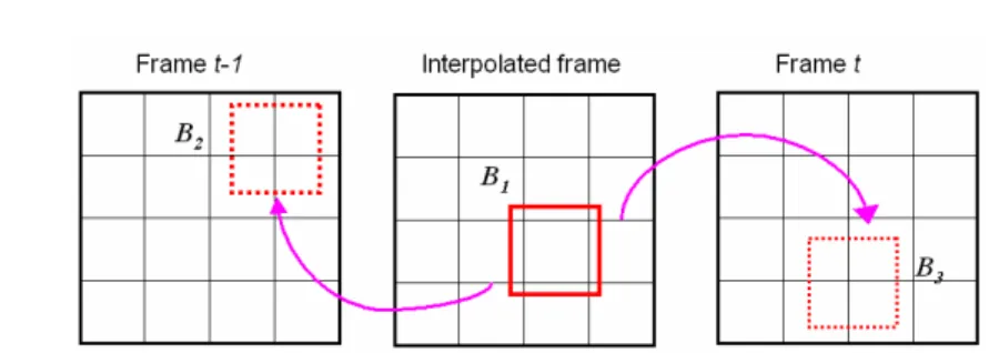
3.3 Overlapped Block Bi-directional Motion Estimation
More correct motion trajectory can be obtained when performing motion estimation with large blocks because the estimated motion vector may fall into a local minimum if the block is not large enough. To meet the requirement, overlapped block motion estimation is adopted. In addition, since we use bi-directional motion compensation, the more similarity between two directional predictors is, the more accuracy of the to-be-interpolated block can be derived. For this purpose, as shown in Fig. 4, deriving motion vectors from the to-be-interpolated block to the previous and current reference blocks for minimizing the difference between the bi-directional predictors is desired. The use of motion vectors pointing from the interpolated frame to the reference frame also releases the deficiencies of overlapped pixels and holes in the interpolated frames, which are unavoidable in conventional MCFI approaches [2-4]. Instead of applying bi-directional OBME directly, we first use uni-directional OBME to gener-ate an initial motion vector. In our observation, directly applying bi-directional OBME will possibly lead to an undesired motion vector since there is no known pixel value of the to-be-interpolated block as the ground truth. Without using the initial motion vector, a block in the plain areas may be found, which leads to a fairly small SAD between the two directional predictors, and therefore, an erroneous motion vec-tor is derived instead of the real object motion [12].
In our work, we use a general block matching algorithm (BMA) over a 12×12 enlarged block to get the initial motion vector for an 8×8 block by minimizing the following cost, first.
9 9 1 2 2 | (t c , c ) t ( c x , c y ) |, j i I x i y j I− x mv i y mv j =− =− + + − + + + +
∑ ∑
(3)where (mvx, mvy) represent the horizontal and vertical motion vector components,
It(x,y) is the luminance value in frame t at coordinates (x,y), and (xc, yc) is the top left point of the block to be estimated. In the refinement process, by minimizing the fol-lowing cost we can obtain a pair of motion vectors from the to-be-interpolated block to the previous and the current predictors, respectively.
9 9 1 2 2 2 2 2 2 | ( mvx , mvy ) ( mvx , mvy ) | t c rx c ry t c rx c rx j i I x mv i y mv j I− x mv i y mv j =− =− − − + − − + − + + + + + +
∑ ∑
(4)Fig. 4. Minimizing the difference between blocks B2 and B3 is the target of overlapped block
Until the current stage, we have derived the motion vectors to be (mvx/2+mvrx,
mvy/2+mvry) and (-mvx/2-mvrx, -mvy/2-mvry) from the to-be-interpolated block to the previous and the current reference blocks, respectively. Summarily speaking, the use of forward motion estimation first and followed by bi-directional motion estimation can not only successfully reduce the probability of finding an undesired motion vector but also get a smaller SAD between two directional predictors.
3.4 Motion Vector Smoothing
Once the bi-directional motion vectors are constructed, motion-compensated interpo-lation is performed to reconstruct the interpolated frames. Nevertheless, it is observed that some estimated motion vectors are so inconsistent with that of its neighbors that they will cause annoying artifacts and degrade video quality significantly. Most arti-facts originate from discontinuities in the motion fields, so a refinement by applying a median filter to do outlier-rejection and motion field smoothing is desired. By this process, we can identify those motion vectors which destroy the continuity of the motion fields.
Since we would like to remove an incoherent motion vector, the median motion vector among motion fields within a neighborhood will be viewed as the candidate motion vector. Besides, in our observation, majority voting should also be taken into consideration. If a certain motion vector dominates the motions in a 3×3 window of blocks, we also treat that motion vector as one candidate motion vector. For example, if there are four identical motion vectors within the 3×3 window, the motion really represents the motion trajectory in the region even though it is not the median one. 3.5 Adaptive Overlapped Block Motion Compensated Interpolation
When motion vectors of all blocks are well determined, interpolation is performed via using these motion vectors. A straightforward way to average two block-based bi-directional motion compensated predictors can be formulated as follows:
1 2
( ) ( ) ( ),
i f t f b t b
f x =w ×f x mv+ + ×w f x+mv (5)
where x denotes the location in the interpolated frame, and wf and wb are the weighs of forward and backward predictions in frames t1 and t2, respectively. The major draw-back of the straightforward block-based scheme is the occurrence of well-known blocking artifacts. It is often introduced when motion vectors are not correct or sig-nificantly uncorrelated with that of their corresponding neighboring blocks. OBMC provides an effective way to reduce blocking artifacts in video coding. It exploits motion vectors of adjacent blocks to reduce the undesired discontinuity. However, if all blocks carry out OBMC, the whole frame may become over-blurred [5]. An effec-tual criterion to decide whether the block motion across the block boundary should be involved in the OBMC process is essential. We calculate the difference between the motion vector of the current block and that of its four neighboring blocks. If the dif-ference is large, the boundary between two blocks is labeled as blockiness, and its neighboring block predictor overlapping the current block with 4×8 or 8×4 pixels will be considered, as indicated in Fig. 5(a). As a result, each pixel in an 8×8 block is combined using a weighted sum of at most three prediction values, which are ob-tained by using the motion vectors of the current block, the block at the left or right side and the block above or below the current block.
Figs. 5(b)–(d) give the weighting matrices for prediction generated by the mo-tions of the current block, the top or bottom block, and the left or right block of the current block. For the matrix of the current block, the weights decrease as the location is approaching to the block boundary, while for the other two, the change of weights is opposite. This type of weighting causes smooth transitions across block boundary and less pronounced block edge because the contribution of each block varies depend-ing on the pixel location within the block. In addition, if one or more block motions across the block boundary are decided not to be involved, their weights are added up to the matrix of the current block. For example, if the motion of the top block is not considered, the top half of the matrix in Fig. 5(c) will be merged into the weight of the current block. In the extreme, if all neighboring motions are not considered, OBMC is disabled for the current block.
Fig. 5. (a) Four neighboring blocks are taken into account and overlapped four pixels with the
current block. (b-d) Weighting matrices of the current, top and bottom, and left and right blocks, respectively.
4 Adaptive Frame Skip in the Encoder
Even though we have elaborated an effective MCFI algorithm, some interpolated frames are inevitable to have poor reconstructions. It is observed that the quality of interpolated frames relates to the information provided by the encoder; that is to say, the reconstructed quality is restricted by what is received at the decoder side. In order to enhance the quality of frame rate up-converted video sequences, in addition to improving the MCFI performance, it is essential to make an effort at the encoder side. An intuitive solution is to adaptively skip frames according to characteristics of object motions in a short instance, e.g., from the previous coded frame to the next coded frame. Instead of regular frame skipping, an adaptive frame skipping technique can achieve a more efficient compression ratio. In our observation, the activity of object movement varies along the time axis in most video sequences. When the frame activity is low or a unified motion is detected, the motion almost coincides with the predictable trajectory and those intermediate frames are easy to be generated well at the decoder. On the contrary, the motion trajectory changes dramatically when the frame activity is very high. As a result of this characteristic, if the entire sequence is encoded with a fixed frame skip, the power of MCFI is not totally exploited. The bits used for coding low activity frames are regarded as waste if these frames can be well interpolated by two frames at a far distance. At this time, a larger frame skip number
should be employed during the periods of low motion variation. Similarly, the fixed frame skip also results in poor performance for the video segment with high frame activity. In this case, a smaller frame skip number or even no skip will be better.
Fig. 6 reveals our implementation of the adaptive frame skip to determine which frames are encoded or skipped in the encoder. The MCFI module and quality
meas-urement of interpolated frames are embedded in the encoding process as flow control
units. We pre-define a maximum of frame skips between two coded frames. In each trial, starting from the largest frame skip number, we perform MCFI in the loop until a satisfactory frame skip number is found. In the flow-control feedback loop, a current reconstructed frame is sent to MCFI module together with a previous coded frame. Assuming that n frames are skipped, skipped frames are interpolated with motion compensation, and then evaluated by referencing the original frame. If the quality of interpolated frames is good enough, the current coded frame is taken and served as the previous frame in the next encoding. Otherwise, the current coded frame is regarded as useless, and re-encoding the immediately previous frame is employed. In other words, the module of quality measurement will give feedbacks to control the reading of the next encoding frame, the writing back of the current reconstructed frame and the permission of outputting encoding results. This iteration continues until all MCFI frames (i.e. interpolated frames) between the two coded frames are acceptable, and the worst case is that all frames should be encoded without any skip.
Fig. 6. Embed MCFI module and quality measurement of interpolated frames into the encoder
as flow control units. The dotted lines represent control signals to notify the next loaded frame and the current write-back frame.
An interpolated frame is regarded as poor when there is a bad region in this frame. As long as an annoying region exists, human beings will feel uncomfortable even if all other parts are with good quality. Therefore, we do not assess the overall frame quality but detect the existence of any poor region. However, it is not trivial to find a suitable criterion since videos are ultimately viewed by human beings, the only
"correct" method for quantifying visual quality is through subjective evaluation. Es-pecially for those interpolated frames, the purpose of generating them is to make users feel more comfortable as compared with viewing a reduced frame rate video se-quence. Precisely predicting the object location in the original missing frames is not the only criterion. Classical quality measurements, such as PSNR and mean squared error (MSE), may not represent accurate perceptual quality since they do not take the characteristics of human perception into account. Thus, the simple-computed PSNR is not a good evaluation metric to assess the performance of frame interpolation. On the other hand, subjective evaluation is usually too inconvenient, time-consuming and expensive. Therefore, we need an objective quality assessment to automatically pre-dict perceived video quality. Here, we adopt the structural similarity (SSIM) indexing approach proposed in [11], which works under the assumption that human visual perception is highly adaptive and sensitive to the extracted structural information in a scene rather than absolute signal difference. In this way, the feedback control in the encoder is well behaved according the quality assessment of interpolated frames, which makes FRUC work more efficient at the decoder side.
5 Experimental Results
To demonstrate the effectiveness of the proposed adaptive frame skip, we integrate FRUC into the H.264/AVC reference software, Joint Model version 9.0. We first exhibit the case where certain frames are interpolated with poor quality. Figs. 7(a) and 8(a) show that intervals (frame 54-64 and 148-156) of Mother&Daughter and inter-vals (frame 4-11 and 56-58) of Carphone sequences are with extremely awful quality, respectively. The poor performance results from large motions of several blocks in these frames, and these blocks are difficult to be reconstructed well by MCFI. It is inevitable to suffer from the poor results since the performance of MCFI is con-strained by the information provided by the encoder. We overcome the problem by applying adaptive frame skip during encoding process. In our experiments, the maxi-mal skipped number is set to 2. As shown in Fig. 7(b) and Fig. 8(b), the PSNR traces are both without abrupt drops as occurred in Figs. 7(a) and 8(a). In addition, the dot distributions in Figs. 7(b) and 8(b) represent the densities of encoded frames. It is obvious that the original poor frames are forced to be encoded to guarantee the overall quality of video reconstructions. We attribute the satisfactory performance to the success of adaptive frame skip.
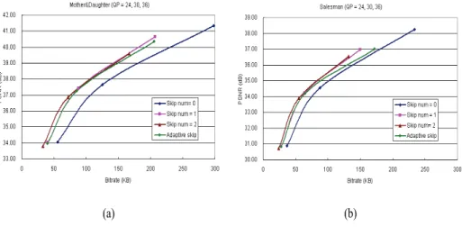
In addition, Fig. 9 shows the rate-distortion curves of the Mother&Daughter and the Salesman sequences. The four PSNR traces indicate the quality of full-frame-rate video reconstructions up-converted from 30-fps, 15-fps, 10-fps and adaptive frame rate coded bitstreams, respectively. The results demonstrate that: reconstructing frame-skipped videos by MCFI to achieve a full frame rate video communication is more effective than directly encoding videos with the full frame rate, especially for slow motion sequences. In this situation, lots of bitrate is saved while the video qual-ity degrades slightly. Generally speaking, the improvements are 2 dB and 1 dB for low-bitrate coding and high-bitrate coding, respectively. In spite of the effectiveness of the adaptive frame skip is slightly worse than that of the regular frame skip. Never-theless, the quality of each frame is ensured if the adaptive frame skip is adopted. Subjectively, this is an attractive merit in comparison with an abrupt quality drop in the regular frame skip mechanism.
31.5 32.5 33.5 34.5 35.5 0 20 40 60 80 100 120 140 F rame No. PS N R (a) 31.5 32.5 33.5 34.5 35.5 0 20 40 60 Frame No. 80 100 120 140 PSNR (b)
Fig. 7.PSNR traces of Salesman sequence: (a) regular frame skip = 2, (b) adaptive frame skip, and the occurrence of a dot means that the frame at that instance is coded. Dot distribution represents the density of encoded frames.
29 31 33 35 37 39 0 50 100 Frame No. 150 200 250 300 PSNR (a) 29 31 33 35 37 39 0 50 100 Frame No.150 200 250 300 PSN R (b)
Fig. 8.PSNR traces of Mother&Daughter sequence: (a) regular frame skip = 2, (b) adaptive frame skip, and the occurrence of a dot means that the frame at that instance is coded. Dot distribution represents the density of encoded frames.
Fig. 9.The rate-distortion curves of the (a) Mother&Daughter and (b) Salesman sequences for regular frame skip number = 0, 1, 2 and adaptive frame skip
6 Conclusions
This paper presents an adaptive frame skip mechanism to overcome the restriction that interpolation performance is intrinsically constrained by the information provided by the encoder. Attempting to embed the MCFI and quality measurement modules into the encoding loop is an effective means to ensure the interpolation performance. Once we embed our MCFI module into the encoder, interpolated frames can be gen-erated as if it is performed as a post-processing at the decoder side. Therefore, the quality of interpolated frames can be evaluated in advance, which is helpful to en-hance the performance of to-be-interpolated frames, either by rejecting some unfair motion descriptions or prohibiting some frames from being interpolated. Experimen-tal results show that the poor interpolated frames are forced to be encoded so that the overall video quality becomes much better. Besides our proposal, what the encoder can assist is to implicitly or explicitly transfer useful information to decoder for im-proving the reconstruction quality of interpolated frames.
References
1. S. C. Park, M. K. Park, and M. G. Kang, Super-resolution image reconstruction: a techni-cal overview, IEEE Signal Processing Magazine, vol. 20, pp. 21-36, May 2003.
2. Tien-ying Kuo and C.-CJ Kuo, “Motion-compensated interpolation for low-bit-rate video quality enhancement,” Proc. of SPIE Applications of Digital Image Processing XXI, vol. 3460, pp. 277-288, July 1998.
3. Bo-Won Jeon, Gun-Ill Lee, Sung-Hee Lee, and Rae-Hong Park, “Coarse-to-fine frame in-terpolation for frame rate up-conversion using pyramid structure,” IEEE Trans. on Con-sumer Electronics, vol.49, No. 3, pp. 499-508, Aug. 2003.
4. Tieyan Liu, Kwok-Tung Lo, Jian Feng and Xudong Zhang, “Frame interpolation scheme using inertia motion interpolation”, Proc. of Signal Processing:Image Communication, vol.18, pp221-229, March 2003.
5. Sung-Hee Lee, Ohjae Kwon, and Rae-Hong Park, “Weighted-adaptive motion-compensated frame rate-up conversion,” IEEE Trans. on Consumer Electronics, vol.49, No. 3, pp. 485-492, Aug. 2003.
6. Taehyeun Ha, Seongjoo Lee, and Jaeseok Kim, “Motion compensated frame interpolation by new block-based motion estimation algorithm,” IEEE Trans. on Consumer Electronics, vol.50, No. 2, pp. 752-759, May. 2004.
7. Yen-Kuang Chen, Anthony Vetro, Huifang Sun, and S. Y. Kung, “Frame-rate up-conversion using transmitted true motion vectors,” Multimedia Signal Processing, IEEE Second Workshop on, pp. 622-627, Dec. 1998.
8. Hisao Sasai, Satoshi Kondo, and Shinya Kadono, “Frame-rate up-conversion using reliable analysis of transmitted motion information,” Proc. of IEEE International Conference on Acoustics, Speech, & Signal Processing, May 2004.
9. Jiefu Zhai, Keman Yu, Jiang Li, and Shipeng Li, “A low complexity motion compensated frame interpolation method,” to be appeared in Proc. of IEEE International Symposium on Circuits and Systems, 2005.
10. Tien-yung Kuo, JongWon Kim, and C.-C. Jay Kuo, “Motion-compensated frame interpo-lation scheme for H.263 codec,“ IEEE International Symposium on Circuits and Systems, vol. 4, pp 491-494, May 1999.
11. Zhou Wang, Alan Conrad Bovik, Hamid Rahim Sheikh, and Eero P. Simoncelli, “Image quality assessment: from error visibility to structural similarity,” IEEE Trans. on Image Processing, vol.13, No. 4, pp. 600-612, Apr. 2004.
12. Ya-Ting Yang, Sung-Wen Wang, Yi-Shin Tung, Yi-Chin Huang, Ja-Ling Wu, “Low Bi-trate and Full Frame Rate Video Communication by Motion-Compensated Frame Interpo-lation,” to be appeared in EURASIP 2005