90 IEEE MICROWAVE AND WIRELESS COMPONENTS LETTERS, VOL. 16, NO. 2, FEBRUARY 2006
A Compact LTCC Branch-Line Coupler Using
Modified-T Equivalent-Circuit Model
for Transmission Line
Tsung-Nan Kuo, Yo-Shen Lin, Chi-Hsueh Wang, and Chun Hsiung Chen, Fellow, IEEE
Abstract—In this letter, a compact branch-line coupler is pro-posed by making good use of the three-dimensional layout capability of the low-temperature co-fired ceramic (LTCC) substrate. This branch-line coupler is accomplished by using lumped-inductors and lumped-capacitors to realize the modified-T equivalent-circuit model for the transmission line so that the circuit size may drasti-cally be reduced. Specifidrasti-cally, a very compact LTCC branch-line coupler with a size of 0.079 0.0717 is implemented and carefully examined, where is the wavelength of the multilayer structure at the operating frequency 0.
Index Terms—Branch-line coupler, low-temperature co-fired ce-ramic (LTCC).
I. INTRODUCTION
B
RANCH-LINE couplers are useful as power dividers or power combiners in various microwave circuits such as balanced amplifiers, balanced mixers, and phase shifters. Up to now, branch-line couplers were implemented using the microstrip [1], stripline [2], finite-ground coplanar waveguide (CPW) [3], and multilayer structures [4], however their sizes are relatively large due to the use of quarter-wavelength ( 4) transmission lines. Thus, the reduction of the size associated with these transmission lines is essential in decreasing the size of the branch-line coupler. Conventionally, there are two ways to reduce the size of transmission lines. The first one is achieved by using the folded line configuration [5], [6], but the resultant circuit area is still large. The other is accomplished by adopting lumped-element components such as metal-insulator-metal (MIM) capacitors [7]–[9], however, it needs precise lumped-element models based on careful measurements and leads to an inconvenient layout for tight integration.With the three-dimensional (3-D) layout capability, the LTCC has the greatest flexibility to implement numerous cou-pling mechanisms that would not be possible in planar circuits.
Manuscript received August 25, 2005; revised October 18, 2005. This work was supported by the National Science Council of Taiwan, R.O.C., under Grants NSC-94-2752-E-002-001-PAE, NSC-94-2213-E-002-055, and NSC-94-2213-E-008-042. The review of this letter was arranged by Associate Editor J.-G. Ma.
T.-N. Kuo, C.-H. Wang, and C. H. Chen are with the Department of Electrical Engineering and Graduate Institute of Communication Engi-neering, National Taiwan University, Taipei 106, Taiwan, R.O.C. (e-mail: chchen@ew.ee.ntu.edu.tw).
Y.-S. Lin is with the Department of Electrical Engineering, National Central University, Chungli 320, Taiwan, R.O.C.
Digital Object Identifier 10.1109/LMWC.2005.863194
Fig. 1. Circuit diagram of the conventional branch-line coupler.
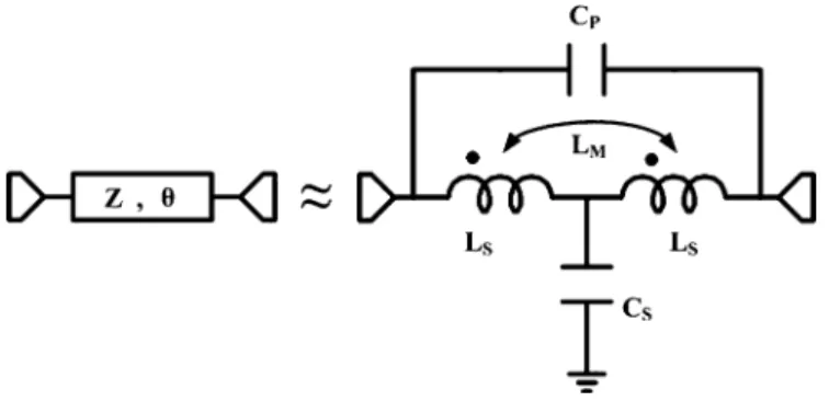
Fig. 2. Lumped-element modified-T equivalent-circuit model for a transmission line.
Basically, lumped-element realization of the transmission line in LTCC substrate, using the T or equivalent-circuit model [10], may be employed to reduce the circuit size, however these equivalent models are useful only in a narrow bandwidth around the center frequency. In order to expand the applicable frequency range of the equivalent circuit, this letter adopts the five-element modified-T model for the 4 lines [11], [12], so that a very compact LTCC branch-line coupler may be implemented.
II. COUPLERDESIGN ANDRESULTS
The structure of conventional branch-line coupler made of 4 transmission lines is shown in Fig. 1 where 35.36 , 50 , and 90 . For size reduction, the modified-T equivalent-circuit model [12] as shown in Fig. 2 is adopted to replace the 4 transmission lines in the coupler design. Ac-cording to the given characteristic impedance, electrical delay, and the operating frequency of 2.4 GHz, the required
1531-1309/$20.00 © 2006 IEEE
KUO et al.: COMPACT LTCC BRANCH-LINE COUPLER 91
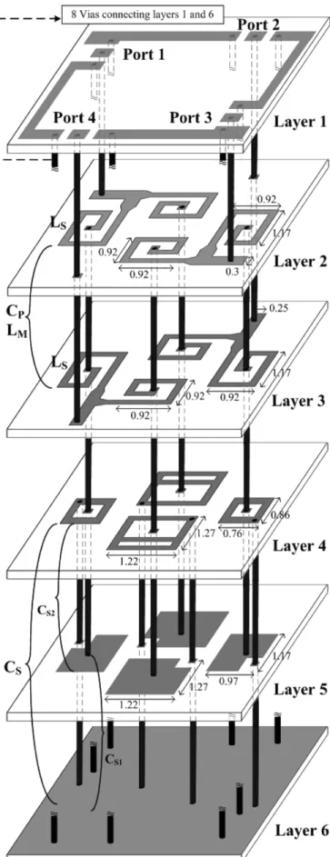
Fig. 3. Layout of the proposed LTCC branch-line coupler using lumped-element modified-T equivalent-circuit model for transmission line. The inductor width is 0.15 mm, the via radius is 0.5 mm, and all dimensions are in mm.
lumped-element values to realize the transmission line of char-acteristic impedance 35.36 (or 50 ) and
elec-Fig. 4. Measured and simulated scattering parameters of the proposed LTCC branch-line coupler.
trical length 90 may be obtained [12] for 35.36 90 1.29 nH 0.546 nH 2.95 pF 0.299 pF and for 50 90 1.83 nH 0.774 nH 2.08 pF 0.211 pF
Based on Fig. 2, a small size lumped-element modified-T equiv-alent-circuit model for the transmission line can be realized in the multilayered LTCC substrate. The multilayered LTCC sub-strate has a dielectric constant of 7.8, a loss tangent of 0.0015, and a layer thickness of 0.09 mm.
Shown in Fig. 3 is the circuit layout of proposed branch-line coupler in the LTCC substrate. Here, two modified-T equiva-lent-circuit models are used to replace the 35.36- 4 trans-mission lines between ports 1 and 2 and between ports 3 and
92 IEEE MICROWAVE AND WIRELESS COMPONENTS LETTERS, VOL. 16, NO. 2, FEBRUARY 2006
4, and similarly two modified-T equivalent-circuit models are employed to replace the 50- 4 transmission lines between ports 1 and 4 and between ports 2 and 3. Specifically, the in-ductors are realized by the spiral metal strips on layers 2 and 3, and the metal vias are used for interconnection among var-ious layers. The mutual inductors and the series capacitors are formed between the two inductors on layers 2 and 3. Note that the orientations of the two inductors are in the same direction such that the mutual inductances are positive. The mutual inductors and the series capacitors may be suit-ably modulated by changing the shapes of two inductors or ad-justing the distance between layers 2 and 3. The metal on layer 6 is the ground plane. So the parallel metal structures between layers 5 and 6 form one capacitor shunted to ground. Be-cause layer 4 is connected to layer 6 (the ground plane) by metal via, the metals between layer 4 and layer 5 also form the other capacitor shunted to ground. Thus, the shunt capacitor to ground is the sum of the two capacitors and . Due to the vertical arrangement of circuits, the resulting LTCC modi-fied-T equivalent-circuit model to replace the 4 transmission line may achieve a very compact branch-line coupler. Finally, by combining the modified-T equivalent-circuit models for the 50- and 35.36- transmission lines, one may accomplish the compact LTCC branch-line coupler as shown in Fig. 3.
The implemented branch-line coupler (Fig. 3) is measured by the microwave ground–signal–ground (GSG) probes and is simulated by the ADS momentum. By connecting the ports 1 and 3 (designed to locate at layer 2) and the ports 2 and 4 (designed at layer 3) to the layer 1 through the metal vias, the scattering parameters of this branch-line coupler may be measured by the GSG probes. The adjacent metals associated with each port are also attached to the ground by vias con-necting layers 1 and 6. Specifically, in measuring the scattering parameter such as between port 1 and port 2 by the GSG probes, the remaining two ports (port 3 and port 4) are termi-nated by the 50- loads. From the measured results, Fig. 4(a) and (b) show the return loss 15 dB in the frequency range of 2.147 2.47 GHz, over which the coupler exhibits a through loss of 4 5.1 dB and a coupling loss of 2.6 2.89 dB. The phase difference between and is shown in Fig. 4(c). Good agreement is observed between the measured and simulated results.
III. CONCLUSION
A new compact LTCC branch-line coupler has been presented based on the modified-T equivalent-circuit model for the trans-mission line. By taking advantages of vertical layout capacity of LTCC technology, the proposed branch-line coupler is ex-tremely small in size when compared with the conventional one. Specifically, the circuit area occupied by this LTCC branch line coupler is 4.216 mm 3.835 mm, which is only approximately 0.079 0.0717 . The proposed branch line coupler is also suit-able for MIC/MMIC applications.
REFERENCES
[1] M. Muraguchi, T. Yukitake, and Y. Naito, “Optimum design of 3-dB branch-line couplers using microstrip lines,” IEEE Trans. Microw.
Theory Tech., vol. 31, no. 8, pp. 674–678, Aug. 1983.
[2] G. P. Riblet, “A directional coupler with very flat coupling,” IEEE Trans.
Microw. Theory Tech., vol. 26, no. 2, pp. 70–74, Feb. 1978.
[3] C. T. Lin, C. L. Liao, and C. H. Chen, “Finite-ground coplanar-wave-guide branch-line couplers,” IEEE Trans. Microw. Wireless Compon.
Lett., vol. 11, no. 3, pp. 127–129, Mar. 2001.
[4] S. Banba, T. Hasegawa, and H. Ogawa, “Multilayer MMIC branch-line hybrid using thin dielectric layers,” IEEE Microw. Guided Wave Lett., vol. 1, no. 11, pp. 346–347, Nov. 1991.
[5] R. K. Settaluri, G. Sundberg, A. Weisshaar, and V. K. Tripathi, “Compact folded line rat-race hybrid couplers,” IEEE Trans. Microw. Theory Tech, vol. 10, no. 2, pp. 61–63, Feb. 2000.
[6] V. K. Tripathi, H. B. Lunden, and J. P. Starski, “Analysis and design of branch-line hybrids with coupled lines,” IEEE Trans. Microw. Theory
Tech, vol. 32, no. 4, pp. 427–432, Apr. 1984.
[7] M. Caulton, B. Hershenov, S. P. Knight, and R. E. Debrecht, “Status of lumped elements in microwave integrated circuit-present and future,”
IEEE Trans. Microw. Theory Tech, vol. 19, no. 7, pp. 588–599, Jul. 1971.
[8] T. Hirota, A. Minakawa, and M. Muraguchi, “Reduced-size branch-line and rat-race hybrids for uniplanar MMIC’s,” IEEE Trans. Microw.
Theory Tech, vol. 38, no. 3, pp. 270–275, Mar. 1990.
[9] R. K. Gupta and W. J. Getsinger, “Quasilumped-element 3- and 4-port networks for MIC and MMIC applications,” in IEEE MTT-S Int. Dig., 1984, pp. 409–411.
[10] S. Chaki, S. Aono, N. Andoh, Y. Sasaki, N. Tanino, and O. Ishihara, “Ex-perimental study on spiral inductors,” in IEEE MTT-S Int. Dig., 1995, pp. 753–756.
[11] Y. S. Lin, C. C. Liu, K. M. Li, and C. H. Chen, “Design of an LTCC tri-band transceiver module for GPRS mobile applications,” IEEE Trans.
Microw. Theory Tech, vol. 52, no. 12, pp. 2718–2724, Dec. 2004.
[12] T. S. Horng, J. M. Wu, L. Q. Yang, and S. T. Fang, “A novel modi-fied-T equivalent circuit for modeling LTCC embedded inductors with a large bandwidth,” IEEE Trans. Microw. Theory Tech, vol. 51, no. 12, pp. 2327–2333, Dec. 2003.