A Novel Angle Position Detector For Application to
Pattern
Recognition
Kang-Cheng Lin and Si-Chen Lee Department of Electrical Engineering
National Taiwan University Taipei, Taiwm Republic of China Tel:-886-2-363 525 1, Fax: -886-2-363 8247
Abstract
Simulating the function of biological retina using electronic hardware is the hture trend for intelligent electronics. It is believed that the first three features that a biological visual system extracts from an object image are edge position, edge orientation and angle position. The contrast edge position of an object and its orientation with respect to the horizontal line can be measured
from
the active hollow OUadrant Qrientation Detector' (FOQUOD). Based on this device, a double FOQUOD device which can extract the angle position is proposed for the first time and has been fabricated successfidly. The a-Si:H angle position detector is composed of two hollow FOQUODs packed in a concentric fashion and each FOQUOD consists of four a-Si:H p-i-n solar cells. The geometry of the top IT0 electrode of this detector is shown in Fig. 1, the outer (E,,, I,,, E,,, I,,) and inner (Ezx. I,, E,I&)
hollow FOQUODs are called F1 and F2, respectively. Each pair of pin diodes, i.e., E,, (EJ and I,,(Id,
E, (E& and I&(U,
are connected back-to-back, by tacking the ratio of the output photocurrent difference of these pairs of two photodiodes, i.e., (Ely-
Ily) / (El,-
IIJ,
(Ezy-Ia)
/ (E$-
Id7
the position and the orientation of a contrast edge can be extracted. When a contrast edge lies across the detector as shown in Fig. 2(a), the output signals (the short circuit currents) of F1 and F2 can be measured. Thus, two orientations 8, and of the contrast edge with respect to the horizonEd line are measured by F1 and F2, respectively, i. e., tanel = (Elv-
Ily) / (Elx-IIJ,
tan0, = (E,- I&) /(Ek-
U.
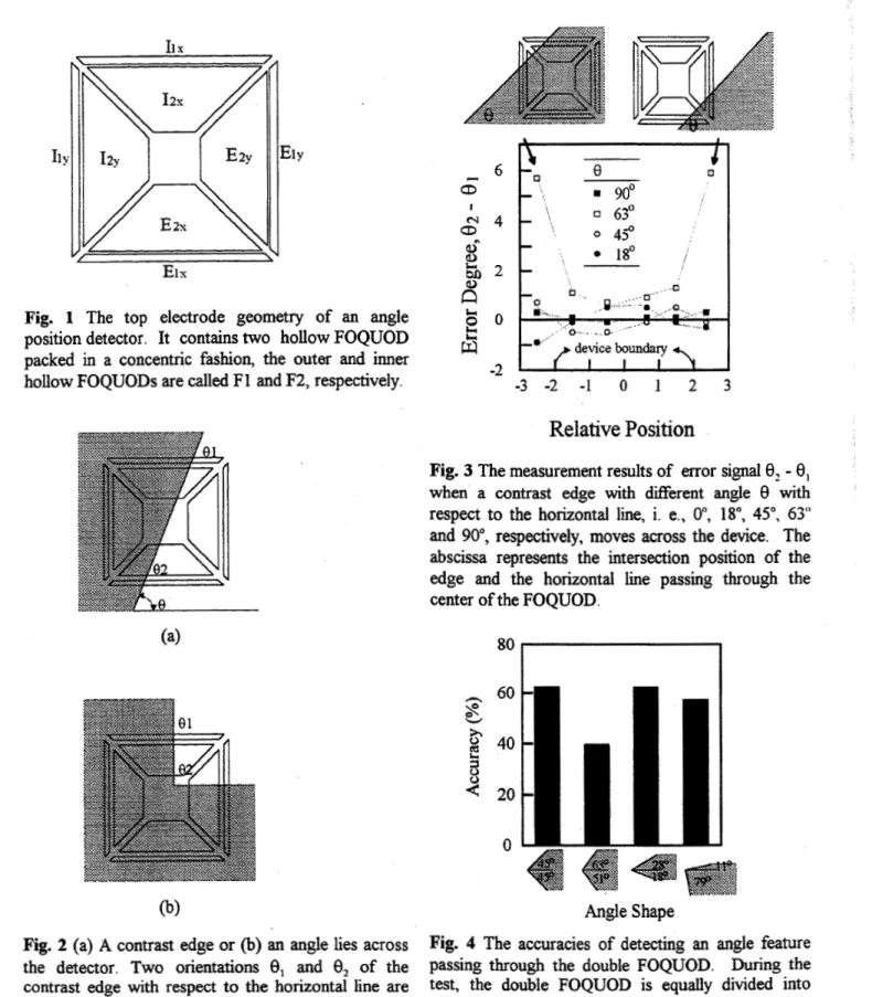
Conceptually, 0, is equal to €$ and it is considered as a contrast edge. But if an image with an angle passing through this device as shown in Fig 2(b), the measured orientations 6, and 0, are not equal and the image is considered as an angle. Therefore, the angle positions of an arbitrary image can then be extracted. Fig. 3 shows the measurement results of the error signal 0,-
0, when a contrast edges with different ansle with respect to the horizontal line through this device. There are five test samples whose edge orientations with respect to the horizontal line areo",
18", 45", 63" and go", respectively. The maximum difference value is 6 degree as shown in Fig. 3 when the contrast edge with a 63" orientation passing the boundary of this device. Therefore, a 6" error tolerance is given to set the boundary between the criterion of the "edge" and 'kngle". Fig. 4 shows the accuracies of detecting an angle feature passing through this device. During the test, the double FOQUOD is equally divided into sixteen squares, the tip of the test angle is moved sequentially to each of the center of the sixteen squares and measure the output current of the F1 and F2 cells. The angle is a combination of two contrast edges with angles CL andp
respect to the horizontal l i e . There are four test samples as shown in Fig. 4, a 90" angle with a =45" and
p
= -45" contrast edges (45"/-45"), a 114" angle (63"/-51"), a 46" angle (28"/-18") and a 9 0 angle (1 1"/-79"). If the threshold degree for distinguishing "edge" from "angle" is set to 6", the average accuracy by summing up 16 measurements are beyond 55%.eference
[ 11 K.
C.
Lin, W. J.Sah
andS
e.
Lee, "The Hydrogenated Amorphous Silicon Active Hollow Four Quadrant Orientation Detector For Application to Neural Network fmase Sensors," JEEE Trait on Electron Device, vol. 41, no. 5, p. 666, 1994.El s
Fig. 1 The top electrode geometry of an angle position detector. It contains
two
hollow FOQUOD packed in a concentric fashion, the outer and inner hollow FOQUODs are called F 1 and F2, respectively.(b)
Fig. 2 (a) A contrast edge or (b) an angle lies across the detector. Two orientations 8, and
8,
of the contrast edge with respect to the horizontal line are measured byF1
and F2, respectively. If 8, is approximately equal to8, within
6",the image is considered to bea
contrast edge; otherwise the image is considered to be an angle.-2
-
-3 -2 -I 0 1 2 3
Relative Position
Fig. 3 The measurement results
of
error signal-
8, when a contrast edge with different angle 8 with respect to the horizontal line, i. e., Oq 18", 4 5 O , 63" and go", respectively, moves across the device. The abscissa represents the intersection position of the edge and the horizontal line passing through the center of the FOQUOD.Angle Shape
Fig. 4 The accuracies