- Com~ulers & SIrucrum Vol. 59, No. 4. pp. 77 l-782, 1996 > Pergamon 00457949(95MO311-8 Prmted Copyright in Great 0 1996 El&r Britam. All tights reserved Science Ltd 0045-7949/96 ;I 5.00 + 0.00 . ,
MULTIOBJECTIVE
OPTIMIZATION
OF HARD DISK
SUSPENSION ASSEMBLIES:
PART II-INTEGRATED
STRUCTURE
AND CONTROL DESIGN
Yee-Pien Yang and Yi-An Chen
Department of Mechanical Engineering, National Taiwan University. Taipei, Taiwan 106, Republic of China
(Received 23 September 1994)
Abstract-The design of actively controlled hard disk suspension assemblies is formulated as a multi- objective optimization problem. The integrated structure/control objectives consist of natural frequencies and an optimal control performance index with weighted system state regulation errors and control efforts, subject to some side constraints on design variables that describe the geometry of the suspension. Two multiobjective optimization techniques, goal programming and compromise programming, are implemented through an interface program communicating with an advanced finite element analysis program. The feasibility of the optimal design is demonstrated and the final decision making is also discussed.
1. INTRODUCTION
The flying height of the slider over the rotating disk always dominates the record density, hence the size, weight and capacity of a hard disk drive. The fluctuation of the flying height is inevitable during the disk operation, stemming from disturbances such as vibrations of actuator arm, rotating flow induced vibrations, lateral positioning motion induced out-of- plane vibrations, inaccuracies of spindle alignment, and so on. Either passive design or active control on the suspension assembly can be used to reduce the suspension vibration, thereby keeping the flying height as small as possible. However, better structural designs usually facilitate the implementation of active vibration controls, which would have less effort than controlling a structure without optimal designs. Moreover, the inclusion of the control performance in the structural optimization must result in more feasible designs. This motivates many researchers devoting themselves to the integrated structure and control optimization technique, and this has received tremendous attention in recent years, due to the increasing demands on the reduction of structure weight and control effort, and on the improvement of closed-loop system response. Several approaches are being developed and used in the design and control optimization problems, and these can be broadly classified as: (1) sequential optimization; (2) simultaneous optimization; and (3) multiobjective optimization and other optimization techniques.
The sequential optimization technique carries out first the structural (or control) design followed sequentially by the control (or structural) design.
This process is repeated iteratively until the optimal solution is found to satisfy certain convergence criteria. One of the applications of this technique was addressed by Venkayya and Tischler [l]. The structural optimization was posed as the minimiz- ation of structural mass with the constraint on the fundamental frequency, and subsequently minimized was a quadratic performance function of the the energy of actuators and structural vibrations. The drawback of this approach is that the integrated solution depends on the sequential ordering of the control and structure design solutions.
The simultaneous optimization technique allows the designer to formulate a performance index, in structural parameters and control variables, as the sum of structural properties, such as mass or funda- mental frequency, and the quadratic performance index associated with a linear regulator optimal control problem. Recently, Grandhi [2] presented a simultaneous structure and control optimization of flexible structures. The structural weight or the Forbenious norm was minimized with constraints imposed on the closed-loop eigenvalues as well as damping parameters. Onoda and Watanabe [3] inte- grated the optimization of structure with the LQG controller, taking into account the suppression of the residual modes. The cost functional consisted of control effort and normalized structural mass, as well as weighting factors to guarantee a certain amount of modal damping ratios. Slater and McLaren [4] dealt with an integrated optimization of structure and control of flexible spacecrafts. Their design was to find structural parameters and control law to minimize a performance index that was system weight 771
772 Yee-Pien Yang and Yi-An Chen while satisfying control energy and displacement
constraints. Other examples of simultaneous optimiz- ation includes Bodden and Junkins [5], Hale et a/. [6],
Horta ef al. [7], Miller and Shin [8]. Lust and Schmit [9], Thomas et al. [lo], and so on. With this method, the sensitivity analysis may be of high order since the objective and constraint functionals must include both the control system and the structure with various design variables and weightings. Usually there exists no unique solution that would give the optimum for all objective functions simultaneously.
Various multiobjective optimization techniques have been proposed and applied in the industry, as surveyed by Tseng and Lu [l 11. For the application to the combined structure/control optimization, Rao
et al. [12] used the cooperative game theory for the
design of actively controlled structures subject to the constraints on damping parameters of the closed- loop system, formulating a multiobjective optimiz- ation problem. The structural weight and control energy were objective functionals for minimization with cross-sectional areas of members as design variables. Livine ef al. [13] formulated the synthesis of an actively controlled composite wing as a multi- disciplinary optimization problem, where a unique integration of analysis techniques spanning the diciplines of structures, aerodynamics, and controls is described. Gilbert and Schmidt [14] proposed a multilevel optimization approach to the integrated structure/control law design. The lower level con- sisted of independent structural design and control law design, and the design results and sensitivities were coordinated through the upper level optimiz- ation problem that reflected the desired objectives of the integrated structure/control law design.
With a sequential process in each optimization loop. Bruch et al. [15] proposed an alternative, namely. quasi-simultaneously multiobjective optimization approach to the simultaneous structural design and active control of a symmetric, cross-ply laminate. The problem was formulated as a multiobjective optimiz- ation problem with a two weighted sum of design and control objectives as performance indices, which consisted of common objectives on maximizing the fundamental frequency and minimizing dynamic responses, while one of which differs from the other with an additional objective on the minimization of either the closed-loop or open-loop control effort. Two performance indices were minimized simul- taneously. However, the performance index with the additional control effort was minimized with respect to control gains, while using the optimal structural design variables obtained by minimizing the other performance index with respect to the structural design variables.
The goal of Part II is to integrate structure and control optimization techniques on the shape design of suspension assemblies of hard disks. The design objective is to raise natural frequencies of the suspen- sion assembly so that it will not be excited easily by
undesirable disturbances. as stated in Part I. Simul- taneously, the state regulation errors and vibration control efforts are minimized with respect to structural parameters as well as control gains.
2. OPTIMAL CONTROL OF PARAMETRIC EQUATIONS
2.1. Modal analysis
In this section a generic class of optimization problem is defined specifically for vibration control of flexible structures. In terms of design variables x, the Nth-order equations of motion (1) that describe the dynamic behavior of suspension assembly can be transformed to principal (modal) coordinates
li’ + C’(x)rj + K’(.u)r~ = B’(x)u by the matrix transformation
(1)
q = Qi (S)$ (2)
where q is the modal coordinate vector. @(x) is the modal matrix whose columns are the corresponding normal modes, that is
@(-r) = [+I
3 429 1dJNl.
(3) For simplicity, the argument .X is omitted for subsequent analyses. The matrices K’, C’ and B’ have been normalized, so that we call the modal stiffness, modal damping, and modal input influence matrices, respectively, given byK’ = [ml-‘@rK@ = diag(w: wi.. co;) (4)
C’ = [m]-‘@rC@ = diag(2[,w,2[,~2.. .2[,w,) (5)
B’ = [ml-‘@ rB (6)
in which
[m] = @ ‘M@ = diag(m, mz . mN) (7)
is a diagonal modal mass matrix, ii and wi are the damping ratio and natural frequency of the ith normal mode.
2.2. Optimal control formulation
By the modal analysis the transformation to principal coordinates has uncoupled the equations of motion, leading to N separate single-degrees-of- freedom equations. In fact, high-frequency modes possess less kinetic and potential energy, and decay much faster than low-frequency modes due to the structural damping. It is efficient and practical for the designer to truncate those modal coordinates that correspond to high-frequency modes. In the follow- ing optimal control formulation, selected are S modal coordinates that describe the dominant dynamic be-
Multiobjective optimization of hard disk suspension assemblies-II 713 havior of the suspension assembly. In the state-space
form, eqn (1) is expressed by
y=Ay+Bu (8)
where y = [rl’ rj ‘]’ is the state variable vector, and A and B are the plant and input matrices given by
A=[_:,
_:,I
andB=[;,].
(9)
In order to design a linear quadratic regulator a performance index (PZ) can be defined as
m(4rQij+aTRa)dl, (10)
where ij = [q’qr]r, and Q and R are the state and control weighting matrices which have to be positive semi-definite and positive definite, respectively. Sup- pose that the system is either uniformly completely controllable or exponentially stable, the minimization of the performance index for a set of design variables yields the steady-state optimal control law
U* = -R-‘BTPy, (11)
where P is the Riccati matrix that satisfies the algebraic equation
A=P + PA - PBR-‘BrP + @;QCJ~= 0 (12)
in which Gd= diag(@ ~0). Therefore, the governing equation of the optimum closed-loop system can be written as
$=;iy, (13)
where
;i = A - BR-‘B=P. (14)
2.3. Dynamic responses
The above optimal control formulation can be used in two ways. First, the optimal control analysis is performed after the structure optimization is com- pleted; that is, the optimal shape of the suspension assembly is determined by minimizing the objective functions fi ,
fi
andf3
defined in eqns (2)-(4) of Part I, and then the control responses are examined. On the other words, the optimization will be carried out independently with dual sets of objective functions. Second, all the objective functions A, i = l-4 are considered simultaneously in the multiobjective optimization techniques: goal programing and com- promise programming, as stated in Appendix B of Part I. The second method will be elaborated in the next section.Disturbance responses. Since the major vibrations
of the suspension assembly are exerted by the disturb-
antes from either the air-bearing fluctuations or the rotating flow between disks, the disturbance force distribution depends on the preload of the suspension, Bying height, track location of the slider, rotation speed of the disk, and so on. The displacement response is investigated at the slider head with respect to disturbance force inputs at three different locations on the suspension assembly, as shown in Fig. 3 of Part I. The transfer functions between these disturb- ance inputs (forces) and the slider head output (displacement) are first computed by selecting the first six modes of the original suspension assembly, whose dimensions are listed in Appendix A of Part I.
Figure 1 shows the frequency responses of the slider head displacement with respect to the three input points of disturbances. It is apparent that the disturbance input point a, near the centroid of the suspension beam, produces the most oscillation on the slider head, while the disturbance input at point c on the slider only slightly excites the head because of the large stiffness of the air bearing. The phase delay due to the wave propagation from the disturb- ance input to the output point can be observed in the phase plot. Moreover, a small amount of change in the magnitude produces a much larger change in the phase of plot c than the other two phase plots. This is due to the noncolocation of input and output of a flexible structure, thereby resulting in a nonminimum phase transfer function.
Optimal control responses. For a better control
performance with less control effort, two input points are selected at a and b for simulation. It is true that the symmetric torsional modes are uncontrollable if the inputs act on the nodal lines of the suspension. However, the fundamental mode is usually a bending mode whose magnitude is much larger than that of high-frequency modes, and is a major part of vi- bration to suppress.
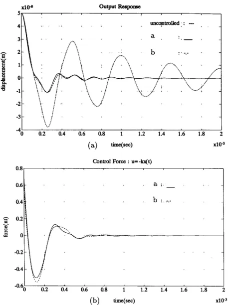
As the optimal control strategy is performed, the weighting matrices R and Q are chosen so that R = 1 and all elements of Q are zeros except Qkk = lO’j, the diagonal element corresponding to the output displacement point 0. By substituting the optimal control u* of eqn (11) into eqn (l), and calculating the closed-loop transfer functions for output point 0 with respect to input points a and b, we obtain their frequency responses as shown in Fig. 2. The input points a and b are, respectively, close to the maximum magnitudes of the first (bending) mode and the second bending (the fourth) mode. It is not surprising that the magnitudes of the first two bending modes (the first and fourth modes) are effectively reduced, in comparison with the frequency response of the uncontrolled system that the dashed curve describes. Moreover, time responses of the optimal control performance compared with the uncontrolled (open- loop) response are presented in Fig. 3, associated with its optimal control effort. Note that for the regulation control of the suspension the initial displacement of
114 Ye&km Yang and Yi-An Chen f i’
I.. i
. . e . a&lapMultiobjective optimization of hard disk suspension assemblies-II x10-B output Response 0.8 0.2 0.4 0.6 0.8 1 1.2 1.4 1.6 (a) time(=) Control Force : u= -kxft) 1.8 2 x10” 0.6 a:._ 0.4 . b :. _- zo.2 v e s -“.60 0.2 0.4 0.6 0.8 1 1.2 1.4 1.6 1.8 2 (b) tinxqsec) x10-3
Fig. 3. Open and closed-loop time responses of the original suspension without optimization: (a) displacement; (b) control force (control input at a: solid curve, b: dashdot curve, and uncontrolled
system: dashed curve).
the slider head is given as 0.05 pm, around 15 - 25% of the usual flying height 0.2 = 0.3 pm.
3. INTEGRATED OPTIMAL STRUCTURE AND CONTROL DESIGN
3.1. Multifunctional objectives
As in Part I, the shape of the suspension assembly is designed at its loaded status. Both objectives, to keep away from the excitation of disturbances and to actively suppress undesirable vibrations, motivate the designer to choose additional cost functionf, of eqn (10) along with the previous cost functions f, , fi and fs of eqns (2)-(4) of Part I, subject to the side constraints listed in Table 1 of Part I. The minimum and maximum values of f4 are calculated as 1.6943
x 10e4 and 7.6234 x 10W4, respectively.
775
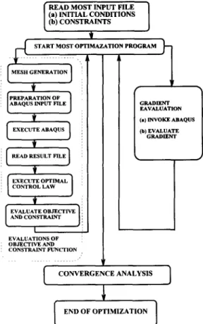
3.2. Computational$ow
As in Part I two multifunctional optimization techniques are investigated-goal programming and compromise programming. The major steps involved in the structure/control optimization are as follows:
(1) Read the MOST input file
All the input data are divided into three blocks, problem identification and initial parameters, design variable data, and multiobjective optimization methods and their parameters.
(2) Start the master program
Initially, the values of design variables are given, and the master program MOST will first evaluate the objective and constraint functions by invoking ABAQUS for structure analysis. Then the gradients of objectives and constraints are calculated for
176 Yee-Pien Yang and Yi-An Chen
searching a descent direction and a step size to obtain a new design point. In that way, MOST will branch into one of the three possible subroutines:
(2.1) Evaluation of objective and constraint functions
To proceed in this part, the finite element analysis must be performed. As ABAQUS is invoked, four steps are taken for structure analysis:
(a) Mesh generation-this is accomplished by a subroutine which generates coordinates of the struc- ture to be analyzed, subject to the change of design variables.
(b) Preparation of ABAQUS input file-a specific format of data input must be provided by the user for the problem to be solved by ABAQUS.
(c) Execution of ABAQUS-this step starts at the moment when a child process is forked. As the
structure analysis with ABAQUS is being executed in
the child process, the MOST program is sleeping until
the complete analysis succeeds within an assigned sleeping time.
(d) Read results file-the results file of ABAQUS saves variables in a specific format of binary or ascii code. The master program in MOST must identify and grasp what are required for subsequent analysis. e.g. natural frequencies and their corresponding modes.
(e) Evaluation of optimal control cost-a set of linear state-space equations of the structure control problem are formulated by choosing a finite number of effective modes according to the above analysis. Then the optimal control law, hence the optimal control cost, can be determined by Riccati equations.
The objective and constraint functions are then subsequently evaluated from the results of the structural analysis.
(2.2) Gradient evaluation
Two options for gradient evaluation are available in MOST:
(a) User-provided gradient-the user can program gradient expressions for the objective and constraint functions in separate subroutines. The gradient ex- pressions can also be verified by checking the gradient evaluation by the finite difference approach.
(b) Finite difference method-the forward, back- ward, or central finite difference method can be specified for calculating the gradients if users do not program the gradient expressions.
During the gradient evaluation with the finite difference approach, the optimizer will repeat the evaluation of the objective and constraint functions with perturbed design variables of specified variations by invoking ABAQUS repeatedly.
(2.3) Convergence analysis
Various convergence criteria of the optimization algorithm are specified in MOST:
ace-acceptable violation of constraints for feasible designs. For example, if acceptable tolerance for maximum constraint violation for feasible design is 0.01% then acu is set to 0.0001.
START MOST OF-TIM ‘,, A MESH GENERATION GRADIENT EA”AL”ATION (.) ITWOKE ABAQUS
I
I
END OF OPTIMIZATION IFig. 4. Computation flow of structure/control optimization.
acs-acceptable tolerance for the convergence parameter for optimum solution. The convergence parameter should be zero at the optimum. However, numerically, a value of acs between 0.001 and 0.0001 has worked fairly well.
Values of acu and acs control final convergence of
the optimization algorithm. Smaller values of these parameters will generally take more iterations to satisfy the convergence criteria.
The computational flow of the optimization, along with the structural analysis and the optimal control, is illustrated in Fig. 4.
3.3. Optimization results
For comparison with the results obtained in Part I, the same weightings of the two multifunctional optimization techniques are used. Both the indices /I and y are chosen as 1 and 2 for goal and compromise programmings, respectively. The optimization results are shown in Tables 1 and 2, and the optimal shapes in the finite element mesh for the cases of /3 = 1 and y = 1 are illustrated in Fig. 5.
(1) The goal programming technique yields a wider base yd of the suspension than the compromise
programming, while results in shorter mounting length of the suspension xd. Therefore, the shape designed by the compromise programming technique looks a little slender.
Multiobjective optimization of hard disk suspension assemblies-II
( >
a
Fig. 5. Optimal structure/control design results: (a) goal programming (j3 = 1); (b) compromise programming (y = 1).
778 Yee-Pien Yang and Yi-An Chen
Table 1. Structure/control optimization design results with goal programming /?=I 8=2 Design variable (mm) yb 6.8729 6.8509 xd 0.5000 0.5000 x2 0.1000 0.2890 wh 0.7922 0.8000 Objectives ; Lr 4.0117
2.9614 3.9364 x x x 10-d 1O-4 1O-4 3.9808 3.8969 2.9570 x x x 1O-4 1O-4 lO-4 1.9497 x 10-d 2.0562 x 1O-4 Errors d: 0.4172 x 1O-4 0.3863 x 1O-4 d: 1.3695 x 1O-4 1.3300 x 1o-4 d: 0.6946 x 1O-4 0.6902 x 10m4 d: 0.2554 x 1O-4 0.3619 x 1O-4 Frequencies (Hz) 01 2493 2512 0, 2540 2566 03 5917 5948
Table 2. Structure/control optimization design results with compromise programming (u = 1) y=l y=2 Design variable (mm) yb 6.0216 5.9600 xd 2.6373 2.8549 x2 0.1000 0.2835 wh 0.8000 0.8000 Objectives ; ; 3.4885 3.9303
3.8084 x x x 10m4 1O-4 10-d 3.4209 3.9934 3.9119 x x x lo-” 1o-4 10-h 2.0224 x 1O-4 2.0178 x 1O-4 Frequencies (Hz)
01 2626 2556
02 2867 2923
03 5411 5427
(2) All the flap heights in the optima1 design have a maximum allowable value 0.8 mm, except for the case fi = 1 of the goal programming to get a little smaller value 0.7922 mm. It is still hard to tell which case is better, the designer has to make a final decision with additional dynamical and manufacturing re- quirements on the suspension assembly.
(3) As in Part I, the final results in raising the natural frequencies are satisfactory. Without chang- ing the original length, thickness and tip width of the suspension beam, the first and second natural frequencies are raised over 400-500 Hz, and the difference between the second and the third natural frequencies increases at least 500 Hz.
(4) The final value of each objective function, as shown in Table 1 and 2, is larger than its minimum value and less than its maximum value. It is obvious that the nondominated solutions, or superior solu- tions, are not achieved, but a set of optimal solutions are obtained by making compromise between objective functions with each other.
4. DECISION MAKING
In the above analyses, we have more than one alternative of optimal designs. The decision maker needs to select the most desirable alternative, and his rational choice requires a criterion by which he evaluates different alternatives and places them in some form of ranking. Back to the original design objectives, the natural frequencies of the suspension assembly have to be raised so that it will not be excited easily by undesirable disturbances. A little different from Part I, we investigate the closed-loop frequency responses of the optimal suspension shape with optimal controls. The single input point is selected at a, and the output is chosen at 0 where the slider head displacement is measured, as shown in
~~~~~~~
3 4 5
~~~~I
I 10’ 10’ 105
frequencs(Hz)
Fig. 6. Closed-loop frequency responses of the suspension with integrated structure/control design (solid curve: compromise programming, dashdot curve: goal programming, dotted curve: original suspension
Multiobjective optimization of hard disk suspension assemblies-II 179
_ x10-s Output Response
-1’ I
0 0.2 0.4 0.6 0.8 1 1.2 1.4 1.6 1.8 2
‘ime&) x10-3
600 Contml force : u= Ax(t)
initial : . . .
compromise: _
goa1 : -.-
1
0.2 0.4 0.6 0.8 1 1.2 1.4 1.6 1.8 2
time(sec) x10-3
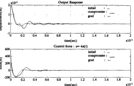
Fig. 7. Optimal control time responses of the suspension with integrated structure/control design (solid curve: compromise programming, dashdot curve: goal programming, dotted curve: original suspension
with optimal control).
Fig. 3 of Part I. That way the symmetrical torsional modes are uncontrollable but observable. This will not cause system instability because the torsional modes are seldom excited by out-of-plane disturb- ances that produce flying height fluctuations, and those high-frequency torsional modes will decay fast due to the structural damping.
Figure 6 shows the closed-loop frequency responses of the suspension designed by goal programming (/3 = 1) and compromise programming (y = 1), respectively, compared to the frequency response of the original suspension with an optimal control. It is interesting to find out that the low-frequency gain of the design with compromise programming is the smallest, while that with goal programming it is the largest. This indicates that low-frequency disturb- ances may bring about less fluctuation of the slider
head with the compromise programming design than the other two designs. Moreover, the frequency response with the compromise programing design has more attenuation for higher frequencies, and a little larger bandwidth than that of the goal programing design.
In the time responses as shown in Fig. 7 though, an alternative decision may be made for the final solution. For the goal programming design, the rise time may be a little larger due to a smaller bandwidth, however its smaller resonant peak in frequency relates a smaller peak overshoot in the time response and a larger phase margin to guarantee the stability [16]. In fact, the settling time of the initial displace- ment response of the suspension design with goal programming is much smaller than the other two cases. This must be very critical since the vibration of
-150 ___I____1 . ..I__ L.-l_ -155- -160- -165 - g -170- -175 - Bode Plot(magnitude) d&ign+control : _’ ‘- ‘~.~design/control : -.- ‘- -180 - -185 - -‘% 10’ 10’ 105 frequencfiHz)
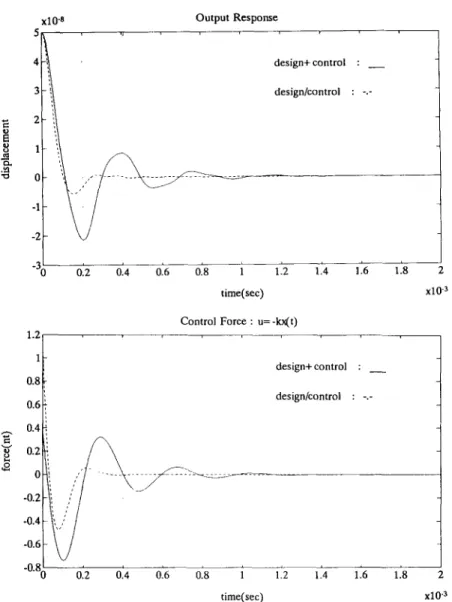
780 Yee-Pien Yang and Yi-An Chen Output Response design+control : _ design/control : -.- time(sec) Control Force : u= -kx(t) design+ control : - design/control : -.- I i._ I 1.2 1.4 1.6 1.8 2 time(sec)
Fig. 9. Time responses with goal programming design (j? = 1).
x10-J
frequencfiHz)
Multiobjective optimization of hard disk suspension assemblies-11 Control Force : u= h(t) 0.6 0.4- design+control : _ design/control : ,-.- . -0.8; 0.2 0.4 0.6 0.8 1 1.2 1.4 1.6 1.8 2 I time(sec) x10-3 Output Response 781 -20 L 0.2 0.4 0.6 0.8 1 1.2 1.4 1.6 1.8 2 I time(sec) x10”
Fig. 11. Time responses with compromise programing design (y = 1).
the slider has to be suppressed as soon as possible with moderate control effort. That way the goal programming design is the best desirable solution.
It is also necessary to convince people that the control performance of the suspension assembly de- signed with integrated structure/control optimization is superior to that without optimal control cost in the design as in Part I. Figure 8 is the frequency response of the suspension assembly with goal programming design. The solid curve (design + control) represents the case that the optimal control law is applied to the suspension designed with the objectives f, , f2 and f3, while the dashdot curve (design/control) describes the closed-loop system frequency response with integrated optimization of structure and control. Both frequency responses have almost the same peak value and bandwidth, that is, the same frequency of input at which the output is attenuated to a factor 0.707 times the input. This is verified in Fig. 9 where both time responses have a similar rise time. However, the
integrated structure/control design gives a much smaller resonant peak in frequency, which introduces more damping and leads to less settling time and less control effort in the regulation control. Similar results appear in the compromise programming design as shown in Figs 10 and 11.
5. SUMMARY AND CONCLUSIONS
The integrated structure/control multiobjective optimization of the suspension assembly of hard disk drives has been presented. In addition to the objective functions of natural frequencies, as depicted in Part I, also incorporated in the optimization is an optimal control performance index consisting of weighted system state regulation errors and control efforts. Two kinds of objectives have been achieved. First, the first and second natural frequencies are raised and the difference between the second and the third natural frequencies increases, so that the suspension is not
782 Yee-Pien Yang and Y&An Chen easily excited by undesirable disturbances. Second, as
a vibration controller is implemented it is required that the vibration be suppressed in minimal time and with least control effort. Both the goal programming and compromise programming techniques give feas- ible solutions, which would not be ideal, but the closest to the ideal ones in the sense that a best compromise is made among objectives. Furthermore, the fin4 decision making requires more investigation on the closed-loop frequency and time responses. For the design of actively controlled structures, the control performances with the integrated structure/ control optimization design are superior to those without the optimal control performance index in the design. The final solution may not be unique, but depends on additional engineering experience, manufacturing requirements, and so on.
Acknowledgmenr-This research was supported by National Science Council under Contract no. NSC 82-0401-E-002-380.
REFERENCES
1. V. B. Venkayya and V. A. Tischler, Frequency control and its effect on the dynamic response of flexible structures. AIAA J. 23, 1768-1774 (1985).
2. R. V. Grandhi, Structural and control optimization of space structures. Comput. Strucf. 31, 1399150 (1989). 3. J. Onoda and N. Watanabe, Integrated direct optimiz- ation of structure/regulator/observer for large flexible spacecraft. AIAA J. 28, 1677-1685 (1990).
4. G. L. Slater and M. D. McLaren, Disturbance model for control/structure optimization with full state feedback.
J. Guid. Cotnrol Dyn. 16. 5233533 (1993).
5. 6. 7. 8. 9. 10. 11. 12. 13. 14. 15. 16.
D. S. Bodden and J. L. Junkins, Eigenvalue optimization algorithms for structure/controller design iterations.
J. Guid. 8, 697-706 (1985).
A. L. Hale, R. J. Lisowski and W. E. Dahl. Optimal simultaneous structural and control design of maneuvering flexible spacecraft. J. Guid. 8, 86-93
(1985).
L. G. Horta, Jer-Nan Juang and J. L. Junkins, A sequential linear optimization approach for controller design. J. Guid. 9, 699-703 (1986).
D. F. Miller and J. Shim, Gradient-based combined structural and control optimization. J. Guid. 10, 291-298 (1987).
R. V. Lust and L. A. Schmit, Control-augmented structural synthesis. AIAA J. 26, 86-95 (1988).
H. L. Thomas, A. E. Sepulveda and L. A. Schmit, Improved approximations for control augmented structural synthesis. AIAA J. 30, 171-179 (1992). C. H. Tseng and T. W. Lu, Multiobjective optimization in mechanical and structural design. Model. Sci. Comput. (submitted).
S. S. Rao. V. B. Venkayya and N. S. Khot. Game theory approach for the integrated design of structures and controls. AIAA J. 26, 463-469 (1988).
E. Livne, L. A. Schmit and P. P. Friedmann, Towards integrated multidisciplinary synthesis of actively controlled fiber composite wings. J. Aircraft 27. 979-
992 (1990).
M. G. Gilbert and D. K. Schmidt, Integrated structure/ control law design by multilevel optimization. J. Guid. 14, 1001-1006 (1991).
J. C. Bruch. S. Adali, J. M. Sloss and I. S. Sader, Optimal design and control of cross-ply laminate for maximum frequency and minimum dynamic response.
Comput. Struct. 37, 87-94 (1990).
G. F. Franklin, J. D. Powell and A. Emami-Naeini.
Feedback Control of Dynamic Systems, 3rd edn. Addison-Wesley, Reading, MA (1994).