450 JOURNAL OF DISPLAY TECHNOLOGY, VOL. 10, NO. 6, JUNE 2014
A Holographic Projection System With an Electrically
Adjustable Optical Zoom and a Fixed Location of
Zeroth-Order Diffraction
Ming-Syuan Chen, Neil Collings, Hung-Chun Lin, and Yi-Hsin Lin
Abstract—An electrically tunable optical zooming holographic projection system with a fixed location of zeroth-order diffraction is demonstrated. By using two liquid lenses and an encoded Fresnel lens on a liquid crystal on silicon (LCoS) panel, the size of the pro-jected image of the holographic projection system is changeable; meanwhile, the locations of both of the zeroth-order diffraction and the first-order diffraction are unchanged. Therefore, the ze-roth-order diffraction can be removed by using a fixed optical high-pass filter. We can use it to realize an image size matching system for green light (532 nm) and red light (632.8 nm) without any po-sitional motion of the optical elements. The optical zoom function enhances the feasibility to realize a high-resolution full-color holo-graphic projection system.
Index Terms—Holographic projection, liquid lens.
I. INTRODUCTION
M
ICRODISPLAYS are commonly used in two types of projection systems, one is a conventional projection system based on amplitude modulations of microdisplays, the other is a holographic projection system based on phase or amplitude modulations of microdisplays to generate the diffraction patterns [1]–[3]. The advantages of holographic projections are high light efficiency and the feasibility of real 3D images [4]. Nevertheless, the different wavelengths of coherent light sources result in a mismatch of chromatic image sizes for full color applications [5]–[7]. To solve the mismatch of chromatic images, we proposed a holographic projection system adopting a liquid crystal lens to optically adjust the chromatic image sizes [8]. Makowski et al. proposed a method to divide the liquid crystal on silicon (LCoS) panel into three subzones for different computer generated holograms (CGH) [9]. However, many problems still need to be overcome, such as the slow response time of the liquid crystal lens ( 2 seconds), the reduction of the resolution of the image due toManuscript received October 29, 2013; revised December 26, 2013; accepted January 23, 2014. Date of publication January 28, 2014; date of current version May 05, 2014. This work was supported by the National Science Council (NSC) in Taiwan under Contract 101-2112-M-009-011-MY3. The work of N. Collings was supported by the EPSRC through Liquid Crystal Photonics Platform Grant EP/F00897X/1.
M.-S. Chen, H.-C. Lin, and Y.-H. Lin are with the Department of Photonics, National Chiao Tung University, Hsinchu 30010, Taiwan.
N. Collings is with the Engineering Department, Cambridge University, Cam-bridge CB3 0FA, U.K. (e-mail: [email protected]).
Color versions of one or more of the figures are available online at http:// ieeexplore.ieee.org.
Digital Object Identifier 10.1109/JDT.2014.2303132
subzones, and vignetting resulting from the small aperture size ( 2 mm). Moreover, the location of the projected image of the zeroth-order diffraction varies when we adjust the size of the projected image at different wavelengths. In order to eliminate the zeroth-order diffraction, we can mechanically adjust the location of an optical high pass filter and the system is then bulky for practical applications. In this paper, we demonstrate a holographic projection system using two liquid lenses which exhibits not only an electrically tunable optical zoom, but also a fixed location of projected image of zeroth-order diffraction. The aperture size of the liquid lens is large ( cm) and the switching time is fast ( 80 ms). We can eliminate the zeroth-order diffraction without mechanically changing the position of the optical high pass filter. In addition, the zoom ratio of the first-order diffraction is 1.98:1. The system we propose is more practical for full color holographic projec-tions based on the time-sequential projection approach, i.e., a single-panel solution. A single-panel solution allows a simpler optical system and a reduced cost compared with a three-panel solution. Moreover, our proposed system not only solves the mismatch of the chromatic image size, but also the positional shift of the zeroth-order diffraction.
II. STRUCTURE ANDOPERATINGPRINCIPLE
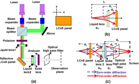
The holographic projection system with an electrically tun-able optical zoom consists of lasers, two beam expanders, a beam splitter, a polarizer, an analyzer, a mirror, reflective liquid crystal on silicon (LCoS) panel, one solid lens, two liquid lenses, an optical high-pass filter and a screen for observation, as shown in Fig. 1(a). The lasers we used were a He–Ne Laser (
nm) and a diode pumped solid state laser ( nm). The transmission axes of polarizer and analyzer are parallel to each other. The angle between the direction of linearly polar-ized light and the x-axis of LCoS panel is 45 degree.
The phase information created by the phase modulation of the LCoS panel includes a Fourier hologram and an encoded Fresnel lens. The function of “liquid lens 1” is to control the divergence of the laser beams impinging on the LCoS panel [equivalent to adjusting in Fig. 1(b)]. Two electrically tuning lenses: the Fresnel lens encoded on the LCoS panel and the “liquid lens 2”, are optical elements in charge of the function of optical zoom to adjust the image sizes at different wavelengths (chromatic image size). The “solid lens” is used to observe the Fourier transform of the hologram displayed on the LCoS panel, in the effective back focal plane of the “solid lens”. The high
1551-319X © 2014 IEEE. Personal use is permitted, but republication/redistribution requires IEEE permission. See http://www.ieee.org/publications_standards/publications/rights/index.html for more information.
Fig. 1. (a) Structure of the image matching holographic projection system. (b) Schematic illustration of the liquid lens 1 and LCoS panel in (a). (c) Schematic effective optical system of (a) with zeroth-order diffraction and first-order diffraction.
pass filter is a transparency with a black area to block the beam spot of zeroth-order diffraction.
Fig. 1(b) is the schematic effective optical system of the liquid lens 1 and LCoS panel in Fig. 1(a). is the distance between laser and LCoS panel, is the distance between the “liquid lens 1” and LCoS panel, and is the distance between the image plane of the “liquid lens 1” and LCoS panel. Assume the lens power of the “liquid lens 1” is . According to the thin lens formula, can be expressed as a function of :
(1) where is the wavelength. The effective optical system is de-picted in Fig. 1(c), where the light source is a spherical wave originating at a distance in front of the LCoS panel. can be controlled electrically by the “liquid lens 1”. The distance between the LCoS panel and “liquid lens 2” is is the dis-tance between the solid lens and the image of the zeroth-order diffraction, and is the distance between the solid lens and the image of the first-order diffraction. We place an optical high pass filter to filter out zeroth-order diffraction and a screen for observation of the image of the first-order diffraction. Assume , , and are the lens powers of the encoded Fresnel lens, “liquid lens 2”, and “solid lens”, respectively. The “liquid lens 2” and “solid lens” are attached together and the effective lens power of the combination then equals the summation of the two lens powers (i.e., ). The lens power of the encoded Fresnel lens does not affect the location of the ze-roth-order diffraction. According to the thin lens formula, can be expressed as
(2) where A is the electric current of the “liquid lens 2”. In (2), is a constant and is a function of and . Equation (2)
indicates that the image of zeroth-order diffraction changes with the lens powers of the “liquid lens 1”and the “liquid lens 2”. For practical applications, the image of the zeroth-order diffraction should be fixed (i.e., ); otherwise, the high pass filter has to be moved accordingly to filter out the zeroth-order diffraction. We actually can adjust and to fix the image location of the zeroth-order diffraction. and have to satisfy (3) which is derived by rearranging (2)
(3) Next, we use the Nazarathy and Shamir operator method to ana-lyze the first-order diffraction in a coherent optical system [10], [11]. The transform operator of the optical system can be ex-pressed as
(4) where and are the Fourier hologram and the lens power of the encoded Fresnel lens displayed on the LCoS panel, respectively. is the operator for the multiplication by a quadratic-phase exponential. is the operator for free-space propagation. The lens power of the encoded Fresnel lens is adjustable by setting the phase profile of the encoded Fresnel lens. According to the relations between the operators, (4) can be rewritten as
452 JOURNAL OF DISPLAY TECHNOLOGY, VOL. 10, NO. 6, JUNE 2014
In (5), the operator, , is the Fourier transform, and the operator, , is scaling by a constant. The first operator in (5) can be ignored since the phase modulation of the observed image is not observable on the camera. In order to obtain the Fraunhofer diffraction pattern, the second operator is then set to be unity, which means (6), shown at the bottom of the page. From (6), the image location of the first-order diffraction is related to , and . This also means we are able to fix the image location of first-order diffraction by adjusting . We assume that is a constant, . To fix both of the image locations of the zeroth-order diffraction and the first-zeroth-order diffraction, and have to follow the relation in (7) (shown at the bottom of the page) according to (2), (3), and (6). From (7) and (3), we can always find the corresponding and when changes. and (because is a function of ) are controllable by two liquid lenses. This also means we can adjust the focal length of the two liquid lenses in order to keep the image location of the zeroth-order diffraction and the first-zeroth-order diffraction constant.
Since we have fixed the image location of the zeroth-order diffraction and the first-order diffraction, the magnification can also be derived. After ignoring the first operator in (4) and setting the second operator to be unity, the transform operator T can be expressed as
(8) Then, the magnification of the output image M can be written as (9), shown at the bottom of the page. After putting
and into (9), M is
(10) From (10), we can see that the projected image size can be mag-nified by manipulating the lens power which depends on the applied electric current. As a result, the mismatch of chro-matic images can be adjusted electrically by liquid lenses. In addition, the corresponding and can be obtained from (3) and (7). is determined by which is electrically con-trollable from (1). Therefore, we can design the holographic projection system using two liquid lenses. The system exhibits not only an electrically tunable optical zoom, but also fixed image locations of the zeroth-order diffraction and first-order diffraction.
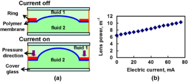
Fig. 2. (a) Working principle of liquid lenses. (b) Measured lens power as a function of the electrical current through a liquid lens. nm.
III. EXPERIMENTALRESULTS ANDDISCUSSIONS
To demonstrate the concept of a holographic projector with electrically tunable optical zoom, we adopt the reflective LCoS panel (LC-R 2500, HOLOEYE) and two liquid lenses: “liquid lens 1”(ML-20-35-VIS-LD, Optotune) with an aperture size of 20 mm and “liquid lens 2”(EL-10-30-VIS-LD, Optotune) with an aperture size of 10 mm. The resolution of the LCoS panel is 1024 768 with a pixel pitch of 19 m. The working princi-ples of the electrically tunable liquid lens (“liquid lens 2”) are shown in Fig. 2(a). The liquid lens consists of glass substrates, two optical fluids and a polymer membrane as a separator. The polymer membrane, a special selection of polymers, offers good optical and mechanical properties, such as high elasticity, a large elongation at break, low haze, are transmissive 90% from 240 to 2200 nm, non-absorbing (damage thresholds 25 kW/cm ), long-term stable and easy to process [12]. When an electric cur-rent is applied to the liquid lens, a piezoelectric ring transducer pushes the polymer membrane in the outer part of the lens and then the “fluid 2” is pumped to the center of the lens. The cur-vature of the polymer membrane is changed. As a result, the lens power of the liquid lens changes. When the liquid lens is used in the holographic projection system, the liquid lens does not need to change the position to affect the zooming properties of the system, only change the lens power at the same position. The measured lens power of the liquid lens as a function of elec-trical current is shown in Fig. 2. The measured lens power of the liquid lens (“liquid lens 2”) can be switched from 6.44 m to 10.27 m when the applied electrical current increases from 0 to 75 mA. The curvature of “liquid lens 1” is mechanically tunable. The measured lens power of the liquid lens (“liquid
(6)
(7)
Fig. 3. (a) as a function of when m . Red squares stand for experimental results and gray triangles stand for theoretical prediction. (b) as a function of when m. Blue dots stand for experimental results and gray triangles stand for theoretical prediction.
lens 2”) can be switched from 16.5 m to 20.2 m when we pressed the ring manually. Actually, the “liquid lens 1” can also use the electrically tunable one. The resolution of the liquid lens we measured is 15 lp/mm for modulation transfer function (MTF) 0.5. The response times of the liquid lens from 0 mA to 75 mA and 75 mA to 0 mA for light intensity at focus switched between 10% and 90% and between 90% and 10% are 35 ms and 78 ms. The slow response time may be because it takes time to change the volume of the liquid as we switch the piezo-electric transducer. The power consumption of the liquid lens is in a range between 30.4 mW and 92.4 mW when the driving voltage is switched from 0.76 V (current: 40 mA) to 1.32 V (cur-rent: 70 mA).
To measure as a function of , we then arranged the ex-perimental setup as shown in Fig. 1(a). In experiments, was 2.37 m, was 10 cm, was 20 cm, and the lens power of the solid lens was m . was set at 30 cm. A current of 40 mA was applied to “liquid lens 2” and then we adjusted the lens power of the “liquid lens 1” ( 0.56 m ) in order to make sure the light focused at cm after light passed through the solid lens. The lens power of the “liquid lens 1” was then set as 0.56 m . Then we increased the current of the “liquid lens 2” from 40 mA to 75 mA which meant the corresponding lens power of was increased from 3.35 m to 5.27 m . Then we measured the distance which is the distance between the solid lens and the focal spot of the zeroth-order diffraction. The measured results are shown in red squares in Fig. 3(a). In Fig. 3(a), decreases from 30 cm to 18.5 cm when increases from 3.35 m to 5.27 m . The gray triangles in Fig. 3(a) stand for the theoretical prediction based on (2) which agrees well with the experiments. As a result, when the lens power of “liquid lens 1” is fixed (i.e., is fixed), the image location of zeroth-order diffraction (i.e., ) changes with the lens power of “liquid lens 2”(i.e., ). That also means the high pass filter has to be moved around to block out the zeroth-order diffraction when the power of “liquid lens 2” is adjusted for changing the image size at different wavelengths. In order to keep a con-stant, the lens power of the “liquid lens 1”(i.e., ) should be adjusted when changes. To find out the relation between and , we put the screen 30 cm in the rear of the solid lens (i.e.,
cm) and observed the spot size on the screen. When the electric current of “liquid lens 2” was increased, we observed an enlarged laser spot on the screen. Therefore, we compensated this by adjusting the electric current of “liquid lens 1” in order to reduce the laser spot size and thereby maintain the min-imum laser spot size on the screen. We then recorded and the
Fig. 4. (a) as a function of . m . Red squares represent experimental results and gray triangles represent theoretical prediction. (b) as a function of . m. Blue dots squares represent experimental results and gray triangles represent theoretical prediction.
current from which can be calculated. as a function of is shown in Fig. 3(b) (blue dots) which agrees well the theoret-ical prediction of (1) (gray triangles). As a result, we can always find out a corresponding as changes in order to maintain the position of zeroth-order diffraction.
To measure the image location of first-order diffraction as a function of , we input a Fourier hologram with the resolution 384 384 pixels. From previous paragraph, was 0.56 m and cm. We placed the screen at 50 cm away from the solid lens. (i.e., cm) and we recorded images on the screen using a webcam (Logitech, PR9000). We then adjusted the lens power of the Fresnel lens and analyzed the corresponding images. When equals to m , the contrast ratio of the image is maximum. The value of was then fixed at m . We then increased by changing the current of the “liquid lens 2” and also changed according to Fig. 3(b) in order to keep cm. We moved the screen to record the images and recorded the distance between the screen and the solid lens when the contrast ratio of the image is maximal. as a function of is shown in Fig. 4(a). decreases from 50 cm to 36.9 cm when increases from 3.35 m to 5.27 m . The experimental results agree well with the theoretical prediction of (6). This indicates that when is unchanged, the image location of first-order diffraction
changes with the lens power of the “liquid lens 2” even though the image location of zeroth-order diffraction is unchanged.
Next, we measure as a function of when is fixed ( cm). Once again, we increased by changing the current of the “liquid lens 2” and also changed according to Fig. 3(b) in order to keep cm. We then changed and recorded the images on a screen using a webcam. When the contrast ratio of the image is maximal, we recorded the value of . as a function of is shown in Fig. 4(b). decreases from m to m when increases from 3.35 m to 5.27 m . The experimental results agree well with the theoretical prediction of (7). As a result, when we adjust the lens power of the Fresnel lens , we can always find a corre-sponding lens power by adjusting the current of the “liquid lens 2” in order to keep both image locations of zeroth-order diffraction and first-order diffraction ( and ) unchanged.
To measure the magnification, we input a Fourier hologram with the resolution 384 384 pixels and projected at the screen 50 cm in the rear of the solid lens. In the experiments, the dis-tances of and in Fig. 1(c) were set at 20 cm, 30 cm, and 50 cm, respectively. We did similar experiments to change
454 JOURNAL OF DISPLAY TECHNOLOGY, VOL. 10, NO. 6, JUNE 2014
Fig. 5. The magnification as a function of . Blue squares stand for the ex-perimental results and gray triangles stand for theoretical prediction.
, and as changes in order to obtain fixed image loca-tions of the zeroth-order diffraction and the first-order diffrac-tion ( cm and cm). A webcam was used to take photos of the screen and calculate the magnification by comparing the sizes of images. For calibration, the image when m (i.e., mA), m
m was set as . Fig. 5 shows the magni-fication as a function of (blue squares). The magnification decreases from 1.98 to 1 when increases from 3.35 m to 5.27 m increases from m to 0.56 m , and increases from m to m . The theoretical pre-diction (gray triangles) is similar to the experimental results. The zoom ratio is 1.98:1 in Fig. 5. Therefore, by adjusting the lens powers of “liquid lens 1”, “liquid lens 2” and the encoded Fresnel lens, we can change the size of the projected image while maintaining the image locations of zeroth-order diffrac-tion and the first-order diffracdiffrac-tion.
To compare the images with and without the zeroth-order diffraction, we captured the images on the screen without and with the optical high pass filter, as shown in Figs. 6(a) and (b). The parameters of the experimental setup are: m, cm, cm, cm, cm, a cur-rent of 40 mA for “liquid lens 2”, m
m , and m . Without the high pass filter, the ze-roth-order diffraction seriously affects the image on the screen, as shown in Fig. 6(a). Using a high pass filter to block the zeroth-order diffraction is necessary for a holographic projec-tion system, as shown in Fig. 6(b). In Fig. 6(c), the image is smaller when the wavelength decreases compared to Fig. 6(b). The image size of Fig. 6(b) is 1.20 larger than that of Fig. 6(c). According to (10), the ratio of two wavelengths is
which is close to 1.20:1. We adjust the lens powers: m m m and the size of the red image in Fig. 6(b) can be reduced to the size of the green image in Fig. 6(c), as shown in Fig. 6(d). Since the location of the zeroth-order diffraction and first-order diffrac-tion are fixed, we can adjust the image size at different wave-lengths without changing the high pass filter and the observation plane (screen). Besides, the liquid lenses we used are affected by gravity. Gravity results in an asymmetrical parabolic phase pro-file of the liquid lens which produces aberration. As a result, the image of the first-order diffraction is distorted and this affects the image quality of the projected image. However, the aber-ration of the liquid lens can be compensated by adjusting the hologram on the LCoS device. The image quality can also be improved by improving the liquid lenses or liquid crystal lenses
Fig. 6. Projected images of “LC”: (a) without a high pass filter ( nm, the current of the “liquid lens 2” 40 mA); (b) with a high pass filter ( nm, the current of the “liquid lens 2” mA), and (c)with a high pass filter
nm, the current of the “liquid lens 2” mA). In (a), (b), (c),
m m m . (d) The projected image with
a high pass filter ( nm, the current of the “liquid lens 2” mA,
m m m ).
Fig. 7. Projected images of “ ” with a high pass filter. (a) The current of the
“liquid lens 2” mA, m m
m . and (b) the current of the “liquid lens 2” mA, m m m , and (c) the current of the “liquid
lens 2” mA, m m m .
nm.
[13]–[15]. The image quality of tunable focusing liquid lenses has been reported [16]–[19]. In order to achieve a fast refresh rate, the response time of the liquid lenses should be faster. A tunable focusing lens using blue phase liquid crystals can be fast ms [20]. This should be fast enough for the color-sequential approach.
The image size can also be changed by changing the lens power of the liquid lens. In Fig. 7, we projected a lattice pat-tern and changed the current of “liquid lens 2”. The image size reduces when increases, decreases and decreases. Therefore, the image size of the first-order diffraction is tunable by adjusting the lens powers of the liquid lenses while keeping the zeroth-order diffraction blocked.
IV. CONCLUSION
We have demonstrated an electrically tunable optical zooming holographic projection system with a fixed location of zeroth-order diffraction. By adding two liquid lenses in a holographic projection system, we can fix the locations of both of the zeroth-order and the first-order diffraction and change the size of the projected image at the same time. Therefore, we can remove the zeroth-order diffraction by using a fixed optical high-pass filter. The zoom ratio of our system is
which is large enough to compensate the mismatched image size in the visible range (i.e., 700:400 or 1.75:1). When the image quality of the liquid lens is good enough, the focusing spot of zeroth-order diffraction is small and we can block this spot by using a small spatial filter. In this way, we can filter away the zeroth-order diffraction without affecting first-order diffraction. The best way to improve the image quality is to improve the performance of the liquid lens. We demonstrate the concept using two wavelengths in this paper. The required optical zoom ratio is 1.75:1 in visible range (400–700 nm), but the optical zoom ratio in the experiments can be up to 1.98:1 for red light. As a result, our design can be used to realize full color projected imaging. The optical zoom function enhances the
feasibility to realize a high resolution, three color, holographic projection system.
ACKNOWLEDGMENT
The authors would like to thank Prof. S.-H. Lin (NCTU), Dr. C.-H. Lin (NCTU), and E. Liao and S. Hong (Jasper Display Corporation) for technical assistance and support.
REFERENCES
[1] A. Georgiou, J. Christmas, J. Moore, A. J. Chapman, A. Davey, N. Collings, and W. A. Crossland, “Liquid crystal over silicon device characteristics for holographic projection of high-definition television images,” Appl. Opt., vol. 47, pp. 4793–4803, 2008.
[2] E. Buckley, “Holographic laser projection,” J. Display Technol., vol. 7, no. 3, pp. 135–140, Mar. 2011.
[3] E. Buckley, “(2010). Holographic projector using one lens,” Opt. Lett., vol. 35, pp. 3399–3401, 2010.
[4] D. Teng, L. Liu, Z. Wang, B. Sun, and B. Wang, “All-around holo-graphic three-dimensional light field display,” Opt. Commun., vol. 285, pp. 4235–4240, 2012.
[5] M. Makowski, I. Ducin, K. Kakarenko, A. Kolodziejczyk, A. Siemion, J. Suszek, M. Sypek, and D. Wojnowski, “Efficient image projection by Fourier electroholography,” Opt. Lett., vol. 36, pp. 3018–3020, 2011. [6] M. Makowski, M. Sypek, I. Ducin, A. Fajst, A. Siemion, J. Suszek, and
A. Kolodziejczyk, “Experimental evaluation of a full-color compact lensless holographic display,” Opt. Express, vol. 17, pp. 20840–20846, 2009.
[7] B. Marx, “Holographic optics-miniature laser projector could open new markets,” Laser Focus World, vol. 42, p. 40, 2006.
[8] H. C. Lin, N. Collings, M. S. Chen, and Y. H. Lin, “A holographic pro-jection system with an electrically tuning and continuously adjustable optical zoom,” Opt. Exp., vol. 20, pp. 27222–27229, 2012.
[9] M. Makowski, I. Ducin, K. Kakarenko, J. Suszek, M. Sypek, and A. Kolodziejczyk, “Simple holographic projection in color,” Opt. Express, vol. 20, pp. 25130–25136, 2012.
[10] M. Nazarathy and J. Shamir, “Fourier optics described by operator al-gebra.,” J. Opt. Soc. Amer., vol. 70, pp. 150–159, 1980.
[11] J. W. Goodman, Introduction to Fourier Optics, 2nd ed. New York, NY, USA: McGraw-Hill, 1996.
[12] M. Blum, M. Büeler, C. Grätzel, and M. Aschwanden, “Compact op-tical design solutions using focus tunable lenses.,” in Proc. SPIE, 2011, vol. 8167, p. 81670W.
[13] S. Xu, H. Ren, and S. T. Wu, “Dielectrophoretically tunable optofluidic devices,” J. Phys. D: Appl. Phys., vol. 46, p. 483001, 2013. [14] L. Ren, S. Park, H. Ren, and I. Yoo, “Adaptive liquid lens by changing
aperture,” J. Microelectromech. Syst., vol. 21, p. 953, 2012. [15] H. Ren and S. T. Wu, Introduction to Adaptive Lenses, 1st
ed. Hoboken, NJ, USA: Wiley, 2012.
[16] H. C. Lin and Y. H. Lin, “An electrically tunable focusing pico-pro-jector adopting a liquid crystal lens,” Jpn. J. Appl. Phys., vol. 49, 2010, Art. ID 102502.
[17] J. Y. Yiu, R. Batchko, S. Robinson, and A. Szilagyi, “A fluidic lens with reduced optical aberration,” in Proc. SPIE, 2012, vol. 8301, p. 830117.
[18] J. H. Sun, B. R. Hsueh, Y. C. Fan, J. MacDonald, and C. C. Hu, “Optical design and multiobjective optimization of miniature zoom optics with liquid lens element,” Appl. Opt., vol. 48, pp. 1741–1757, 2009. [19] S. Murali, P. Meemon, K. S. Lee, W. P. Kuhn, K. P. Thompson, and J.
P. Rolland, “Assessment of a liquid lens enabled in vivo optical coher-ence microscope,” Appl. Opt., vol. 49, pp. D145–D156, 2010. [20] Y. H. Lin, H. S. Chen, H. C. Lin, Y. S. Tsou, H. K. Hsu, and W. Y.
Li, “Polarizer-free and fast response microlens arrays using polymer-stabilized blue phase liquid crystals,” Appl. Phys. Lett., vol. 96, Art. ID 113505.
Ming-Syuan Chen received the B.S. degree in
electrical engineering and computer science form National Chiao Tung University, Hsinchu, Taiwan, in 2010, and is currently working toward the Ph.D. degree at Department of Photonics, National Chiao University, Hsinchu, Taiwan.
His current research interests include the develop-ment of phase modulators, liquid crystal lenses and the designs of electrically tunable optical zoom sys-tems based on liquid crystal lenses.
Neil Collings was born in Stalybridge, Cheshire
in 1949. He was educated at Manchester Grammar School, and received the B.A.(Hons.) degree in natural sciences from Trinity Hall, Cambridge University, Cambridge, U.K., in 1971, and the Ph.D. degree in physics from the University of Salford in 1977.
At the beginning of his career, he worked in birefringence studies and optical sensors. He began studying liquid crystal spatial light modulators and their application to optical correlators during his work at the Standard Telecommunications Laboratories between 1984 and 1989. He wrote a book entitled “Optical Pattern Recognition Using
Holo-graphic Techniques” (Addison-Wesley, 1988), based on his research during
this period. He continued working in the field of liquid crystal devices and their associated optical systems until he moved to the University of Cambridge in 1999. He is currently a Reader in Liquid Crystal Photonics in the Photonics & Sensors group of the Department of Engineering.
Dr. Collings is a Fellow of the Institute of Physics and a Senior Member of SPIE.
Hung-Chun Lin received the B.S. degree in
electrical engineering from National Sun Tat-Sen University (Taiwan), in 2005, the M.S. degree from the Display Institute, National Chiao Tung University (Taiwan), in 2007, and the Ph.D. degree from the Department of Photonics, National Chiao Tung University (Taiwan), in 2012.
His research interests include the liquid crystal and polymer composite film, liquid crystal lenses and the designs of electrically tunable optical systems based on liquid crystal lenses.
Yi-Hsin Lin received the B.S. degree in physics
from National Tsing Hua University (Taiwan), in 1998, the M.S. degree from the Institute of Electro-Optical Engineering, National Chiao Tung University (NCTU, Taiwan), in 2000, and the Ph.D. degree in optics from the College of Optics and Photonics: CREOL & FPCE, University of Central Florida, Orlando, FL, USA, in 2006.
She is currently an associate professor in the De-partment of Photonics of NCTU (Taiwan). Several papers were selected as cover pages or feature arti-cles in Physical Review Letters and Optics Express. The research interests of Prof. Lin are in physics of liquid crystals (LC), LC-based optical devices, and bio-sensing based on a liquid crystal/polymer system.
Prof. Lin is a recipient of Glenn H. Brown Prize awarded by International Liquid Crystal Society (ILCS) in 2008, the 2006 OSA New Focus/Bookham award, 2005 Newport Research Excellence award, and several other awards.