This content has been downloaded from IOPscience. Please scroll down to see the full text.
Download details:
IP Address: 140.113.38.11
This content was downloaded on 26/04/2014 at 08:17
Please note that terms and conditions apply.
Light extraction enhancement of InGaN-based green LEDs with a composite omnidirectional
reflector
View the table of contents for this issue, or go to the journal homepage for more 2006 Semicond. Sci. Technol. 21 1513
(http://iopscience.iop.org/0268-1242/21/12/001)
Semicond. Sci. Technol. 21 (2006) 1513–1517 doi:10.1088/0268-1242/21/12/001
Light extraction enhancement of
InGaN-based green LEDs with a
composite omnidirectional reflector
C H Lin
1,2, H C Kuo
1, C F Lai
1, H W Huang
1, K M Leung
3,
C C Yu
1,2and J R Lo
21Institute of Electro-Optical Engineering, National Chiao Tung University, Hsinchu 300,
Taiwan, Republic of China
2HighLink Technology Corporation, ChuNan 350, Taiwan, Republic of China
3Department of Computer and Information Science, Polytechnic University, Six Metrotech
Center, Brooklyn, NY 11201, USA E-mail:[email protected]
Received 13 July 2006, in final form 17 August 2006 Published 25 September 2006
Online atstacks.iop.org/SST/21/1513
Abstract
We have designed, fabricated and measured the electroluminescence of InGaN-based green light-emitting diodes (LEDs) having composite omni-directional reflectors (ODRs) deposited on their backside. The composite ODR is composed of a stack of two individual ODRs, each of which is made of alternating layers of TiO2and SiO2with a thickness ratio
that gives the largest possible 1D photonic bandgap. The lattice constants of these individual ODRs are chosen so that the effective bandgap of the resulting ODR completely covers the emission spectrum of the LEDs. The effective bandgap of our ODR extends from 498 nm to 548 nm. At a driving current of 300 mA, and with the LED emission peak at about 525 nm and a FWHM of about 35 nm, the light output powers of the LED with the composite ODR and the LED with a conventional Ti/Al metal reflector are found to be 52.9 mW and 40.7 mW, respectively. This 30% light extraction enhancement can be attributed to our composite ODR which has a higher reflectance, a lower optical absorption and a wider reflection angle compared with the Ti/Al reflector.
(Some figures in this article are in colour only in the electronic version)
1. Introduction
Enhancements in the efficiency and the reliability of light-emitting diodes (LEDs) of different colours, as well as the reduction in their manufacturing costs, continue to be exciting areas of research and development. The demand for white LEDs in particular continues to accelerate, as their applications in a multitude of consumer electronics, including televisions and many hand-held devices, and in various indoor and outdoor lightings, proliferate.
There are currently several ways of producing white LEDs [1,2], including mixing the light generated by red (R), green (G) and blue (B) LEDs, the use of blue or UV LEDs with a layer of yellow phosphor grains and the use of quantum dots
[3–6]. Each method has its own advantages and disadvantages [7–15]. In the case of the RGB solution, the potential to generate white light with a wider colour gamut, especially for LCD back-lighting applications, is rather promising. However, the main challenge remains to be the performance of the green LEDs because the inherent lower efficiency of InGaN-based green LEDs compared with those of the corresponding red and blue LEDs.
An important way to improve the performance of LEDs is to enhance their light extraction efficiency using mirrors to reflect light within the device upwards, towards the top. Metallic mirrors, DBRs and omnidirectional reflectors (ODRs) have been used for this purpose. The advantages of ODRs over the other alternatives have been fully demonstrated and will
C H Lin et al
not be elaborated here [16]. They are made with optically transparent dielectric materials with alternating layers of high and low refractive indices. Typically, pairs of TiO2and SiO2
are used because of their excellent optical and mechanical properties. The relative thicknesses of the layers are optimized to have the largest possible fractional bandgap for their given refractive indices. The lattice constant is then chosen so that this bandgap lies in the middle of the emission spectrum of the LED.
The relatively poorer performance of the InGaN-based green LEDs compared with their red and blue counterparts is due primarily to the poorer performance of the quantum efficiency and epitaxial quality. These problems, in turn, stem from the significantly larger relative width of the emission spectrum of the green LEDs. For example, our blue LEDs at 455 nm have a FWHM of 20 nm. This amounts to a fractional width of 4.4%. On the other hand, our green LEDs at 525 nm have a FWHM of 35 nm, and therefore have a fractional width of 6.6%. Thus the green LEDs have an emission spectrum that is 50% wider than that of the blue LEDs. Therefore although an ODR with a complete 1D photonic bandgap that covers the entire emission spectrum can be achieved for the blue LEDs using pairs of TiO2 and SiO2 with appropriate
thicknesses, similar optimization for the green LEDs gives the best complete 1D photonic bandgap that covers only 80% of the emission spectrum.
Our solution here is to use a composite ODR made by stacking two individual ODRs on the backside of the LED. Each of the individual ODR has a thickness ratio for the TiO2
and SiO2that gives the largest possible 1D photonic bandgap.
The lattice constants of these individual ODRs are chosen so that the combined photonic bandgap completely covers the entire emission spectrum of the green LED. We have designed, fabricated and measured the electroluminescence of green LEDs having such a composite ODR. The 60 nm effective bandgap size of our ODR is significantly larger than the full width of the emission spectrum. With the LED emission peak at about 525 nm and a driving current of 300 mA, it is found that the light output powers of our LED with the composite ODR and the LED with a Ti/Al metal reflector are about 52.9 mW and 40.7 mW, respectively. This 30% improvement in the light output power of the device is attributed to the higher reflectivity, the lower absorption loss and a wider reflection angle of the LEDs with composite ODRs compared with those with Ti/Al reflectors.
2. Composite ODR design and LED fabrication
We computed, using the modal transmission line method [17], the fractional bandgap size of a single ODR having alternating layers of TiO2 and SiO2 as a function of the thickness of
the TiO2layer relative to the lattice constant, a. The result,
which assumes an infinite number of TiO2 and SiO2layers
and ignores dispersion effects, which are negligible within the entire emission spectrum, is shown in figure1. It shows that the maximum achievable fractional bandgap size is 5.25% for a TiO2layer thickness of 0.43a. Although this fractional gap is
sufficient for the blue LEDs, it is unfortunately inadequate for the present green LEDs. It is 20% less than what is required to completely cover the entire emission spectrum of our green
Figure 1. The fractional bandgap size of a 1D photonic crystal
composed of alternating layers of TiO2and SiO2as a function of the
thickness of the TiO2layer (in units of the lattice constant). The
refractive indices are nTiO2= 2.45, nSiO2= 1.47.
Figure 2. Photonic band diagram for a 1D photonic crystal
composed of TiO2and SiO2with thicknesses 0.43a and 0.57a,
where a is the lattice constant. The green and white regions distinguish between the allowed and forbidden photon states, respectively. The lines along the diagonal directions identify the edges of the light cone. The yellow area gives the complete photonic band gap and represents an omnidirectional reflection region.
LED. Thus no single ODR made of TiO2and SiO2layers can
be acceptable as a reflector for the green LEDs, no matter what the layer thicknesses or the total number of layers used. Figure2shows the photonic band structure of this optimized ODR where the thicknesses of the TiO2and SiO2layers are
given by 0.43a and 0.57a, respectively.
To overcome this inadequacy of a single ODR for our green LED, we use a composite ODR which is made up of two individual ODRs stacked together at the backside of the LED chip. Each individual ODR has a relative TiO2thickness of
about 0.43a that maximizes the fractional bandgap size. The lattice constants of the two individual ODRs are chosen to have slightly different values in order that their bandgaps overlap in such a way that the effective bandgap of the composite ODR covers the entire emission spectrum of our green LED. 1514
Specifically ODR-I is designed to have a bandgap around 510 nm. We find that it has a bandgap from 498 nm to 525 nm if the lattice spacing, a1is given by 152 nm. The thicknesses
of the TiO2and SiO2layers are given by 0.43a1and 0.57a1,
respectively. On the other hand, ODR-II is designed to have a bandgap around 535 nm. It has a bandgap from 522 nm to 548 nm if the lattice spacing, a2, is given by 160 nm. The
thicknesses of the TiO2and SiO2layers are given by 0.43a2
and 0.57a2, respectively. Thus the composite ODR has an
effective bandgap extending from 498 nm to 548 nm, and thus possesses a bandgap of 60 nm. This bandgap is significantly larger than the 35 nm FWHM of the emission spectrum of our green LED.
The InGaN-based green LED samples were grown by metal-organic chemical vapor deposition (MOCVD) with a rotating-disc reactor (Emcore) on a c-axis sapphire (0 0 0 1) substrate at a growth pressure of 200 mbar. The LED structure consists of a 50 nm thick GaN nucleation layer grown at 550 ◦C, a 3 um thick Si-doped n-GaN buffer layer grown at 1050 ◦C, an unintentionally doped InGaN/GaN multiple quantum well (MQW) active region grown at 770◦C, a 50 nm thick Mg-doped p-AlGaN electron blocking layer grown at 1050 ◦C, a 0.25 um thick Mg-doped p-GaN contact layer grown at 1050◦C and a Si-doped n InGaN/GaN short period superlattice (SPS) structure. After annealing to activate the Mg in the p-type layers, a 0.5 µm SiO2layer was then deposited
on top of the LED samples by plasma-enhanced chemical vapor deposition (PECVD). Standard photolithography was subsequently used to define a 40 mil × 40 mil SiO2 mesa
mask. Spiral electrodes design was used to improve current spreading for our 40 mil× 40 mil power chip. Mesa etching was then performed and the sample was then subjected to ICP processing using Cl2/Ar as the etching gas in an ICP-RIE
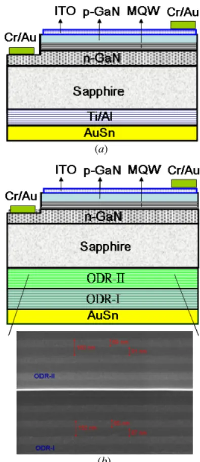
system. Figure3is a schematic diagram of our InGaN green LED with (a) a Ti/Al reflector of thicknesses 50 A/3000 A and an 80% reflectivity and (b) a composite ODR made of TiO2/SiO2. A 300 nm thick indium–tin oxide (ITO) layer
was subsequently evaporated at 300◦C onto the LED sample surfaces to serve as the upper electrical contact. The highly conductive ITO also has a high transparency, and thus a much larger light output from the LED surface can be achieved [18]. Cr/Au contact was deposited onto the exposed n-type GaN layer to serve as the n-type electrode. After lapping and polishing the samples, composite ODRs were deposited by an E-beam evaporator at the bottom. ODR-II is first deposited on the sapphire substrate and then followed by ODR-I. Each individual ODR is made up of 12 pairs of TiO2and SiO2layers.
Details of the TiO2/SiO2 deposition were described in our
previous work [16]. Finally, Au80Sn20solder was deposited at
the bottom of the reflectors to improve the thermal conduction of the LED chip.
3. Results and discussion
We performed electroluminescence (EL) measurements by injecting a continuous current into our InGaN-based green LED chips at room temperature. The light output was detected by a calibrated integrating sphere with Si photodiode on the package device (TO-46 package).
(a)
(b)
Figure 3. Schematic diagram of the InGaN-based green LEDs
(a) with a Ti/Al reflector, and (b) with our composite ODR. The inset shows the SEM picture of the ODR.
We first check the quality of our composite ODR. Figure4 shows the measured transmittances of the composite-ODR as a function of wavelength at different incident angles (0◦, 30◦, 50◦, 70◦) for unpolarized light. Up to maximum incidence angle 70◦, the transmittance falls below 0.5% for wavelengths between 500 nm and 564 nm. For even larger incident angle, the long wavelength edge of the bandgap shifts to shorter wavelength. The measured stop band will be closer to the bandgap (the region bounded by the dash lines in figure4) as predicted by our theoretical calculation.
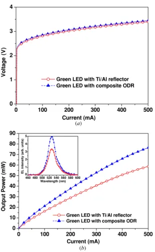
Figure 5(a) shows the forward current–voltage (I–V) characteristics. At a driving current of 300 mA, the forward voltages of the InGaN-based LED with Ti/Al reflector and the InGaN-based LED with the composite ODR were 3.16 V and 3.21 V, respectively. The slightly higher forward voltage of the LEDs with the composite ODR compared with the LEDs with Ti/Al reflector can be attributed to additional thermal processes during the deposition of the TiO2/SiO2layers. We
believe that the ITO/SPS layer interfacial mixing could result in a higher specific contact resistance and hence could raise the LEDs operation voltage.
Figure 5(b) shows the typical intensity–current (L–I) characteristics of our LEDs with Ti/Al reflector and our LEDs with the composite ODR. At an injection current of 300 mA, the light output powers of these LEDs were approximately 40.7 mW and 52.9 mW, respectively. The LEDs with the composite ODR have light extraction enhancement by 30% compared with the LEDs with Ti/Al reflector. The light
C H Lin et al
Figure 4. The measured transmittance of unpolarized light of our
composite ODR at different incident angles (0◦, 30◦, 50◦, 70◦) as a function of the wavelength.
0 100 200 300 400 500 0 1 2 3 4
Green LED with Ti/Al reflector Green LED with composite ODR
Vol tage ( V ) Current (mA) (a) (b) 0 100 200 300 400 500 0 10 20 30 40 50 60 70 80 90 460 480 500 520 540 560 580 600 0 1 2 3 4 5
EL intensity (arb. units)
Wavelength (nm)
Green LED with Ti/Al reflector Green LED with composite ODR
Out p u t Power ( m W) Current (mA)
Figure 5. The measured (a) current–voltage (I–V) and (b)
intensity–current (L–I) characteristics of the InGaN-based green LED with a composite ODR and with a Ti/Al reflector. The inset shows their room temperature EL spectra.
enhancement can be attributed to the composite ODR which has a higher reflectance, a lower absorption and a wider reflection angle compared with Ti/Al reflector. The inset in figure5(b) shows the typical room temperature EL spectra of these LEDs at a driving current of 300 mA.
To further investigate the influence of our composite ODR on the light output of our LED chips, we also measured the light
0 30 60 90 120 150 180 Angle (degree) Current 300 mA
Green LED with Ti/Al reflector Green LED with composite ODR
Figure 6. The measured far-field angular distribution of light
emitted from our green LED with a composite ODR and with a Ti/Al reflector.
output radiation patterns of our two types of LEDs at a driving current of 300 mA. The results are shown in figure6. It is clear that our green LEDs with the composite ODR have higher extraction efficiency and a wider view angle compared to LEDs with Ti/Al reflector. The detailed radiation patterns also show a stronger enhancement around the vertical direction. This enhancement is attributed to the higher reflectance of the composite ODR compared to the Ti/Al reflector.
4. Conclusion
In conclusion, we have successfully designed and fabricated InGaN-based green LEDs with composite ODRs. The composite ODR is made up of two ODRs stacked back-to-back. It is designed to have very high reflectivity at wavelengths from 498 nm to 548 nm. With the LED emission peak at about 525 nm with a FWHM of 35 nm and a driving current of 300 mA, it is found that the light output powers of the LEDs with composite ODRs and the LEDs with Ti/Al metal reflectors are about 52.9 mW and 40.7 mW, respectively. The 30% light extraction enhancement can be attributed to the higher reflectivity, lower absorption and a wider reflection angle compared with Ti/Al reflector. Our work offers a promising potential for enhancing output powers of green light-emitting devices.
Acknowledgments
The authors are grateful to Professor S C Wang and T C Lu (NCTU) for their contribution to this work. This work was supported in part by the National Science Council of Republic of China (ROC) in Taiwan under contract no. NSC 92-2215-E-009-015, NSC 92-2112-M-009-026 and by the Academic Excellence Program of the ROC Ministry of Education under contract no. 88-FA06-AB. Also one of the authors (KML) wishes to thank the United States Army Research Office for partial support under grant W911NF-04-1-0231.
References
[1] Nakamura S, Senoh M, Iwasa N and Nagahama S 1995 High-brightness InGaN blue, green and yellow
light-emitting diodes with quantum well structures Japan. J.
Appl. Phys.34 L797
[2] Nagahama S et al 2001 GaN-based light-emitting-diodes and laser diodes, and their recent progress Phys. Status Solidi
a188 1
[3] Ji L W, Fang T H and Meen T H 2006 Effects of strain on the characteristics of InGaN-GaN multiple quantum-dot blue light emitting diodes Phys. Lett. A355 118
[4] Ray S K, Groom K M, Liu H Y, Hopkinson M and Hogg R A 2006 Broad-band superluminescent light emitting diodes incorporating quantum dots in compositionally modulated quantum wells Japan. J. Appl. Phys.45 2542
[5] Hatami F, Masselink W T, Lordi V and Harris J S 2006 Green emission from InP-GaP quantum-dot light-emitting diodes
IEEE Photon. Technol. Lett.18 895
[6] Chen H S, Hsu C K and Hong H Y 2006 InGaN–CdSe–ZnSe quantum dots white LEDs IEEE Photon. Technol. Lett.
18 193
[7] Misra A, Kumar P, Kamalasanan M N and Chandra S 2006 White organic LEDs and their recent advancements
Semicond. Sci. Technol.21 R35
[8] Guo C, Huang D and Sub Q 2006 Methods to improve the fluorescence intensity of CaS:Eu2±red-emitting phosphor for white LED Mater. Sci. Eng. B130 189
[9] Heliotis G, Gu E, Griffin C, Jeon C W, Stavrinou P N, Dawson M D and Bradley D D C 2006 Wavelength-tunable and white-light emission from polymer-converted micropixellated InGaN ultraviolet light-emitting diodes
J. Opt. A: Pure Appl. Opt.8 S445–9
[10] Do Y R, Koa K Y, Na S H and Huhb Y D 2006 Luminescence properties of potential Sr1−xCaxGa2S4:Eu green- and
greenish-yellow-emitting phosphors for white LED
J. Electrochem. Soc.153 H142
[11] Yeh S J, Chen H Y, Wu M F, Chan L H, Chiang C L, Yeh H C, Chen C T and Lee J H 2006 All non-dopant red–green–blue composing white organic light-emitting diodes
Org. Electron.7 137
[12] Piao X, Horikawa T, Hanzawa H and Machida K 2006 Characterization and luminescence properties of Sr2Si5N8:Eu2±phosphor for white
light-emitting-diode illumination Appl. Phys. Lett. 88 161908
[13] Ishikawa T, Sakata S and Mitani A 2006 Durable, ultraluminous structure for incandescent, high-power white-LED Int. J. Appl. Ceram. Technol.3 144
[14] Krummacher B C, Choong V E, Mathai M K, Choulis S A and So F 2006 Highly efficient white organic light-emitting diode Appl. Phys. Lett.88 113506
[15] Shen F, He F, Lu D, Xie Z, Xie W, Ma Y and Hu B 2006 Bright and colour stable white polymer light-emitting diodes Semicond. Sci. Technol.21 L16
[16] Lin C H, Leung K M and Tamir T 2002 Modal
transmission-line theory of three-dimensional periodic structures with arbitrary lattice configurations J. Opt. Soc.
Am. A 19 2005
[17] Pan S M, Tu R C, Fan Y M, Yeh R C and Hsu J T 2003 Improvement of InGaN–GaN light-emitting diodes with surface-textured indium–tin–oxide transparent Ohmic contacts IEEE Photon. Technol. Lett.