Manuscript received January 14, 2005 0098 3063/05/$20.00 © 2005 IEEE H.264. Specifically, to efficiently use the bus bandwidth, we
classify the filtering mode into 8 types and use an adaptive transmission scheme to avoid redundant data transfer. Moreover, to reduce the processing latency, we use a bus-interleaved architecture for conducting data transmission and filtering in parallel. As compared to the state-of-the-art designs, our scheme offers 1.6x to 7x performance improvement. While clocking at 100MHz, our design can support 2560x1280@30Hz processing throughput. The proposed design is suitable for low cost and real-time applications. Moreover, it can be easily applied in system-on-chip design.
Index Terms — H.264 de-blocking filter, loop filter, AVC.
I. INTRODUCTION
H264, also known as MPEG-4 AVC [7], has been proven to have much better visual quality as compared to the existing standards such as MPEG-1, -2, -4, H.263 and so on. Among various coding tools in H.264, the in-loop de-blocking filtering has most significant impact on the visual quality improvement. To reduce the blocking artifact, the in-loop de-blocking filter adaptively conducts the filtering along the boundaries of each 4x4 block according to the boundary strength (bS), the quantization parameter (Qp) and the content of the block. The blocking artifact is removed. However, the improvement is at the cost of intensive computation and memory access.
For real-time applications, the de-blocking filtering becomes one of the performance bottlenecks. In [1]-[5] dedicated hardware was developed for acceleration. Specifically, the architecture of [5] is for frame-based filtering. The de-blocking filtering is invoked after the reconstruction of the entire frame. Apparently, frame-based filtering requires a frame buffer and longer system latency. To reduce the buffer size and latency, [1]-[4] proposed a macroblock-based (MB-based) filtering architecture. The filtering can be started upon the reconstruction of a MB. To achieve high throughput, in [2], [4] two-ported SRAMs are used to simultaneously conduct the reading and writing during the filtering. However, the high throughput is at the cost of complex and costly memory architecture. In addition, for filtering a MB, [2], [4] need to first buffer the entire MB. The hardware is idled for waiting the data. Moreover, the data movement of [2]-[5] is not mode aware which means that the transmission overhead is not
minimized. Hence, in this paper, we propose a parallel processing architecture and a more efficient data transmission scheme to improve the performance.
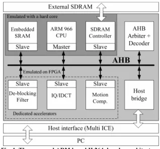
In this paper, we propose a platform-based architecture for de-blocking filtering. Fig. 1 shows an overview of our H.264 decoder platform [6]. Mainly, it includes an ARM9 CPU for the data flow control and several dedicated accelerators for the computation intensive tasks. The CPU communicates with the accelerators via a 32-bit AHB bus. For the de-blocking filtering, there are intensive data transmissions among CPU, embedded memory and the accelerator. To reduce the bus workload, we classify the filtering modes of a MB into various types. According to the filtering type distribution, we propose an adaptive transmission scheme. As compared to [2]-[5], the bus bandwidth requirement of our design is reduced to 11% to 55% of [2]-[4] and 6% to 28% of [5]. Moreover, to reduce the processing latency, we develop a bus-interleaved architecture. As compared to [2], [3], [4], and [5], our design uses simpler single-ported memory and averagely offers 1.6x to 7.1x improvement on processing latency.
The remainder of this paper is organized as follows. Section II introduces the algorithm of de-blocking filtering in H.264. Section III describes our adaptive transmission scheme and shows its benefits. Section IV illustrates our bus-interleaved architecture and its operation. Section V gives the processing latency comparisons of different designs. Section VI presents the comparison of hardware design, memory access frequency and system performance. Lastly, Section VII concludes this work and shows the applications.
II. ALGORITHM OF DE-BLOCKING FILTERING
The in-loop de-blocking filter in H.264 [7] is designed to reduce the blocking artifacts. The filter operation is applied to each edge of a 4x4 block. Fig. 2 shows the edge filtering order within a 16x16 luminance MB. As shown, the vertical edges are filtered first and then the horizontal ones. In addition, for filtering an edge of a 4x4 block, consecutive 8 pixels from the same row (or column) of two adjacent 4x4 blocks are required. For example in Fig. 2, the pixels (A0-A3, B0-B3) are accessed for the vertical (or horizontal) filtering of a 4x4 block. Particularly, each sample pixel of (A0-A3, B0-B3) is filtered adaptively by different filter taps.
To decide the filter tap for each pixel, the following factors are used:
1. Boundary strength (bS). 2. Thresholds of α and β. 3. The content of sample pixels.
Fig.3 elaborates the detail about how these factors are used to decide the filter tap for each pixel of (A0-A3, B0-B3). As shown, the first step is to use (1) for deciding whether the filtering is required or not. Then, according to the bS level, thresholds (α, β) and the absolute differences of adjacent reconstructed pixels, different filters are applied to different pixels. Specifically, in Fig. 3, not all the input pixels (A0-A3, B0-B3) will be updated with the filtered results. For example, if bS is not of strongest level, only A0, B0, A1, B1 are updated. For those pixels without update, the original pixel values are unchanged. The process is continued by sliding the filtering window one block to the right (or to the bottom) at a time as in Fig. 2. Note that the updated (B0-B3) could be used for the filtering of next adjacent block when the filtering window slides one block to the right (or to the bottom).
bS!=0 AND |A0–B0|<α AND |A1–A0|<β AND |B1–B0|<β (1) In Fig. 3, the bS level is mainly used to decide the necessity of filtering and filter type. In H.264, the bS has 5 levels. The
Fig. 4. Decision flow of boundary strength (bS) where P and Q denote the identifications of two adjacent 4x4 blocks.
Fig. 5. The MB data and its adjacent blocks used for MB based de-blocking filtering.
Fig. 2. The sequential order for filtering the edges of 4x4 blocks in a luminance MB.
actual level is determined by the MB type, edge position, reference frame type, and motion vectors of two adjacent blocks. Fig. 4 shows the decision of bS level. As shown, the strongest bS level, i.e., bS=4, is identified when two adjacent blocks are intra coded and locate at the MB boundary. In this case, obvious blocking artifact could be noticed. As a result, higher bS level invokes stronger low pass filtering. On the other hand, when the bS is at the weakest level, i.e., bS=0, there is no filtering.
In addition to the bS level, the parameters (α, β) are used to preserve the real edge. In (1), the necessity of filtering is also controlled by the parameters (α, β). Specifically, α and β are assigned with higher values to increase the possibility of filtering as higher quantization parameter causes more noticeable blocking artifact. In contrast, smaller α and β are used for lower quantization parameter.
III. ADAPTIVE MACROBLOCK TRANSMISSION SCHEME
In this paper, our de-blocking filtering is designed to operate at MB level. The entire frame is filtered in a MB-by-MB manner and the MB-by-MBs within a frame are processed in a raster scanning order. The filtering can be started upon the reconstruction of a MB. For filtering a MB, we need to first retrieve the reconstructed data from the memory (or certain module) and send it to the dedicated accelerator via a bus. As more and more dedicated accelerators are deployed, the limited and shared bus bandwidth could become the performance bottleneck. To reduce the demand of bus bandwidth, we propose an adaptive MB transmission scheme.
A. MB Mode Classification
Fig. 5 depicts the data required for filtering a MB. As shown, in addition to current MB, the adjacent 4x4 blocks at the right and left boundaries are also needed. In [2]-[5], all the data as depicted in Fig. 5 are transferred to the de-blocking filter accelerator. However, we find that not all 4x4 blocks within a MB need to be filtered. We can more efficiently use the bus bandwidth by minimizing the redundant data transfer. To do so, we define 8 MB filtering modes according to the filtering requirements of left MB boundary, upper MB boundary and current MB. Table I summarizes the corresponding data size
of each mode. For example, mode 5 denotes the case in which only the left and the top MB boundaries are required for filtering. As a result, for the luminance part, we simply need the adjacent 4 blocks in the left MB, the adjacent 4 blocks in the upper MB and the adjacent 7 blocks in current MB. By the same token, we can derive the data size for the chrominance part. Totally, the data size of mode 5 is 100 words including 60 words for luminance component and 40 words for chrominance component. Following the same principle, one can derive the data size for the other modes. By distinguishing different filtering modes, we can minimize the redundant data transfer.
B. MB Filtering Mode Distribution
Fig. 6 shows the mode distribution of Akiyo and Foreman sequences based on JM6.0. Without mode classification, [2]-[5] treat all MBs as mode 1, i.e., all the input samples shown in Fig. 5 are transferred. However, from Fig. 6, we learn that mode 1 is actually less than 30%. Moreover, in the extreme case of Akiyo, most MBs use skip mode that does not require any input samples. Thus, [2]-[5] actually incur many redundant data transfer. With the filtering mode classification, we can more efficiently use the bus bandwidth. According to the mode distribution, in Akiyo sequence, we can save 89% of data transfer used in [2]-[4] and 94% of that in [5]. Similarly, in Foreman sequence, our design can save 45% of data movement used in [2]-[4] and 72% of that in [5]. Significant data transfer reduction is achieved.
IV. BUS-INTERLEAVED ARCHITECTURE
To reduce the processing latency, we propose a bus-interleaved architecture in [1]. Specifically, we perform the filtering and the data transfer in parallel. Different from prior designs [2], [4], and [5], the filtering can be started while the data is being streamed in and out. The processing latency is reduced due to the parallelism.
A. Proposed Bus-interleaved Architecture
Fig. 7 shows our proposed architecture. It mainly includes four components:
Fig. 6. MB filtering mode distribution in Akiyo and Foreman sequences coded at QCIF@15fps 64Kbps with JM6.0.
Skip N N N 0
*: The MB boundary required for filtering. **: Data transfer size in words.
1. One-dimensional Adaptive FIR Filter
The one-dimensional FIR filter adaptively performs the horizontal/vertical filtering in a row-by-row manner. For each row, it takes 8 input samples from two adjacent 4x4 blocks to conduct filtering. Accordingly, it produces 4 filtered results and 4 intermediate results for the filtering of next block.
2. Single-ported SRAM
A single-ported SRAM is used as a local memory for buffering the horizontally filtered and transposed MB. Specifically, it stores all the 4x4 blocks in current MB (i.e., 96x32 bits) and the adjacent 4x4 blocks in the upper and left MBs (,i.e., 44x32 bits). The total size of the SRAM is 140x32 bits.
3. 4x4 Pixel Arrays (Reg1 and Reg2)
In Fig. 7, Reg1 buffers the intermediate results produced by the FIR filter. On the other hand, Reg2 acts as a transposed memory. Particularly, Reg2 performs the transposition by storing the data in either Horizontal-In-Vertical-Out or Vertical-In-Horizontal-Out fashion. Fig. 8 shows an example of the transposition where Row(n, Bm) represents the n-th row of m-th block and Col(n, Bm) denotes the n-th column of m-th block. Specifically, Fig. 8 (a) depicts the case as the horizontally filtered Block 0 is being written to Reg2 in a
row-by-row manner. After Block 0 is completely buffered in Reg2, Fig. 8 (b) illustrates that the transposition is done by writing Block 0 to the SRAM in a column-by-column manner. Particularly, after Col(1, B0) is stored in the SRAM, we filled out the left space in Reg2 with Row(1, B1), i.e., the first row of next horizontally filtered block. Such replacement is continued until horizontally filtered Block 1 is completely buffered in Reg2. Since Block 1 is stored column-by-column in Reg2, we transpose Block 1 by outputting the data row-by-row to the SRAM. Such cyclical rotation between Horizontal-In-Vertical-Out and Vertical-In-Horizontal-Out is conducted throughout the entire de-blocking process. Traditional designs [2], [4], and [5] require stalls for block transposition. However, our seamless design requires no stalls.
4. Data Flow Control Unit
The data flow control unit consists of a finite state machine which controls synchronization among 1-D FIR filter, 4x4 pixel arrays and local SRAM buffer. Moreover, it responses to the de-blocking filtering request from the AHB bus. B. Operation of Bus-interleaved Architecture
To describe the operation of our bus-interleaved architecture, we use the filtering of a mode 1 MB as an example. Fig. 9 shows the processing order of horizontal and vertical filtering for a MB of mode 1 and Fig. 10 shows the corresponding block input order to the dedicated hardware. In Fig. 11, we show the status of our bus-interleaved architecture during the horizontal filtering. Here, we assume Reg1 has buffered the unfiltered samples of Block 0. To perform the horizontal filtering for the edge between Block 0 and Block 1
Fig. 7. The proposed bus-interleaved architecture.
Fig. 8. Operation of the transposed memory (Reg2).
Fig. 9. The edge processing order of (a) horizontal filtering (b) vertical filtering in a luminance MB.
in Fig. 10, the FIR filter takes Row(1,B1) from the bus and Row(1,B0) from the 1st row of Reg1 for computation. After the filtering, we overwrite the 1st row of Reg1 with the
intermediate results, Row(1,B1)_intermediate, and save the horizontally filtered results, Row(1,B0)_h, in the 1st row of
Reg2. The other rows are processed in the same way. When the horizontally filtered Block 0 is completely stored in the Reg2, we transpose the block by writing it to the SRAM in a column-by-column fashion. While the SRAM is being written, the FIR filter performs the horizontal filtering for the edge between Block 1 and Block 2 by receiving Row(n,B2) from bus and retrieving Row(n,B1)_intermediate from Reg1. Such process is continued until the horizontal filtering of a MB is done. After the horizontal filtering, we read the horizontally filtered MB from the SRAM and perform the vertical filtering in the same manner. Specifically, during the vertical filtering, the input data of FIR filter is now configured to be from the SRAM. In addition, the filtered and transposed data is written
to the CPU instead of local SRAM. Fig. 12 shows the configuration of our bus-interleaved architecture during the vertical filtering.
C. Overlapping of bS Level Calculation
In our design, vertical filtering can only be initiated until the last horizontally filtered block buffered in Reg2 is completely written to the SRAM. This constraint is posed by the fact that single-ported SRAM cannot simultaneously perform writing and reading. While the last horizontally filtered block buffered in Reg2 is being written to the SRAM, the FIR filter is stalled. During this turn-around time, we calculate the bS level for the next MB so that the average processing latency of a MB can be further reduced.
V. PROCESSING LATENCY ANALYSIS
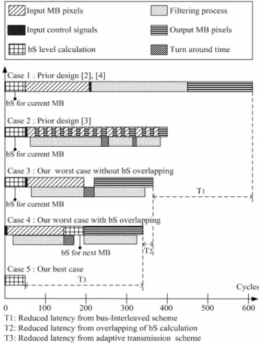
Fig. 13 shows the comparisons of the MB processing latency in different approaches. For filtering a MB, the Case 1 shows the processing latency of [2], [4] and the Case 2 illustrates the one of [4] which also includes 50 bS calculation cycles. Accordingly, the Case 3 depicts the latency of our design in worst case. Note that the worst case of our design occurs when we have MB type of mode 1 which requires most of data transmission. Due to the parallelism of data transmission and filtering, Fig. 13 shows that our design is 1.7 times faster than [2], [4]. Moreover, with the overlapping of bS calculation, the Case 4 shows that the processing latency can be further reduced. In addition, the Case
Fig. 11. Data flow of horizontal filtering in the bus-interleaved architecture.
Fig. 12. Data flow of vertical filtering in the bus-interleaved architecture.
5 illustrates that our best case is 7.7X faster than [3] and 12X faster than [2], [4]. In the best case, the skip mode is detected. There is no need to conduct data movement between the memory and the accelerator. With mode classification, our design can detect skip mode and avoid the redundant data movement. However, without mode aware, traditional design [2]-[4] requires redundant data movement even in skip mode.
Table II lists the cycle counts of each mode in our design. In addition, Fig. 14 shows the average cycle counts for processing a MB in different sequences. As shown, our design averagely requires 86 to 241 cycles for filtering a MB while the works in [2], [4]-[5] need more than 600 cycles. Significant latency improvement is achieved.
VI. EXPERIMENTS
In this Section, we show the comparisons of different hardware designs. Moreover, we analyze the memory access frequency in different approaches. Lastly, we use an ARM based H.264 decoder as an example to demonstrate the system performance of our design.
A. Comparison of Hardware Implementation
Table III compares our accelerator with the state-of-the-art designs in [2]-[5]. As shown, for filtering a MB, our design requires less cycle counts. Specifically, as compared to [2], [4], and [5], we provide 2.5x to 7.1x performance improvement with simpler and smaller single-ported memory. In addition, as compared to [3], we have 1.6x to 4.5x performance improvement. While clocking at 100MHz, our design can support 2560x1280@30Hz processing throughput. Additionally, our bus bandwidth requirement is down to 11% to 55% of [2]-[4] and 6% to 28% of [5]. For the memory size, our work is a bit
bigger than that in [3]. However, we can reduce the memory size to 96x32 bits without increasing the processing latency by sharing the memory for the luminance and chrominance filtering. Currently, we separately allocate memory for the luminance and chrominance components. However, in our bus-interleaved architecture, the filtering of luminance and chrominance components is done sequentially. Thus, we can actually reduce the local memory size by sharing the memory.
B. Comparison of Memory Access Frequency
Table IV further compares the local SRAM access frequency of different approaches. For filtering a MB, both [2], [4] and [5] require memory read and write operation for input sample buffering, horizontal filtering and vertical filtering. On the other hand, our design simply needs one write operation for horizontal filtering and one read operation for vertical filtering. Significant memory access reduction is achieved. Less frequent memory access and simpler memory architecture bring the advantages of lower power consumption and lower cost.
C. System Performance Evaluation
In Table V, we show the system performance comparison using H.264 decoder. Table VI shows the encoder parameters. Specifically, we use our prior work [6] as the baseline. In [6], we implemented two dedicated accelerators for IQ/IDCT and
TABLE III
COMPARISON OF DEDICATED HARDWARE DESIGN
[2], [4] [3] [5] Our design Latency per MB (cycles) 614 386 >600 86 - 241 Memory Architecture
Two-port Single-port Two-port Single-port
Memory Size (Bits) 96x32 +64x32 80x32 Frame size 140x32 (96x32 after reduction) Bandwidth Requirement (Normalized factor with respect to [5]) 50% 50% 100% 6% - 28% Processing Rate (100MHz) 1280x720@ 30Hz 2048x1024 @30Hz 1280x720 @30Hz 2560x1280 @30Hz Gate Count with UMC 0.18 um 20.6K 9.2K N/A 11.8K TABLE IV
COMPARISONS OF LOCAL MEMORY ACCESS FREQUENCY [2], [4], [5] Our design, [3] Read/Write for
Input Sample
Buffering Read/Write None
Read/Write for
Horizontal Filtering Read/Write Write Read/Write for
Vertical Filtering
Read/Write Read
TABLE II
LATENCY OF DIFFERENT TRANSMISSION MODES Transmission Mode Latency Per MB (cycles)
1 342 2 310 3 310 4 246 5 254 6 182 7 182 SKIP 50 0 100 200 300 400 500 600
Coast Foreman Mother Container Akiyo Test Sequeces Cy cles P er M B Prior Work[2] Our Design
motion compensation. Also, we use optimized software for the other tasks. In this work, we additionally add the accelerator for de-blocking filter. In this system, the ARM966 CPU is running at 130MHz and the FPGA module is running at 20MHz. As shown, the performance improvement is sequence dependent. For Coastguard and Foreman, we show 25% to 30% throughput improvement. However, in Akiyo and Container sequences, the improvement is minor because most of MBs are skip modes. As compared to the software implementation, our performance gain mainly comes from the bus-interleaved architecture and hardware acceleration. In skip mode, the filtering is not applied. That is why our dedicated hardware has minor improvement in Akiyo and Container sequences. In contrast, as compared to the other hardware implementations [2]-[5], skip mode will have huge benefits as shown in Fig. 13 because our mode aware design can avoid the latency caused by the redundant data transfer.
VII. CONCLUSION
In this paper, we present a platform based bus-interleaved architecture for de-blocking filter in H.264. We have shown that performing the data transmission and filtering in parallel can significantly reduce the processing latency. Moreover, classifying MB filtering mode can avoid redundant data transfer. In addition, we use an ARM based H.264 decoder to demonstrate the feasibility of our design. The proposed design is suitable for low cost and high performance multimedia applications. Also, it can be quickly integrated into the ARM based system-on-chip design.
REFERENCES
[1] S. C. Chang, W. H. Peng, S. H. Wang and T. Chiang, “A Platform Based Bus-interleaved Architecture for De-blocking Filter in H.264/MPEG-4 AVC”, IEEE Int’l Conf. on Consumer Electronics, 2005.
[2] T. C. Chen, Y. W. Huang, C. H. T, T. W. Chen and L. G. Chen, “A 1.3 TOPS H.264/AVC single-chip encoder for HDTV applications“, IEEE Int’l Solid-State Circuits Conf., 2005
[3] C. C. Cheng and T. S. Chang, “An hardware efficient deblocking filter for H.264/AVC”, IEEE Int’l Conf. on Consumer Electronics, 2005.
Shih-Chien Chang was born in Taichung, Taiwan in
1981. He received the B.S. degree in Electronics Engineering from National Chiao-Tung University, Hsinchu, Taiwan, in 2003, where he is currently working toward the M.S. degree in the Institute of Electronics. His research interests are video compression and VLSI implementation.
Wen-Hsiao Peng received the B.S. and M.S. degrees in
Electrics Engineering from National Chiao-Tung University, Taiwan, in 1997 and 1999 respectively. During 2000-2001, he was an intern in Intel Microprocessor Research Lab, U.S.A. In 2002, he joined the Institute of Electric Engineering of National Chiao-Tung University, where he is currently a Ph.D candidate. His major research interests include scalable video coding, embedded entropy coding, video codec optimization and platform based architecture design for video coding applications. Since 2000, he has been working with video coding development and implementation. He has actively contributed to the development of MPEG-4 Fine Granularity Scalability (FGS) and MPEG-21 Scalable Video Coding.
Shih-Hao Wang was born in Tainan, Taiwan, R.O.C. in
1977. He received the M.S. degree in Electrical and Control Engineering from National Chiao-Tung University, Hsinchu, Taiwan, in 2001, where he is currently working toward the Ph.D. degree in the Institute of Electronics. His research interests are video compression and VLSI implementation.
Tihao Chiang was born in Cha-Yi, Taiwan, Republic of
China, 1965. He received the B.S. degree in electrical engineering from the National Taiwan University, Taipei, Taiwan, in 1987, and the M.S. degree in electrical engineering from Columbia University in 1991. He received his Ph.D. degree in electrical engineering from Columbia University in 1995. In 1995, he joined David Sarnoff Research Center as a Member of Technical Staff. Later, he was promoted as a technology leader and a program manager at Sarnoff. While at Sarnoff, he led a team of researchers and developed an optimized MPEG-2 software encoder. For his work in the encoder and MPEG-4 areas, he received two Sarnoff achievement awards and three Sarnoff team awards. Since 1992 he has actively participated in ISO's Moving Picture Experts Group (MPEG) digital video coding standardization process with particular focus on the scalability/compatibility issue. He is currently the co-editor of the part 7 on the MPEG-4 committee. He has made more than 90 contributions to the MPEG committee over the past 10 years. His main research interests are compatible/scalable video compression, stereoscopic video coding, and motion estimation. In September 1999, he joined the faculty at National Chiao-Tung University in Taiwan, R.O.C. Dr. Chiang is currently a senior member of IEEE and holder of 13 US patents and 30 European and worldwide patents. He was a co-recipient of the 2001 best paper award from the IEEE Transactions on Circuits and Systems for Video Technology. He published over 50 technical journal and conference papers in the field of video and signal processing.
ENCODER PARAMETERS FOR EXPERIMENTS
Frame Size QCIF
Frame Rate 15fps
Qp I(28)P(31) Group of Picture 1I + 149P


![Table III compares our accelerator with the state-of-the-art designs in [2]-[5]. As shown, for filtering a MB, our design requires less cycle counts](https://thumb-ap.123doks.com/thumbv2/9libinfo/7761395.149456/6.918.76.433.92.479/table-compares-accelerator-designs-filtering-design-requires-counts.webp)
