Performance study for a Mobile TCP under Fading Channel
7
0
0
全文
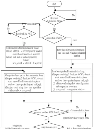
(2) non-selective multi-path fading. 3.. Proposed solution. The main impact factors concerned with the M_TCP performance include burst packet loss caused by network congestion, wireless link error and handoff. The network is congested due to heavy load or insufficient buffer space at a node. Once the network is congested, the transmission rate should be reduced moderately at the sender. On the other hand, it is unnecessary to reduce the transmission rate when wireless link error or handoff causes packet loss. Based on these observations, the results concerned with packet loss can be divided into two classes including network congested one and non-network congested one. Accordingly, we propose a Burst Loss Retransmit Algorithm (BLRA) to define two retransmission phases so that the algorithm can recover multiple packet losses. Moreover, the algorithm proposes different schemes to initiate the parameters including congestion window (cwnd) and slow start threshold (ssthresh) to improve system performance when retransmission phase reaches a timeout. The algorithm is shown in Figure 1(a). In the following subsection, we will describe the operation concerned with the two retransmission phases of BLRA. 3.1. Retransmission phase. Since the statuses are dissimilar due to packet loss, thus the machine that handles the recovery process is also different. The BLRA defines two retransmission phases called Congestion Fast Retransmission phase and Error Fast Retransmission phase to provide the solution for various situations. Either of the phases will be actuated when packet loss is due to network congestion and wireless link error or handoff, respectively. In the Congestion Fast Retransmission phase, the lost packets will be retransmitted if network was congested. Otherwise, the lost packets that are due to wireless link error or handoff will be retransmitted in the Error Fast Retransmission phase. The procedures concerned with two retransmission phases are discussed in the following. Firstly, the base station compares the sequence number of passing packets to distinguish these two cases (i.e. due to congestion or wireless loss). Once an error is caused by wireless link, the passing ACK is put an error signature on the unused bit of Type Of Service (TOS) of Internet Protocol (IP) header by the base station. Thus, the BLRA that actuates at the sender can enter suitable retransmission phase to recover lost packets when the sender receives an ACK. According to Stevens’s Fast Retransmit algorithm [1], if three or more duplicate ACKs are received successively, it is a strong indication that a segment has been lost then the sender performs a retransmission without waiting for a retransmission timer to expire. On the other hand, there will be only one or two duplicate ACKs before the reordered segment is processed. Hence, in this case (i.e. loss due to congestion) the BLRA applies the rule to actuate the Congestion Fast Retransmission phase. On the other case that packet loss is due to wireless link error or handoff, for the sake of efficiency, we introduce the Error Fast Retransmission phase which is actuated if the sender receives two duplicate ACKs. successively. Once the sender receives two duplicate ACKs, the BLRA is performed and discriminates different cases by the error signature shown in Figure 1(a). If an error is recognized, the Error Fast Retransmission phase is actuated, then it enters the Error burst packet Retransmission loop to retransmit multiple lost packets. Otherwise, if the third ACK is received then a Congestion Fast Retransmission phase is actuated, so the BLRA enters the Congestion burst packet Retransmission loop to retransmit multiple lost packets caused by network congestion. Furthermore, the action concerned with recovering the lost packets is to send one packet immediately once the sender receives two ACKs until all lost packets are retransmitted. This action has the capability that mitigates the congestion again. Once the network loses packets, the BLRA is notified whether it is due to network congestion, wireless link error or handoff. However, in Hoe’s algorithm [6], there is no difference for these three cases. The sender sets the size of slow start threshold to one-half value of congestion window and reduces the value of congestion window to one, then it enters the retransmission phase. However, this way is not suitable for packet loss that happens in wireless network. Hence, the BLRA has the ability to discriminate different status. Based on different situation, the parameters of transmission rate related to congestion window and slow start threshold can be adjusted properly in the BLRA. Briefly, in the Congestion Fast Retransmission phase, the value of initial cwnd and ssthresh are kept the same as the prototype Fast Retransmit algorithm [1]. Once the network is congested, one-half of the current cwnd size is saved in the ssthresh and the cwnd is set to one segment. Additionally, the highest sequence number of transmitted packets is saved in the snd_high and the save_cwnd is set to ssthresh plus one segment. The action of save_cwnd value can avoid the congestion appearing again quickly caused by too large congestion window once leaving the retransmission phase. On the other hand, it is not suitable to reduce the transmission rate in the Error Fast Retransmission phase. That is to say, to modify the initial parameters of transmission rate including cwnd and ssthresh is unnecessary in this situation. Hence, the BLRA only saves the highest sequence number of transmitted packets. 3.2 Retransmission Loop The retransmission loop is performed to recover multiple packet loss after the BLRA sets the initial cwnd and ssthresh. There are two Retransmission loops called Congestion burst packet Retransmission loop and Error burst packet Retransmission loop for different cases. In the retransmission loops, upon receiving two duplicate ACK’s, the sender sends out one new packet whose sequence number is beyond snd_high. This action has the effect that avoids the congestion while in the retransmission phase. Additionally, the method of adjusting cwnd in two retransmission loops follows the same idea of the slow start as [1]. But different actions are taken in these cases. Firstly, the initial value of cwnd is one in the Congestion burst packet Retransmission loop. Once the sender receives two ACKs, then it sends out a packet and adjusts the.
(3) cwnd to two. The cwnd is adjusted to four once the sender receives another two more ACKs. Afterwards, the cwnd will be adjusted again once the sender receives every two more ACKs. Hence, it is increased exponentially as long as the cwnd is less than or equal to save_cwnd. Otherwise, the cwnd does not increase anymore. On the other hand, in the Error burst packet Retransmission loop, the initial value of cwnd does not change if the BLRA enters the Error Fast Retransmission phase. Afterwards, once the sender receives two more ACKs, the cwnd is increased exponentially as long as the cwnd is less than or equal to ssthresh. Otherwise, the cwnd is incremented by one each time when two more ACKs are received. 3.3. Retransmission Timeout Problem. A lost packet can be recovered once the sender receives two ACKs in the retransmission phase. The purpose is to avoid congestion again when the sender is in the retransmission loop. However, it also invokes the disaster when the network has great amount of lost packets and the inter-nodes only have a few packets left. That is to say, it is possible that no ACK reaches the sender from the mobile host due to empty inter-nodes. Accordingly, the problem called retransmission timeout occurs. Under this situation, there is nothing to do but waiting for timeout. Based on the algorithm of the original TCP protocol, it mistakes for that congestion occurs. Thus, the TCP protocol actuates the timeout retransmission to continue the recovery process. More specifically, one-half of the current cwnd size is saved in ssthresh and the cwnd is set to one segment, and then invoke the slow start procedure. However, this action is different from real transmission timeout because the mobile host does not receive any packet due to empty inter-nodes and no ACK is transmitted to the sender. Thus, how to control the congestion window to improve the performance is another task to study. Once a timeout occurs during the retransmission phase, the BLRA proposes different algorithm. It is still in the retransmission phase and switches from the Congestion burst packet Retransmission loop or the Error burst packet Retransmission loop to the timeout loop shown in Figure 1(b). Furthermore, it initiates the cwnd and ssthresh by another scheme. Briefly, in the timeout loop, the adjustment of congestion window is conformed with slow start and congestion avoidance algorithm, and a new packet is sent out that follows current congestion window. For example, if the retransmission timeout occurs, the size of cwnd is four and the sender has sent out four packets. Since it receives an ACK, the cwnd is adjusted to eight then sends out five packets if three non-ACK packets are left. Once the cwnd is large than ssthresh, it is increased by one each time when an ACK is received. Furthermore, we also propose several schemes to initiate the cwnd and ssthresh when the retransmission timeout occurs in the proposed BLRA as follows. Scheme 1 : cwnd and ssthresh unchanged. Scheme 2 : cwnd' = 1/2 cwnd, ssthresh' = 1/2 ssthresh. Scheme 3 : cwnd' = 1/4 cwnd, ssthresh' = 1/2 ssthresh. Scheme 4 : cwnd' = 1/8 cwnd, ssthresh' = 1/2 ssthresh. Where cwnd' indicates new congestion window and. ssthresh' indicates new slow start threshold. 4.. Numerical Results. In this section, we shall evaluate system performance by simulation. Firstly, the simulation topology is shown in Figure 2, where the bandwidth between sender and base station is 10Mbps, and it is 2Mbps between base station and mobile host. Moreover, the buffer size of base station is 40 packets and the size of transferred packet is 512 bytes. Several conditions including error free, random error in wireless link, slow fading channel and fast fading effect, and handoff will be studied in the performance evaluation. If an error occurs in the wireless link and only one packet is suffered, this is called random error in our study. The probability of the random error follows a uniform distribution in this study, and several probability values in the range from 0.001 to 0.05 are adopted to explore the performance. In another case that mobile hosts exist under a fading channel, burst error occurrence rate (NRS) and burst error length (Tf) in [16] are adopted to study the influence to system performance. N. T. f. RS. =. =. 2 π. 1 R 2 π æç S è. f. d. æ ç è. R S 2 σ. é ê exp ö f ë ÷ d 2σ ø. ö ÷ exp. æ R S2 çç 2 è 2σ. æ çç − è. R 2 σ. ö. 2 S 2. ⋅ ⋅ ⋅ (1. ). ù ö ÷÷ − 1 ⋅ ⋅ ⋅ (2 ) ø. where σ is average signal level, fd is maximal Doppler shift and Rs is a threshold level. Thus, the respective burst error occurrence rate and burst error length can be obtained under various conditions in terms of different fD and Rs. In addition, we assume that the average signal level is higher than the threshold level by 5dB ~ 30dB. Moreover, the fading rate is assumed to be 1.34, 10, 40 and 80 Hz, respectively. Once the burst error occurrence rate and burst error length are obtained, the error probability associated with wireless link and the amount of suffered packets can be determined to explore the system performance. Finally, the impact of performance concerned with handoff is explored. Usually, the coverage of base station is 200 meters, thus the incidence of handoff is one every one-minute or five-minutes since the speed of movement speed is 12KM/hour or 2.4KM/hour respectively. Also, this study adopts different handoff pause time (e.g. 50ms, 100ms and 800ms) to measure the system performance. 4.1. Error free condition. Firstly, we measure the TCP performance while only network congestion occurs to observe the improvement using the BLRA. Figure 3 compares the throughput of the original TCP, results by Hoe [6] and our proposed schemes. It exhibits that the mean received packets using our scheme 2 and scheme 3 are more than the original TCP (increase by 27.88 % and 28.66 %, respectively) and Hoe’s (increases by 24.96 % than the original TCP). While the increment using scheme 1 and scheme 4 still get 24.63 % and 27.27 %. By the way, we measure the network congestion occurrence rate and congestion window to study further. Firstly, we measure the number of congestion during simulation time for Hoe and each scheme of BLRA, and normalize these quantities by the number of.
(4) congestion for the original TCP. The normalized quantity is called normalized congestion occurrence rate. Figure 4 shows that the normalized congestion occurrence rates of the original TCP and Hoe’s are higher than other schemes, that’s why their throughputs are lower. On the other hand, Figure 5 shows that the mean congestion window with respect to the original TCP, Hoe’s and scheme 1 are higher than the buffer space of base station, thus, that also causes the higher congestion occurrence rate. Further, when the system leaves the retransmission phase due to timeout, a deluge of transmitted packets due to large congestion window will cause congestion again shortly. Thus, larger congestion window will bring higher congestion occurrence rate. The initial congestion window of scheme 1 is larger than in scheme 2 or scheme 3. Thus, the scheme 1 has higher congestion occurrence rate and less performance improvement than scheme 2 or scheme 3. On the other hand, the scheme 4 has lower mean congestion window due to small initial congestion window. Larger congestion window causes higher congestion occurrence rate and minor initial congestion window causes smaller mean congestion window. These two factors degrade system throughput. In our study, the mean congestion windows concerned with scheme 2 and scheme 3 are less than the buffer space of base station, and the ratio is about 0.7 ~ 0.8 of the buffer space of base station. Thus, the congestion window is increasing smoothly and the congestion occurrence rate can be reduced to improve the performance. That is to say, scheme 2 and scheme 3 adjust the congestion window properly that improves system performance. Hence, we use scheme 2 and scheme 3 to explore the performance of M_TCP in the following sections. 4.2. Slow fading and fast fading channel. In this section, we will discuss the impact on the performance when the mobile host is in a fading channel, in which variant fading rate and average signal level result in diversified burst error occurrence rate and burst error length. We set four fading rates (fd) to be 1.34, 10, 40 and 80 Hz and six average signal levels to be 30, 25, 20, 15, 10, 5 dB which are higher than the threshold level in the simulation experiments. According to Eqs (1) and (2), Table 1 exhibits that burst error occurrence rate and burst error length are increasing when the signal level is decreasing. On the other hand, burst error occurrence rate is increasing and burst error length is decreasing when the fading rate, fd, is rising. If fading rate or average signal level is rather high, burst error appears to be random error case. Figure 6 presents the throughput of the original TCP protocol under various signal level and fd. Since the signal level is decreasing then the burst error occurrence rate is rising, thus the throughput is decreasing. Therefore, throughput in a fast fading channel (fd=80 Hz) decreases more rapidly than in a slow fading channel (fd=1.34 Hz) (from 33.45 % to 5 %) because the former has higher error occurrence rate. If the average signal level is in the range from 30dB to 5 dB then the burst error occurrence rate is changed from 0.0001 to 0.0014 in a slow fading channel (fd=1.34 Hz). On the other hand, it is changed. from 0.0063 to 0.0823 in a fast fading channel (fd=80 Hz). In general, the original TCP uses Fast Retransmit algorithm to recover the lost packets that causes lower throughput since error occurrence rate is high. And it is worthy to note that the throughput degrades seriously due to fast fading. Figure 7 presents the throughput by scheme 3 under various signal level and fading rate fd. The throughput is less degraded when the mobile host is under slow fading environment characterized by lower burst error occurrence rate and longer burst error length. On the other hand, when the fading rate is increasing and the signal level is decreasing then the throughput has an apparent decrement. In the worst case which is under fast fading environment, if the signal level is higher (e.g. 25dB), then the scheme 3 also has 12 % ~ 18 % improvement than the original TCP. Moreover, comparing Figure 9 with Figure 3 (error free case), the throughput in scheme 3 is decreased about 1.9 % when the mobile host is under slow fading environment (fd=1.34 Hz). Under the same circumstance, the original TCP has 4.9 % and Hoe has 2.3 % decrement. The gain of throughput in scheme 3 is 3 % ~ 0.4 % caused by great burst error length, thus scheme 3 is efficient to adjust the congestion window than other algorithms if the error occurs. Figure 8 presents the throughputs in different algorithms under diversified fading channel. The improvement of throughput in BLRA and Hoe is less due to short burst error length if the fading rate is rising. For example, in the BLRA, when the signal level is 30dB higher than threshold level, the improvement is 28.46 % for fd=1.34 Hz and 18.58 % for fd=80 Hz. It is noticeable that the throughputs of BLRA and Hoe are less than the original TCP at several conditions under fast fading environment (40 Hz or 80 Hz). Figure 8(b) and 8(c) show that if the signal level is less 8dB in BLRA (resp. 12dB in Hoe) for fd=40 Hz, or 15dB in BLRA (resp. 17dB in Hoe) for fd=80 Hz higher than threshold level, then the throughput is lower than the original TCP. Table 1 presents that the burst error length is short so that only one packet is suffered for each error occurring under this circumstance. However, the BLRA is designed for recovering burst packet loss so it takes more processing time. Thus, it is not relatively efficient to handle random error case (i.e. recovering one packet error each time). However, if the signal level increases by 5dB, the throughput will have the improvement about 11.25 % for 40Hz or 14.58 % for 80Hz by means of scheme 3. On the other hand, the original TCP only has 5.4 % ~ 8.7 % improvement under the same condition. Therefore, the signal level should be increased to decrease the error occurrence rate to achieve the performance requirement at this situation. Furthermore, our proposed algorithm has much performance improvement while in slow fading environment or in fast fading environment with higher signal level. In fast fading environment, if the signal level is increased, our algorithm gains much improvement than other methods. On the other hand, the goodput is an important parameter concerned with system performance that is defined as the ratio of the amount of received packets at the receiver to the amount of packets transmitted by the sender. Figure 9 shows the goodputs in scheme 3 and the original TCP under various fading rate fd that indicate that scheme 3 has more received.
(5) packets at a mobile host and less transmitted packets from the sender than original TCP in a slow fading environment. The goodput of the original TCP is increasing once the signal level is decreasing or the fd is increasing, that is, the amount of transmitted packets from the sender decrease more than the amount of received packets at a mobile host. On the other hand, our algorithm can recover a few lost packets each time in a fast fading environment; this makes the decreasing goodput. However, the improvement is great while the host is in a slow fading environment with higher signal level. Under the same condition as before, if the signal level increases by 5dB then the goodput will have a 3.66 %(fd=40 Hz) and a 2.6 %(fd=80 Hz) improvement respectively. In summary, the BLRA can recover burst error to improve the throughput. If a mobile host in slow fading or fast fading channel transmits with high signal level, our proposed algorithm has better performance than other algorithms. 4.4 Handoff Until the connection is established between a mobile host and a new visited area, the handoff mobile host can not receive any packet from each visited base station. Thus, the connection is stopped that causes packet loss. The duration of pause has the amount from a few hundred milliseconds to several seconds. Once the network has packet loss caused by handoff, this case is the same as burst error case with fixed duration of error length. Therefore, the BLRA can use the same algorithm as in handling wireless link error to recover lost packets. In this section, we explore the impact by various pause time and moving speed, e.g. the mean moving speeds are 12KM/hour and 2.4KM/hour, so that a mobile host experiences one handoff every one-minute or five-minutes, and the handoff time is exponentially distributed. Figure 10 shows the throughput of the original TCP under diversified fading rate when the pause time is 50ms and the moving speed is 12KM/hour. To compare with Figure 6, it exhibits that the throughput degrades slightly about 0.3 % for 1.34 Hz and 0.64 % for 80 Hz. If the pause time rises to 800ms, the reduction is 0.5 % for 1.34 Hz, shown in Figure 11. In addition, if the moving speed is 2.4KM/hour, it also exhibits the same tread as previous results, which is shown in Figure 12. Moreover, we study the impact concerned with buffer space of base station and pause time if the effect of fading channel is ignored. Let pause time be 100, 400, 800 and 2000ms, and the buffer space of base station be 40, 160, 240, 300 and 360, respectively. If the buffer space is increasing from 40 to 160, Figure 13 reveals that the throughput has a obvious increment that caused by the lower congestion occurrence rate. If the buffer space is larger than 160 then the throughput has no change, that is to say, the factor caused by handoff is not significant. Figure 14 also exhibits the same trend by scheme 3. Consequently, it is apparent that the handoff is not a main factor that influences the throughput. Therefore, lost packs due to network congestion or wireless link error are the main factors of performance degradation. 5.. Conclusion and Future Work. Networks containing wireless link and mobile hosts suffer from both the congestion and link error problems. We have proposed an algorithm called BLRA for alleviating the problems of M_TCP. Briefly, it can recover the lost burst packets for different situation such as to adjust initial congestion window and threshold. Also we proposed the solution to solve the retransmission timeout problem and adopted several schemes to improve the performance. Hence, the congestion window is increasing smoothly in the BLRA that reduces the congestion occurrence rate to improve the performance. We have presented the results of throughput, delay and goodput under various situation, and discussed the main factors that contribute to the performance degradation. It makes clear the BLRA can alleviate the impact and improve the performance of the transport layer like TCP in wireless networks. If a mobile host is in a slow or a fast fading channel with high signal level, our proposed algorithm has better performance improvement than other algorithms. If a mobile host is in fast fading with lower signal level, our study shows that the mobile host should increase the signal level to achieve the performance requirement. Although, our proposed algorithm can also solve the problem concerned with handoff, it is apparent that the handoff is not a main factor that degrades the throughput while a mobile host is in a fading channel. As a result, the BLRA can alleviate the problems of mobile TCP and exhibits well performance improvement. Acknowledgement The authors thank the National Science Council of ROC for financial support (NSC 89-2213-E-008-027).. Reference [1]. W. Stevens, “TCP slow start, congestion avoidance, fast retransmit, and fast recovery algorithms,” RFC 2001, January 1997. [2] V. Jacobson, R. Braden, and D. Borman, “TCP extensions for high performance,” Internet-Draft, draft-ietf-tcplwhigh-performance-00.txt, February 1997. [3] D. E. Comer, “Internetworking with TCP/IP volume I,” 1995. [4] V. Jacobson, “Congestion avoidance and control,” ACM SIGCOMM, pp.314-329,1988. [5] T. V. Lakshman, U. Madhow,and B. Suter, “Window-based error recovery and flow control with a slow acknowledgment channel: a study of TCP/IP performance,” IEEE INFOCOM, pp.1201-1211, 1997. [6] Janey C. Hoe, “Improving the Start-up Behavior of a Congestion Control Scheme for TCP”, SIGCOMM, pp.270-280, 1996. [7] Hair Balakrishnan, Venkata N. Padmanabhan, etc “A Comparison of Mechanisms for Improving TCP Performance over Wireless Links”, SIGCOMM, pp.256-269, 1996. [8] Aldar C. F. Chan, Danny H. K. Tsang, Sanjay Gupta, “TCP (Transmission Control Protocol) over Wireless Links”,.
(6) fd 1.34 Hz Rs dB -30 -20 -15 -10 -5 NRs/s 0.00011 0.00033 0.00058 0.00094 0.00138 Ts ms 9.432 29.9 54.23 89.7 197.43 fd 10 Hz Rs dB -30 -20 -15 -10 -5 NRs/s 0.0008 0.0025 0.00432 0.007 0.01028 Ts ms 1.26388 4.0066 7.23 12.0198 26.46 fd 40 Hz Rs dB -30 -20 -15 -10 -5 NRs/s 0.00321 0.01 0.01728 0.028 0.0411 Ts ms 0.3159 1.00165 1.81 3.00495 5.86 fd 80 Hz Rs dB -30 -20 -15 -10 -5 NRs/s 0.00624 0.02 0.03456 0.056 0.08221 Ts ms 0.1579 0.50082 0.9 1.50247 2.93 Table 1 Burst error occurrence rate and burst error length Sender 10 M. Base station. 2M. Figure 2. Simulation topology. start. No Received 2 duplicate ACKs congestion No. Yes Received 3rd ACK congestion or error. error. Yes Congestion Fast Retransmission phase: (1) set ssthresh = 1/2 congestion window congestion window = 1 segment (2) set snd_high = highest sequence number save_cwnd = ssthresh+ 1 segment. Error Fast Retransmission phase: set snd_high = highest sequence number. Error burst packet Retransmission loop: (1) upon receiving 2 duplicate ACK's, do not start a new Fast Retransmission phase send out 1 new packet beyond snd_high (2) adjust cwnd using slow start algorithm and congestion avoidance (3) save_cwnd = congestion window. Congestion burst packet Retransmission loop: (1) upon receiving 2 duplicate ACK's, do not start a new Fast Retransmission phase send out 1 new packet beyond snd_high (2) adjust cwnd using slow start algorithm while cwnd < = save_cwnd. sequence number ACKed<snd_high?. congestion Still in Retransmission phase. No end of retransmission phase. congestion window=save_cwnd. yes. error Still in Retransmission phase. congestion or error.. Figure 1(a). Burst Loss Retransmit Algorithm timeout. Initial parameters set new ssthresh. and new cwnd. Timeout loop: (1) upon receiving ACK adjust cwnd using slow start algorithm (2) send out packet beyond snd_high (3) save_cwnd = congestion window. yes. sequence number ACKed<send_high? end of retransmission phase No congestion window=save_cwnd. Figure 1(b). Timeout loop received packets/sec. IEEE VTC, 1997. [9] Jorge A. Cobb, Prathima Agrawal, “Congestion or Corruption? A Strategy for Efficient Wireless TCP Sessions”, Proceedings IEEE Symposium on Computers and Communications, pp.262-268, 1995. [10] P. Manaoni, D. Ghosal, and G. Serazzi, “Impact of mobility on TCP/IP: an integrated performance study,” IEEE Journal on Selected Area in Commuincations, vol.13, no.5, pp.858-867, June 1995. [11] A. Hac, “Reduction congestion in wireless network,” IEEE ICC, 1997. [12] Ramon Caceres, “Improving the Performance of Reliable Transport Protocols in Mobile Computing Environments”, IEEE Journal on Selected Areas in Communications, vol. 13, no.5, pp.850-857, June 1995. [13] Michael Stangel, Vaduvur Bharghavan, “Improving TCP Performance in Mobile Computer Environments”, IEEE ICC, 1998. [14] Kuang-Yeh Wang, Statish K.Tripathi, “Mobile-End Transport Protocol: An Alternative to TCP/IP Over Wireless Links”, IEEE INFOCOM, 1998. [15] Justin C.I. Chuang, “Comparison of Two ARQ Protocols in a Rayleigh Fading Channel”, IEEE Transactions on Vehicular Technology, vol.39, no.4, pp.367-373 November 1990. [16] Kamilo Feher, “Advanced Digital Communications: Systems and Signal Processing Techniques”, 1987. [17] Willian C. Y. Lee, “Mobile Communications Design Fundamentals”, 2nd ed, 1993. [18] Kamilo Feher, “Wireless Digital Communications: Modulation & Spread Spectrum Applications”, 1995.. 35 30 25 20 15 10 5 0. 31.24. 31.16. 31.97. 32.16. 31.82. Hoe. scheme1. scheme2. scheme3. scheme4. 25.00. TCP. Figure 3. Throughput : error free n orm aliz ed c on ge stio n o c c urre n c e ra te. Mobile Host. 1 .2 1 0 .8 0 .6 0 .4 0 .2 0. 1 .00 0. TCP. 0.55 5. 0.53 5. 0.49 8. 0.52 1. 0 .5 23. Hoe. sc h e m e 1. sc h e m e 2. sc he m e 3. sc h e m e 4. Figure 4. Normalized congestion occurrence rate : error free.
(7) mean congestion window. 70 60 50 40 30 20 10 0. 6 0 .8 4 1 .4. 4 2 .8 3 1 .4. 2 8 .4. 2 7 .2. sc h e m e 3 fd = 1 .3 4. 0 .5. T C P fd = 1 0. 0 .4. sc h e m e 3 fd = 1 0 T C P fd = 4 0. 0 .3. sc h e m e 3 fd = 4 0. 30 TCP. H oe. s c h e m e 1 sc h e m e 2 sc h e m e 3 sc h e m e 4. 20. 15. 10. fd=1.34. 35. fd=10. 30. fd=40. 25. fd=80. 20. error free. 15 30. 25. 20. 15. 10. 5. T C P fd = 8 0 sc h e m e 3 fd = 8 0. Figure 9. Goodput : TCP and scheme3 received packets/sec. received packets/sec. 25. a v erag e sig n al lev e l (d B ). Figure 5. Mean congestion window : error free. handoff. 27 25 23 21 19 17 15. fd=1.34 fd=10 fd=40 fd=80. 30. 5. 25. 20. 15. 10. 5. average signal level (dB). average signal level (dB). Figure 10. TCP throughput : handoff for 50ms. TCP throughput. 27 25 23 21 19 17 15. fd=1.34 fd=10 fd=40. received packets/sec. Figure 6. TCP throughput : fading channel. received packets/sec. T C P fd = 1 .3 4. goodput. 0 .6. 35. T C P fd=1 .34. 30. T C P fd=8 0. 25. schem e3 fd =1.34. 20. schem e3 fd =80. 15 30. fd=80. 25. 20. 15. 10. 5. averag e signal lev el (dB ). 30. 25 20 15 10 5 average signal level (dB). Figure 11. TCP and Scheme 3 throughputs : handoff for 800ms. 34 32 30 28 26 24 22. TCP H oe scheme3. sch e m e3 fd = 8 0 T C P fd = 8 0. Figure 12. Throughput : handoff for 400ms per 5 minute. fd=40. 32 30 28 26 24 22 20. received packets/sec. sch e m e3 f d = 1 .3 4 T C P fd = 1 .3 4. 5. TCP. received packets/sec. 25 20 15 10 average signal level (dB). Figure 8(a). Throughput : fading channel for fd=1.34. 26 2 5 .5 25 2 4 .5 24. T C P b u ffe r= 4 0 T C P b u ffe r= 1 6 0 T C P b u ffe r= 2 4 0. 100. Hoe. 25 20 15 10 average signal level (dB). 800. 2000. T C P b u ffe r= 3 0 0 T C P b u ffe r= 3 6 0. Figure 13. TCP throughput : handoff for different buffer space. 5. Figure 8(b). Throughput : fading channel for fd=40 fd = 8 0. 32 30 28 26 24 22 20 18 16 14. 400. p a u s e tim e. scheme3. 30. received packets/sec. 5 m in u te. 35 30 25 20 15 10. 30 25 20 15 10 5 a v e ra g e s ig n a l le v e l (d B ) 30. TCP H oe. received packets/sec. received packets/sec. fd=1.34. received packets. Figure 7. Throughput by scheme 3 : fading channel. 38 36 34 32 30 100. 400. 800. p a u s e tim e. 2000. schem e3 b u ffe r= 4 0 schem e3 b u ffe r= 1 6 0 schem e3 b u ffe r= 2 4 0 schem e3 b u ffe r= -3 0 0 schem e3 b u ffe r= -3 6 0. sc h em e 3. Figure 14. Throughput by scheme 3: handoff for different buffer 30. 25. 20. 15. 10. 5. a v erag e s ig n a l lev e l (d B ). Figure 8(c). Throughput : fading channel for fd=80. space.
(8)
數據
相關文件
• The burst profile to use for any uplink transmission is defined by the Uplink Interval Usage Code (UIUC).. – Each UIUC is mapped to a burst profile in the
Too good security is trumping deployment Practical security isn’ t glamorous... USENIX Security
• One technique for determining empirical formulas in the laboratory is combustion analysis, commonly used for compounds containing principally carbon and
Given a shift κ, if we want to compute the eigenvalue λ of A which is closest to κ, then we need to compute the eigenvalue δ of (11) such that |δ| is the smallest value of all of
If x or F is a vector, then the condition number is defined in a similar way using norms and it measures the maximum relative change, which is attained for some, but not all
Study the following statements. Put a “T” in the box if the statement is true and a “F” if the statement is false. Only alcohol is used to fill the bulb of a thermometer. An
Courtesy: Ned Wright’s Cosmology Page Burles, Nolette & Turner, 1999?. Total Mass Density
a) Excess charge in a conductor always moves to the surface of the conductor. b) Flux is always perpendicular to the surface. c) If it was not perpendicular, then charges on
