國立交通大學
材料科學與工程學系
博士論文
側鏈含有奈米結構之高分子電激發光二極體
之合成與分析
Synthesis and Characterization of Light Emitting
Polymer Presenting Side-Chain-Tethered
Nanostructure
研究生: 周嘉宏 (Chia-Hung Chou)
指導教授: 韋光華 (Kung-Hwa Wei)
Table of Content
The list of abbreviations ...11
Abstract ...12
摘要...14
Chapter 1: Introduction 1-1 Introduction of Light Emitting Polymer and History ...15
1-2 Research Motivation...16
1-2-1 The Original of Green Emission in Polyfluorene-based Conjugated Polymers: On-Chain defect Fluorescence ...16
1-2-2 keto defect ...17
1-2-3 Luminescence Enhancement in Polymer/Nanoparticle Composite Electro-Optic Devices ...18
1-3 Materials...18
1-3-1 Polyfluorene (PF) ...18
1-3-2 Poly(p-phenylene vinylene) PPV ...19
1-3-3 Polyhedral Oligomeric Silsesquioxane (POSS)...21
1-3-4 Nanoparticles ...22
1-3-5 Nanoparticle Applications in PLEDs...22
Chapter 2: Polyfluorenes Incorporating Side-Chain-Tethered Polyhedral Oligomeric Silsesquioxane Units 2-1 Introduction Materials ...29
2-2 Experimental...31
2-2-1 Materials ...32
2-2-2 Characterization...34
2-3 Results and Discussions
A. Polyfluorenes Incorporating Side-Chain-Tethered Polyhedral
Oligomeric Silsesquioxane Units Nanocomposites...35
B. Electroluminescence (EL) Characteristics ...38
2-4 Conclusions ...39
Chapter 3: Polyphenylenevinylene Copolymer Presenting Side-Chain-Tethered Silsesquioxane Units 3-1 Introduction Materials ...50
3-2 Experimental ...52
3-2-1 Materials ...52
3-2-2 Characterization...54
3-2-3 Device Fabrication and Testing ...54
3-3 Results and Discussions A. Polyphenylenevinylene Copolymer Presenting Side-Chain-Tethered Silsesquioxane Units Nanocomposites...55
B. Electroluminescence (EL) Characteristics ...58
3-4 Conclusions ...59
Chapter 4: Thiophenol-modified CdS nanoparticles enhance the luminescence of benzoxyl dendron-substituted polyfluorene copolymers 4-1 Introduction ...71
4-2 Experimental ...73
4-3 Results and Discussions ...74
4-3-1 Polyfluorene Side-Chain-Tethered CdS Nanoparticles ...74
4-3-2 Electroluminescence (EL) Characteristics...80
4-4 Conclusions ...81
Nanoparticles
5-1 Introduction ...92
5-2 Experimental...94
5-2-1 Materials ...94
5-2-2 Characterization...95
5-2-3 Device Fabrication and Testing ...95
5-3 Results and Discussions A. Polyfluorene Side-Chain-Tethered Gold Nanoparticles...96
B. Electroluminescence (EL) Characteristics ...97
5-4 Conclusions ...99
Chapter 6: Conclusions ...108
References and Notes ...109
Figure Lists
Chapter 1: Introduction
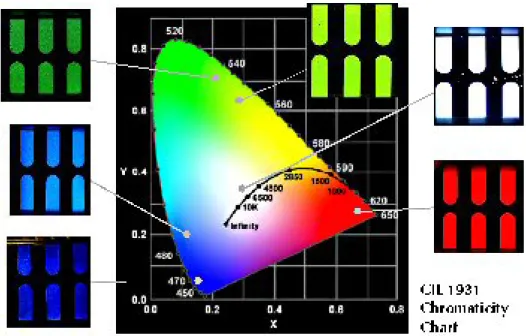
Figure 1. PLEDs can be used to provide different color. (adapted from
http://www.cdtltd.co.uk/technology/37.asp) ...25
Figure 2. (a) Typical absorption, photo- and electroluminescence spectra of PPV.[34] (b) Cyclic voltammetry of dialkoxy-PPV. [35] ...25
Figure 3. Polymers with phenyl derivatives in the backbones...26
Figure 4. Schematic representation of single-layer OLED ...26
Figure 5. The mechanism of Light-emitting process ...27
Figure 6. The structure of Polyfluorene (PFs). ...27
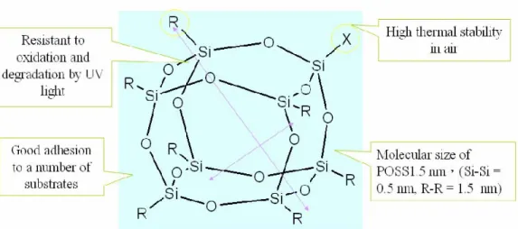
Figure 7. The structure of Polyhedral Oligomeric Silsesquioxane (POSS) ...28
Figure 8. TEM micrographs and photoluminescence spectra of PPV-quantum dot composites. In each of the three photoluminescence profiles, the blue curve is solution photoluminescence and the red curve is solid-state photoluminescence. (a) 1-Functionalized CdSe nanocrystals blended with PPV (b) pyridine-covered CdSe nanocrystals blended with PPV and (c) composite CdSe nanocrystal-PPV, where PPV was grown from the nanocrystal surface. (adapted from J. AM. CHEM. SOC. 2004, 126, 11322) ...28
Chapter 2: Polyfluorenes Incorporating Side-Chain-Tethered Polyhedral Oligomeric Silsesquioxane Units Figure 1. 1H NMR spectra of (a) 3, (b) Cl-POSS, and (c) 4. ...43
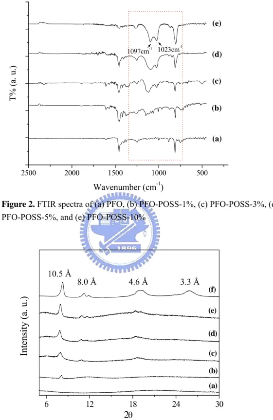
Figure 2. FTIR spectra of (a) PFO, (b) PFO-POSS-1%, (c) PFO-POSS-3%, (d) PFO-POSS-5%, and (e) PFO-POSS-10%. ...44
Figure 3. X-Ray diffraction curves of PFO-POSS nanocomposite films. (a) PFO, (b) PFO-POSS-1%, (c) PFO-POSS-3%, (d) PFO-POSS-5%, (e) PFO-POSS-10%, and (f) pure Cl-POSS. ...44
at 200 °C for 1 h (dashed line) and 2 h (solid line) under a nitrogen atmosphere. (b) FTIR spectra of (i) PFO, (ii) PFO-POSS-5%, and (iii) PFO-POSS-10% before (solid line) and after (dashed line) baking at 200 °C for 6 h. ...45
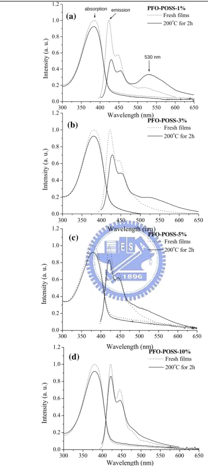
Figure 5. UV–Vis absorption and PL spectra of (a) PFO-POSS-1% , (b)
PFO-POSS-3%, (c) PFO-POSS-5%, and (d) PFO-POSS-10% films before (dotted line) and after (solid line) annealing at 200 °C for 2 h under a nitrogen atmosphere...46
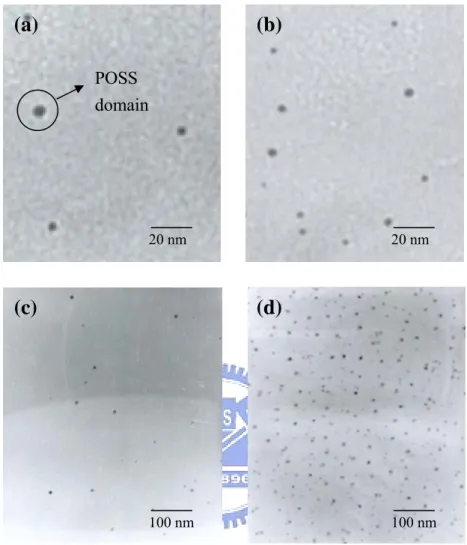
Figure 6. Transmission electron micrographs of (a) PFO-POSS-1%, (b)
PFO-POSS-3%, (c) PFO-POSS-5%, and (d) PFO-POSS-10%...47
Figure 7. Electroluminescence spectra of the devices prepared from PFO-POSS and
PFO in the configuration ITO/PEDOT/polymer/Ca/Al. ...48
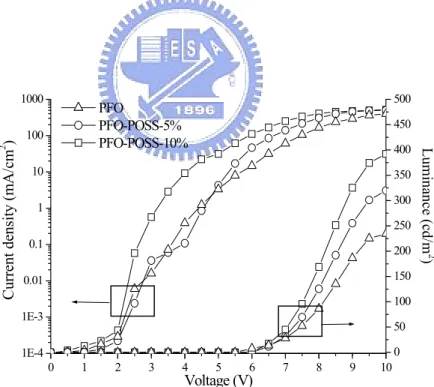
Figure 8. I–V curves of the devices prepared from PFO-POSS and PFO in the
configuration ITO/PEDOT/polymer/Ca/Al. ...48
Figure 9. UV-vis absorption and Photoluminescence spectrum (excited at 380 nm) in
THF of (a) PFO, (b) PFO-POSS-1%, (c) PFO-POSS-3%, (d) PFO-POSS-5%, (e) PFO-POSS-10%...49
Figure 10. TGA curves of polymer at a heating rate of 20 oC/min under nitrogen
atmosphere. (a) DSC curves of PFO and PF-POSS-10% at a heating rate of 10 o
C /min under nitrogen atmosphere. ...49
Chapter 3: Polyphenylenevinylene Copolymer Presenting Side-Chain-Tethered Silsesquioxane Units
Figure 1. 1H NMR spectra of (a) Cl-POSS, (b) POSS-CH3, and (c) POSS-CH2Br. .. ...62
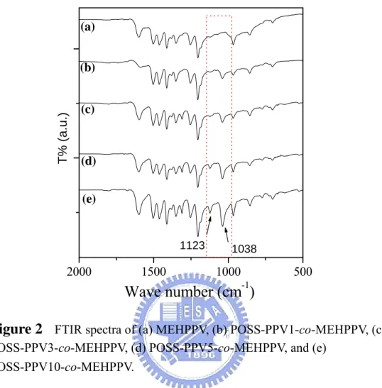
Figure 2. FTIR spectra of (a) MEHPPV, (b) POSS-PPV1-co-MEHPPV, (c)
POSS-PPV3-co-MEHPPV, (d) POSS-PPV5-co-MEHPPV, and (e)
POSS-PPV10-co-MEHPPV. ...63
Figure 3A. UV–Vis absorption and PL spectra of (a) MEHPPV, (b)
POSS-PPV1-co-MEHPPV, (c) POSS-PPV3-co-MEHPPV, (d)
state. ...64
Figure 3B. Normalized (relative to their maximum wavelengths) PL spectra of (a)
MEHPPV and (b) POSS-PPV10-co-MEHPPV annealed at room temperature and 150oC in the solid state. ...64
Figure 3C. X-ray diffraction spectra of (a) MEHPPV, (b) POSS-PPV1-co-MEHPPV,
(c) POSS-PPV3-co-MEHPPV, (d) POSS-PPV5-co-MEHPPV, (e)
POSS-PPV10-co-MEHPPV, and (f) Cl-POSS. ...65
Figure 3D. Deconvoluted X-ray diffraction spectra of (a) MEHPPV and (b)
POSS-PPV10-co-MEHPPV. ...65
Figure 4A. (a) Transmission electron micrograph of POSS-PPV10-co-MEHPPV. (b)
enlarged view. (c) EDS of POSS-PPV10-co-MEHPPV. ...66
Figure 4B. Surface roughness of thin films of (a) MEHPPV. (b)
POSS-PPV10-co-MEHPPV. ...67
Figure 5. Electroluminescence spectra of the devices prepared from
POSS-PPV-co-MEHPPV in the configuration ITO/PEDOT/polymer/Ca/Al. ...68
Figure 6. I–L-V curves of the devices prepared from POSS-PPV-co-MEHPPV and
MEHPPV in the configuration ITO/PEDOT/polymer/Ca/Al. ...68
Figure7. UV–Vis absorption and PL spectra of (a) MEHPPV, (b) POSS-PPV1-co-
MEHPPV, (c) POSS-PPV3-co-MEHPPV, (d) POSS-PPV5-co-MEHPPV, and (e) POSS-PPV10-co-MEHPPV recorded in THF solution. ...69
Figure 8. DSC traces of (a) MEHPPV, (b) POSS-PPV1-co-MEHPPV, (c)
POSS-PPV3-co-MEHPPV, (d) POSS-PPV5-co-MEHPPV, and (e)
POSS-PPV10-co-MEHPPV. ...69
Figure 9. TGA traces of (a) MEHPPV, (b) POSS-PPV1-co-MEHPPV, (c)
POSS-PPV3 -co-MEHPPV, (d) POSS-PPV5-co-MEHPPV, and (e)
POSS-PPV10-co-MEHPPV. ...70
Chapter 4: Thiophenol-modified CdS nanoparticles enhance the luminescence of benzoxyl dendron-substituted polyfluorene copolymers
Figure 1. Normalized UV–Vis absorption spectra recorded in DMF for S-CdS
nanoparticles having three different diameters. ...84
Figure 2. (a) Photoluminescence spectra of PF [poly-2,7-(9,9-dioctylfluorene)],
excited by a xenon lamp at λmax = 393 nm, and PF-G0, PF-G1, and PF-G2, all recorded in THF at the same concentration (5 × 10⁻⁶ M). (b) Photoluminescence spectra recorded in DMF of (i) PF-G1 in the solid state, using a xenon lamp as the excitation light source, (ii) PF-G1 in the solid state, using a GaN diode laser, and (iii) S-CdS nanoparticles having three different diameters. ...85
Figure 3. Photoluminescence spectra of thin films of (a) S-CdS3nm/PF-G1, (b) S-CdS4nm/PF-G1, and (c) S-CdS7nm/PF-G1, normalized with respect to the PL intensity of PF-G1. ...86
Figure 4. Photoluminescence spectra of thin films of (a) pure PF-G0, (b) PF-G0
containing 4 wt% S-CdS, (c) pure MEHPPV, (d) MEHPPV containing 4 wt% S-CdS, and (e) PMMA containing 4 wt% S-CdS. ...87
Figure 5. A. X-ray diffraction spectra of S-CdS/ PF-G1 nanocomposite. (a) PF-G1
(b) PF-G1 containing 3 wt% S-CdS, (c) PF-G1 containing 4 wt% S-CdS, and (d) PF-G1 containing 8 wt% S-CdS. B. The effect of the amount of S-CdS on the Bragg d spacing of PF-G1. C. FTIR spectra of (a) PF-G1 and (b) PF-G1 containing 4 wt% S-CdS. D. Cyclic voltammogram of the oxidation of polymer. ...88
Figure 6. Transmission electron microscopy images of PF-G1 films containing (a) 3
wt% and (b) 4 wt% of S-CdS. ...90
Figure 7. Normalized electroluminescence spectra of devices prepared from
S-CdS/PF-G1 in the configuration ITO/PEDOT/polymer/Ca/Al. ...90
Figure 8. (a) I–V and (b) L–V curves of devices prepared from S-CdS/PF-G1 in the
configuration ITO/PEDOT/polymer/Ca/Al. ...91
Chapter 5: Polyfluorene Copolymer Incorporating Side-Chain-Tethered Gold Nanoparticles
Figure 2. XPS spectra [S(2P) region] of PF-DBMS adsorbed onto Au NPs. ...103 Figure 3. Normalized UV–Vis absorption spectra and PL emission spectra of
PF-DBMS recorded in solution (THF) and from a thin film. The inset displays the thin film after thermal treatment at 100oC for 2 h. ...103
Figure 4. (a) Transmission electron microscopy images of Au/PF-DBMS films. The
inset displays the lattice image (lattice spacing: ca. 2.3Å) of the Au NPs. (b) Size distribution of Au NPs in the PF-DBMS polymer matrix. (c) TEM images of cross-sections of the device. ...104
Figure 5. (a) I–V and (b) L–V curves of devices prepared from Au/PF-DBMS in the
configuration ITO/PEDOT/polymer/Ca/LiF/Al. ...105
Figure 6. EL spectra of devices prepared from Au/PF-DBMS in the configuration
ITO/PEDOT/polymer/LiF/Ca/Al. ...106
Figure 7. (a) 1H NMR spectra of the chemical structure of all polymers. (b) The
Scheme & Table Lists
Chapter 1: Introduction
Scheme 1. (a) The Wessling-Zimmerman precursor route to PPV. (b) End-capping
modification of the Gilch polymerization. ...24
Chapter 2. Polyfluorenes Incorporating Side-Chain-Tethered Polyhedral Oligomeric Silsesquioxane Units Scheme 1. Synthesis of D-POSS-diAF (4) (i) CrO3, acetic anhydride, HCl(aq). (ii) aniline, aniline hydrochloride. (iii) K2CO3, KI, DMF/THF (5:4) ...40
Scheme 2. Synthesis of PFO-POSS copolymers ...41
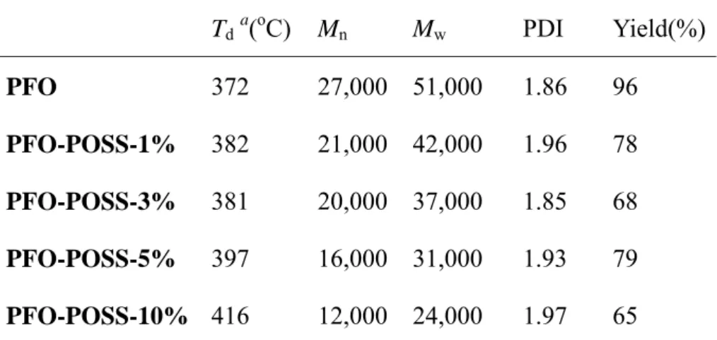
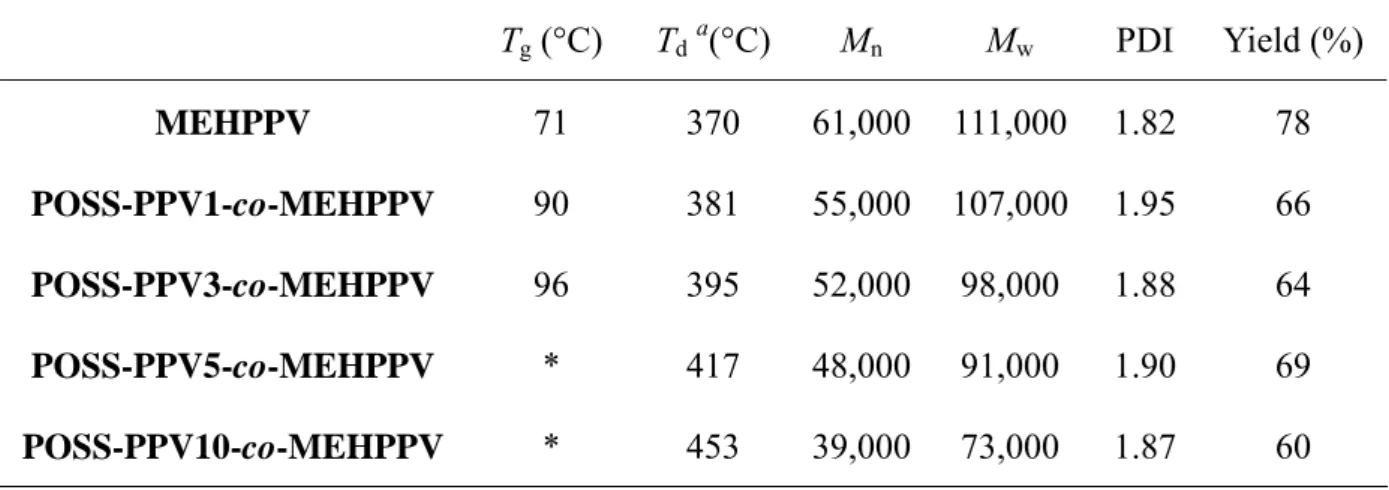
Table 1. Physical properties of the PFO-POSS copolymers ...42
Table 2. Optical properties of the PFO-POSS nanocomposites. ...42
Chapter 3: Polyphenylenevinylene Copolymer Presenting Side-Chain-Tethered Silsesquioxane Units Table 1. Physical Properties of the POSS-PPV-co-MEHPPV Copolymers. ...60
Table 2. Optical Properties of the POSS-PPV-co-MEHPPV Nanocomposites. ...60
Scheme 1. Synthesis of POSS-PPV-co-MEHPPV copolymers. Reagents and conditions: i, trichloro[4-(chloromethyl)phenyl]silane, HNEt3Cl; ii, K2CO3, DMF/THF; iii, N-bromosuccinimide (NBS)/ AIBN/ CCl4; iv, tert-BuOK/ THF. ..61
Chapter 4: Thiophenol-modified CdS nanoparticles enhance the luminescence of benzoxyl dendron-substituted polyfluorene copolymers Scheme 1. Synthesis of (a) S-CdS and (b) PF-GX and (c) a schematic drawing of the architecture of S-CdS/PF-GX (X = 1, 2). ...82
Table 1. Absorption and photoluminescence data for S-CdS/polymer nanocomposites in the solid state. ...83
Table 2. Thermal behavior of S-CdS/polymer nanocomposites. ...83
Chapter 5: Polyfluorene Copolymer Incorporating Side-Chain-Tethered Gold Nanoparticles
Table 1. Absorptions and Quantum Yields for Au NP/Polymer Nanocomposite Solid
Films. ...100
Table 2. Absorptions and Quantum Yields for Polymer Solid Films. ...100 Table 3. Molecular Weights of the Polymers. ...101 Scheme 1. Synthesis of (a) PF-DBMS copolymers (b) A schematic drawing of the
The list of abbreviations
BuLi n-butyllithium
CDT Cambridge Display Technology
CdS Cadmium Sulfide
DMF N,N-dimethylformami
DSC differential scanning calorimetry FWHM full width at half maximum, [nm]
GPC gel-permeating chromatography
HOMO highest occupied molecular orbital
HTL hole-transport layer
ITO indium tin oxide
MEH-PPV poly[2-methoxy-5-(2-ethylhexyloxy)-p-phenylene vinylene] S-CdS Thiophenol-modified cadmium sulfide
PDI polydispersity index
PEDOT poly(3,4-ethylenedioxythiophene) PF polyfluorene PFO poly(9,9-dioctylfluorene) PF-DBMS poly{2,7-(9,9´-dioctylfluorene)-co-4-diphenylamino-4´-bipen ylmethylsulfide} PL photoluminescence
PLED polymeric light emitting diode
PMMA poly(methyl methacrylate)
POSS polyhedral oligomeric silsesquioxane
PPP poly(p-phenylene)
PPV poly(p-phenylene vinylene)
PT polythiophene
Q.E. quantum efficiency
Tg glass transition temperature TGA thermal gravimetric analysis
THF tetrahydrofuran
ΦPL quantum yield of photoluminescence XPS X-ray photoelectron spectroscopy
Abstract
The main objective of this dissertation is to study the performance of polymer light emitting diodes involving luminescent polymers incorporating different kinds of inorganic segment in their side chains. In the introduction of this dissertation, we gave an explanation on the historical evolution of polymer nanocomposites light emitting diodes and summarized the literatures in the recent years. In the chapter 2, we have synthesized polyhedral silsesquioxane-tethered polyfluorene copolymers, poly(9,9´-dioctylfluorene-co-9,9´-bis[4-(N,N-dipolysilsesquioxane)
aminophenyl]fluorene) (PFO-POSS), that have well-defined architectures using Suzuki polycondensation. This particular PFO-POSS molecular architecture increases the quantum yield of polyfluorene significantly by reducing the degree of interchain aggregation; in addition, these copolymers exhibit a purer and stronger blue light by preventing the formation of keto defects. The PPV-POSS molecular architecture also increases the quantum yield significantly by reducing the degree of interchain aggregation were discussed in Chapter 3. This particular molecular architecture of POSS-PPV-co-MEHPPV copolymers possesses not only a larger quantum yield (0.85 vs. 0.19) but also higher degradation and glass transition temperatures relative to those of pure MEHPPV. The maximum brightness of a double-layered-configured light emitting diode (ITO/PEDOT/emissive polymer/Ca/Al) incorporating a copolymer of MEHPPV and 10 mol% PPV-POSS was five times as large as that of a similar light emitting diode incorporating pure MEHPPV (2196 vs. 473 cd/m2).
The presence of a low percentage of thiophenol-modified cadmium sulfide
substantially improves the efficiency of its light emission were discussed in Chapter 3. The enhancements in photoluminescence and electroluminescence arise mainly from a reduction in the degree of energy transfer from the excited polymer chains to their neighboring polymer chains in the ground state; i.e., there is an increase in the
inter-polymer chain distance when CdS nanoparticles are present. We have prepared highly luminescent dendron-substituted copolyfluorenes that incorporate
surface-modified cadmium sulfide nanoparticles. A small percentage of these nanoparticles can be incorporated into the dendritic structures upon tailoring the interfaces between the ligands on the nanoparticles and the dendritic structures in the copolyfluorene. Both the photoluminescence and electroluminescence efficiencies of the polymer nanocomposites are dramatically enhanced. Moreover, in order to know the effect to some other nanoparticles, we have tethered gold nanoparticles (Au NPs) to the side chains of poly{2,7-(9,9´-dioctylfluorene)-co- 4-diphenylamino-4´- bipenylmethylsulfide} (PF-DBMS) through its ArSCH3 anchor groups. The presence of 1 wt% of the tethered gold NPs led to a reduction in the degree of
aggregation of the polymer chains, resulting in a 50% increase in its quantum yield. The electroluminescence of a 1wt% Au/ PF-DBMS device was three times higher in terms of its maximum brightness and its full-width-at-half-maximum emission peak was much narrower than that of a pure PF-DBMS device. These phenomena arise from the photooxidation suppression, hole blocking, and electron transport enhancing effects of the Au NPs were also demonstrated in Chapter 5.
摘要
高分子發光二極體(PLED)是未來發展成大平面的顯示器的重要技術,而大部 份的電激發光高分子,由於具有豐富的π電子,因此電洞注入特性和傳輸電洞的 能力遠比電子注入特性和傳輸電子的能力來的有效率。 近期不少研究著重於開 發高效率且穩定的發光材料,其中又以藍光材料最受重視。 聚茀(Polyfluorene) 及其衍生物由於包含一剛性且共平面的雙苯環結構,所以表現出特殊的物理和化 學性質; 然而,無論是PPV 或者是PF系列元件在製成薄膜時,由於材料累積濃 度過高造成分子堆疊或產生excimer,嚴重影響光色以及降低發光效率; 此外,PF 系列由於C9位置容易產生氧化現象(keto defect),也會改變元件原有穩定的發光 光色。 為了改善這些缺點,選擇導入多立面體聚矽氧烷(POSS) 於高分子材料之 側鏈期望以防止氧化及減少分子堆疊,使得高分子的光色及熱穩定性進一步改 良,可廣泛地應用在顯示器的發光材料上。此方法所合成之高分子奈米複合材料 可提升發光高分子之發光效率、元件效率並提升其耐熱度及穩定性。 在本文的 第二及第三章節,我們將分別討論POSS在Polyfluorene(PF) 與 Polyphenyl vinylene (PPV)中所扮演的角色。 另外一部分,有鑒於高分子內部螢光發光效 率最高僅達25%的物理限制,高分子與無機材料的結合便受到了矚目﹔雖近期有 磷光高分子發光二極體之開發,但合成時必須使用重金屬,來源恐不穩定。因此, 本研究嘗試以膠體化學法合成半導體材料量子點 (其直徑小於10 奈米)製備一 系列S-CdS/PF-GX (X=1, 2)之奈米複合發光材料,並藉由實驗證實,導入少量改 質的量子點(S-CdS),不但可有效地提昇螢光及電激發光效率至原來之兩倍至三 倍,同時也增強原本材料在製程元件後的穩定度及電性。在第五章中我們選擇用 金奈米粒子並對其特性作進一步的探討。含有1wt %的金奈米粒子之聚茀高分子 共聚物提高了原本的量子效率與光學穩定性;同時在元件部份,與純聚茀高分子 共聚物比較,高分子藉由鍵結金奈米粒子之元件也具有較優異的表現。
Chapter 1
Chapter 1: Introduction
1-1 Introduction of Light Emitting Polymer and History
Since the discovery of PLEDs in 1989[1], significant effort has been directed into the development of red, green and blue materials that exhibit high efficiency and stability under normal operating conditions, and to enable integration into flat panel display (FPD) applications (Figure 1). From 1989 until now, LEDs is probably the most important application maintaining the researchers’ interest towards conjugated (conducting) polymers, although in recent years we witness a growing interest towards other relevant applications such as sensors and photovoltaics. Hundreds of academic research groups around the worlds have contributed to the development of electroluminescent polymers. An even more pronounced research activity is being held in industry. Several newly born R&D companies such as Cambridge Display Technologies (CDT, spin-off from Cambridge University), Covion Organic
Semiconductors and UNIAX (spin-off from UCSB), are targeted at development of high efficiency, long life-time EL polymers. A huge commercial potential, connected with the possibility of solution fabrication of EL devices, and, particularly, flat and/or flexible displays, attracted in the business such industrial giants as Dow Chemical, DuPont, IBM, Kodak and Philips. [2] PLEDs utilize the same physic principles as LEDs but use polymers as the active light-emitting layer. It has many
advantages when compared to normal inorganic LEDs. Simple and costefficient manufacturing and the ability to generate a uniform area of light demonstrate that PLEDs exhibit excellent promise for current and future electronic and optical applications. The first PLEDs used poly(phenylene vinylene) PPV as the emitting layer. PPV is an undoped conjugated polymer, which has a molecular structure given
Chapter 1
in Figure 2. Today many other polymers such as polythiopenes, polypyridine, poly(pyridyl vinylenes) and polyphenylene have been used to emit light (Figure 3). Light emitting diodes consist of active or emitting layers placed between a cathode (typically aluminum or calcium) and an anode (ITO, indium tin oxide). A diagram of a typical PLED is shown in Figure 4. When the two electrodes are connected electrons are injected from the cathode into the p* -band semiconducting polymer and holes are injected from an electrode into the p –band. The oppositely charged carriers in the two bands meet within the polymer films and recombine (return to their ground state) radiatively to give off light. [3] (Figure 5)
1-2 Research Motivation
1-2-1. The Original of Green Emission in Polyfluorene-based Conjugated Polymers: On-Chain defect Fluorescence.
Conjugated polymers have been studied in great detail as electroluminescent materials for use in organic light emitting diodes. Significant progress has been made in understanding the fundamental working processes involved in generating efficient, reliable light across the entire visible spectrum. Polyfluorene-based materials have been investigated extensively because of the many attractive properties they possess. Additional experimental results are needed to discern the nature of the unwanted green emission that often appears during device operation and quantum efficiencies need to be significantly improved. The currently most challenging topic for conjugated polymers applications is blue emission color stability. All available poly(para-phenylene) (PP)-type materials, which are the most promising family of
Chapter 1
blue light emitters, are prone to degradation, resulting in an unwanted change in color due to the emergence of low energy green emission peak. However, vital to overcome the problem and to provide sutible future synthetic stragies. The low-energy
emission band has been mostly attributed to recordering of the polymer chains and subsequent aggregate[4] or excimer formation.[5] It will be shown in the following that both excimer and aggregate formation cannot explain the presented experimental observations and can therefore be ruled out as the main origins of the energy emission band of polyfluorene-type polymers as suggested previously. [6] Instead, the
experimental observations show fluorescence from an on-chain oxidative defect to be the source of this emission band.
1-2-2. keto defect
Low-energy emission bands have been identified in all PPP-type polymers upon thermal, [7] photo-, and/ or electrical degradation. Recently, the occurrence of this emission band has been correlated to presence of ketonic defects incorporated into the polymer backbone in the form of 9-fluorenones. Furthermore, fluorene-fluorenone copolymers has established a quantitative correlation between the 9-fluorenone content and the low-energy emission band intensity. However, no unambiguous verdict about the nature of the emission (emission from the aggregation or excimer) could be found. This identification is, however, crucial for determining future synthetic approaches: Influencing the solid state packing of the polymer chains by bulky side chains, [8] spiro-linked compounds, [9] or disorder induced by the
copolymerization of fluorine with e.g., anthracene[10] could effectively hinder aggregate or excimer formation. Fluorescence emission from oxidative (on-chain) defects, on the contrary, can only be excluded by improving the oxidative stability of
Chapter 1
the polymers.
1-2-3. Luminescence Enhancement in Polymer/Nanoparticle Composite Electro-Optic Devices
Polymer light emitting diodes have a good chance to become the main display system in the near future since diodes have many advantages concerning preparation and operation over other display systems. However, material with single species often can not meet all the stringent criteria of industrial applications. The major drawbacks of the PLEDs have been operating life times and insufficient device radiances. Recently, it has been shown that incorporating oxide nanoparticles into a PPV
derivative enhances the PLED current density and radiance by an order of magnitude. In this thesis, we have to improve or tailor material properties with composite and develop finely tailored nanocomposite materials for emissive or non emissive display technology. An efficient way to obtain promising new materials is to modify existing potential materials with doping of semiconductor nanoparticles are described.
1-3 Materials
1-3-1. Polyfluorene (PF)
Fluorene is a polycyclic aromatic compound, which received its name due to strong violet fluorescence which arises from highly conjugated planar π-electron system. The 2,7-Positions in fluorene are the most reactive sites towards
electrophilic attack, which allows construction of a fully conjugated rigid-rod polymer chain by substitution reactions, whereas the methylene bridge provides an opportunity
Chapter 1
to modify the processability of the polymer by substituents, without perturbing the electronic structure of the backbone. The varieties, excellent optical and electronic properties, and high thermal and chemical stability of polyfluorenes (PFs) make them an attractive class of materials for polymer light-emitting diodes (PLEDs). Different aspects of syntheses, properties and LED applications of fluorene-based conjugated polymers and co-polymers have been highlighted in several recent reviews. [11] In fact, polyfluorenes are the only class of conjugated polymers that can emit a whole range of visible colors with relatively high quantum efficiency.
It is well known that PFs are the most promising class of blue-emitting materials. The original problem associated with undesirable “green emission band” was shown to be a result of exciton trapping on the electron deficient fluorenone defect sites. The color purity can be reestablished via 1) careful purification of the monomer (complete elimination of mono-substituted units), 2) inserting a protecting layer between the PF and reactive cathode material, 3) introducing hole-trapping sites (most commonly, triarylamine units), which would compete with fluorenone defects, minimizing the excitone formation on the latter, 4) introducing bulky substituents into PF backbone, which would minimize the exciton trapping on fluorenone defects. Furthermore, introducing of different conjugated moieties into PF backbone allows for efficient color tuing in these materials.
1-3-2. Poly(p-phenylene vinylene) PPV
Conjugated polymers are organic semiconductors in which the п-molecular orbitals are delocalized along the polymer backbone. Polymer-based OLEDs are attractive due to their excellent film forming properties and their ease of application
Chapter 1
over large surfaces through simple, economically viable coating techniques such as spin coating or ink-jet printing. Small molecule emissive materials are typically coated as thin films via vacuum-deposition which is difficult over large areas and is not as cost effective. As previously stated, PPV was the first polymer that was shown to display electroluminescence. Since direct synthesis of PPV produces an insoluble material, an alternative route was developed to allow the spin-coating of a soluble precursor polymer from solution (Scheme 1). Poly(p-phenylene vinylene) (PPV) is a highly stable conjugated polymer. Its yellow color is due to an absorption band centered at ~400–420 nm (depending on the method of synthesis) with an on-set corresponding to a band gap of ~2.5 eV.[12] The HOMO and LUMO levels in PPV can be accessed in cyclic voltammetry experiments, which, under proper conditions, reveal chemically reversible oxidation and reductions waves (Figure 2a). The deduced electrochemical gap corresponds reasonably well to the optical band gap. There are number of synthetic strategies elaborated for preparation of PPV homo- and
co-polymers: [13]
1. Thermoconversion (Wessling-Zimmerman route) 2. Chemical vapor deposition (CVD)
3. Ring-opening metathesis polymerization (ROMP) 4. The Gilch polycondensation
5. Chlorine precursor route (ROMP) (Gilch modification) 6. Non-ionic route (Gilch modification)
7. Knoevenagel polycondensation 8. Heck coupling polymerization 9. Wittig(-Horner) Condensation 10. Miscellaneous.
Chapter 1
Being a relatively good electron donor, PPV and its derivatives can be chemically doped by strong oxidating agents and strong acids, affording highly conductive p-doped materials (with conductivity up to ~104S/cm5). The yellow-green fluorescence of PPV is featured by a vibronically structured emission band with peaks maxima at 520 and 551 nm (Figure 2b).
1-3-3. Polyhedral Oligomeric Silsesquioxanes (POSS)
Organic-inorganic nanocomposites with well-defined architectures have attracted a great deal of attention since they not only have synergistic properties, but can also be tailored to specific technical applications[14]. One class of inorganic component- polyhedral oligomeric silsesquioxanes (POSS) has nanometer-sized structure with high surface area and controlled porosity has been demonstrated to an efficient method in the design of hybrid materials[15-27]. POSS has two unique features : (1) the chemical composition is a hybrid, intermediate (RSiO1.5) between that of silica (SiO2) and silicones (R2SiO). (2) POSS molecules are physically large, POSS consists of a rigid, cubic silica core with a 0.53 nanometer side length and can have organic functional groups connected to the vertices of the cubic core for further reaction (Figure 7). Due to its versatile functional groups and high solubility in several solvents, POSS molecules can form covalent bonds with themselves or organic monomers. POSS molecules are typically stable up to 400oC, which are higher than the thermal degradation temperatures of most polymers. Their
incorporation into some polymers has lead to enhancements in thermal stability and mechanical properties. For instance, POSS molecules have been successfully incorporated into acrylics[15], styryls[16], epoxy[17] and polyethylene[24].
Chapter 1
1-3-4. Nanoparticles
One of the most interesting subjects in materials science is a quantum confinement effect in low-dimensional systems as quantum wells, quantum wires, and quantum dots. Nanoparticles play an important role for nanotechnology and livelihood applications, for example catalysts, light-emitting diode, etc. Recently, many kinds of metal, metal oxide or semiconductor nanoparticles were reported for applications, such as Au or CdSe nanoparticles for bio-labeling and solar devices, TiO2
nanoparticles for photo-catalysis materials, Co, CoFe O and Fe O2 4 2 3 nanoparticles for magnetic applications. For semiconductor nanoparticles with sizes close to their Bohr exciton radius (typically between 1-10 nm), the size-dependent band gap results in tunable optical properties. These semiconductor nanoparticles are termed as quantum dots because their tunable optical properties can be predicted by quantum mechanics. Among these studies, quantum confined semiconductor nanoparticles, such as CdS and CdSe/ZnS, are highly potential to light emitting diode devices.
1-3-5. Nanoparticle Applications in PLEDs
The potential use of polymer light-emitting diodes is ultimately limited by their low quantum efficiency as well as by their poor stability due to oxygen. A recent study found that blending Au NPs with polyfluorene resulted in enhanced luminescent stability. [28] Blue polymer light-emitting diodes with enhanced luminescent
stability were obtained by incorporating 5-10 nm gold nanoparticles as the quenchers of the triplet states of blue emitting polymer. The nanocomposite light-emitting diodes exhibited an enhanced quantum efficiency due to the roughening of the surface onto which the Al cathode is deposited and to balanced charge injection.
Chapter 1
nanoparticles carries advantages over cases where nanoparticle aggregation dominates. Such dispersion has been particularly difficult to obtain in the case of composites prepared from nanoparticles and conjugated polymers. One recent study found that cadmium selenide nanocrystals, or quantum dots, can be integrated into thin films of poly( paraphenylene vinylene) (PPV) without aggregation. [29] (Figure 8) The ability to tailor and disperse quantum dots in PPV thin films in this fashion dramatically impacts the photophysical properties of these materials relative to conventional blends. While PPV coverage is emphasized here, the novel quantum dot growth methods, and the general polymerization methodology, carry the potential for broad applicability that will enable new physical studies and device fabrication using polymer-quantum dot composite materials.
Chapter 1
(a)
(b)
Scheme 1. (a) The Wessling-Zimmerman precursor route to PPV. (b) End-capping
Chapter 1
Figure 1. PLEDs can be used to provide different color. (adapted from
http://www.cdtltd.co.uk/technology/37.asp)
(b)
(a)
Figure 2. (a) Typical absorption, photo- and electroluminescence spectra of PPV.[34]
Chapter 1
Figure 3. Polymers with phenyl derivatives in the backbones.
Chapter 1
Figure 5.
The mechanism of Light-emitting process.
Chapter 1
Figure 7.
The structure of Polyhedral Oligomeric Silsesquioxane (POSS).Figure 8.
TEM micrographs and photoluminescence spectra of PPV-quantum dot composites. In each of the three photoluminescence profiles, the blue curve is solution photoluminescence and the red curve is solid-state photoluminescence. (a) 1-Functionalized CdSe nanocrystals blended with PPV (b) pyridine-covered CdSe nanocrystals blended with PPV and (c) composite CdSe nanocrystal-PPV, where PPV was grown from the nanocrystal surface. (adapted from J. AM. CHEM. SOC. 2004, 126, 11322)
Chapter 2
Chapter 2: Polyfluorenes Incorporating Side-Chain-Tethered
Polyhedral Oligomeric Silsesquioxane Units
2-1 Introduction Materials
Semiconducting polymers have been studied extensively for their potential applications in electroluminescent displays, [32] solar cells, [33] and thin film organic transistors. [34] One of the most promising conjugated polymers is polyfluorene, which has been applied widely for its characteristic of emitting blue light. [35-38]
Polyfluorenes may be functionalized readily by modifying the C-9 position of the fluorene monomer; such modification can, for instance, provide good solubility in common organic solvents that allows further processing. In the solid state, polyfluorene and its derivatives exhibit adequate photoluminescence (PL) and electroluminescence (EL) efficiencies. [8, 39–40] The application of polyfluorenes in light emitting diodes, however, has been hampered by the appearance of green
electroluminescence (ca. 530 nm) in addition to the desired peak at 425 nm; this green electroluminescence has been attributed to either intermolecular interactions, which lead to the formation of aggregates, [41–47] or to the presence of emissive keto defect sites that arise as a result of thermo- or electro-oxidative degradation of the
polyfluorene backbone. [48] A detailed discussion of this phenomenon has been presented elsewhere. [48b] As a result, the expected blue emission from polyfluorene becomes an undesired blue-green color in LED applications.
Several approaches have been adopted to reduce the formation of aggregation or keto defect in polyfluorenes, including the introduction of bulky side chains, using cross-linkedstructures, improving the oxidative stability of pendant groups or chain ends, [45] and limiting chain mobility by blending it with a high-Tg polymer. [47] One
Chapter 2
of the most recent approaches involves incorporation of polyhedral oligomeric silsesquioxane (POSS) into the conjugated polymer. The first such study was undertaken by attaching POSS covalently to the chain ends of
poly(2-methoxy-5-[2-ethylhexyloxy]-1,4-phenylenevinylene) (MEHPPV) and poly(9,9´-dioctylfluorene) (PFO), which resulted in enhanced thermal stability of the devices prepared from these modified polymers.[45] The density of the polymer chain ends, however, decreases as the molecular weight of the polymer increases, which limits the amount of POSS that can be attached (ca. 1.2%). Another study involved a synthesis of a bridged polyfluorene copolymer by using fluorene
tetrabromide monomers featuring a siloxane bridge. The thermal stability of a device made from this siloxane-bridged polyfluorene appears to be better than that prepared from pure PFO. [48] A third related study involved attaching polyfluorene to the functionalized vertices on the cubic polyhedral silsesquioxane core units to form starlike structures; these polymers possessed improved thermal and
optoelectronic characteristics. The amount of POSS content in the polyfluorene was ca. 3.8%. [48] The enhanced electroluminescence characteristics in these
polyfluorenes have been attributed to POSS imparting a reduction in either the degree of aggregation and excimer formation or the number of keto defects. The molecular architecture that polyfluorene possessed in the latter two studies cannot be defined easily. Previously, we synthesized a polyimide-side-chain-tethered POSS as an approach to lowering its dielectric constant. [49a] In this present study, we took a copolymer approach by synthesizing polyfluorene-tethered POSS in a well-defined architecture. To the best of our knowledge, the introduction of an inorganic side group, such as POSS, into the C-9 position of polyfluorene has not been explored previously. We believe that by developing a POSS/polyfluorene copolymer having well-defined architecture we will be able to tailor its luminescence properties more
Chapter 2
precisely by modifying the molecular structure. In this paper, we report the synthesis and characterization of fluorene-based random copolymers featuring tethered polyhedral oligomeric silsesquioxanes (POSS) units.
Scheme 1 displays the synthetic procedure we used to prepare the
POSS-dibromide monomer (D-POSS diAF), in which cyclopentyl-POSS was covalently bonded to the C-9 carbon atom of the fluorine unit through a
4-aminophenyl spacer. We used POSS-dibromide as a co-monomer, which, together with 2,7-dibromo-9,9´-dioctylfluorenone (5), were reacted with
2,7-bis(4,4,5,5-tetramethyl-1,3,2-dioxaborolan-2-yl)fluorene (6) through Suzuki coupling followed by end capping. Scheme 2 presents the complete synthetic procedure for the preparation of POSS-tethered polyfluorene. The extended 9,9´-bis(4-aminophenyl)fluorenyl core, which is readily accessible, offers the following additional advantages: (1) Direct attachment of the benzyl groups of POSS to the C-9 carbon atom of the fluorene unit is avoided; such benzyl linkages are potentially susceptible to photooxidation, which may cause degradation and failure of the polymer LEDs. [49b, 8] (2) The introduction of the 4-aminophenyl spacer reduces the steric hindrance imposed by POSS. [50] The insertion of a rigid phenylene spacer between the POSS side chain and the polymer backbone may lead to a shielding effect on the polyfluorene main chain, while leaving the reaction sites of the macromonomer accessible for the palladium-catalyzed polymerization reaction. (3) Through this copolymerization approach, the amount of POSS incorporated into the polyfluorene may be tuned by controlling the amount of POSS-dibromide monomer used in the polymerization.
Chapter 2
2-2-1. Materials
2,7-Dibromo-9,9´-dioctylfluorenone (5), [50] 2,7-bis(4,4,5,5-tetramethyl-1,3,2- dioxaborolan-2-yl)fluorene (6), [51] and the chlorobenzylcyclopentyl-POSS[52] were synthesized according to literature procedures. THF was distilled under nitrogen from sodium benzophenone ketyl; other solvents were dried using standard
procedures. All other reagents were used as received from commercial sources unless otherwise stated.
Chlorobenzylcyclopentyl-POSS. 1 H NMR (300 MHz, CDCl3): δ 7.64 (d, J = 8.1 Hz, 2H), 7.37 (d, J = 8.1 Hz, 2H), 4.57 (s, 2H), 2.26–1.21 (m, 56H), 1.16–0.81 (m, 7H) ppm. 29Si NMR (600 MHz, THF): δ –67.8, –68.2, –79.6 ppm.
Synthesis of 9,9´-Bis(4-aminophenyl)-2,7-dibromofluorene (3). A mixture of
2,7-dibromo-9-fluorenone (2) (3.0 g, 8.88 mmol), aniline (4.0 g, 4.30 mmol), and aniline hydrochloride (1.15 g, 8.88 mmol) was heated at 150 °C under nitrogen for 6 h. The reaction mixture was then slowly added into water (150 mL) and extracted with ethyl acetate (3 × 50 mL). The combined extracts were dried (MgSO4), the solvent was evaporated, and the residue was purified by column chromatography
(hexane/ethyl acetate, 4:1) to afford 3 (3.23 g, 72%). 1H NMR (CDCl3): δ 7.52 (d, J = 8.1 Hz, 2H), 7.44 (4H), 6.90 (d, J = 8.1 Hz, 4H), 6.53 (d, J = 8.1 Hz, 4H), 3.58 (s, 4H) ppm. Anal. Calcd for C25H18Br N2 2 (%): C, 59.31; H, 3.58; N, 5.53. Found: C, 59.38; H, 3.62; N, 5.47.
Chapter 2
(D-POSS-diAF) (4). 9,9-Bis(4-aminophenyl)-2,7-dibromofluorene (200 mg, 0.395
mmol) was stirred with K CO2 3 (764 mg, 5.53 mmol) and KI (262 mg, 1.58 mmol) in DMF (5 mL) and THF (4 mL) at room temperature for 1 h. A small amount of Cl-POSS (888 mg, 0.832 mmol) was added and then the whole mixture was heated at 70 °C for 3 h. The reaction mixture was then slowly poured into water (150 mL) and extracted with chloroform (3 × 30 mL). The combined extracts were dried (MgSO4), the solvents were evaporated, and the residue was purified by column chromatography (hexane/ chloroform, 1:10) to afford 4 (0.69 g, 68%). 1H NMR (CDCl3): δ 7.62-7.63 (m, 14H), 7.01-6.84 (m, 8H), 4.81 (s, 2H), 4.27 (s, 4H),
2.06–1.18 (m, 112H), 1.14–0.79 (m, 14H) ppm. Anal. Calcd for C109H154Br O2 24N Si2 16 (%): C, 52.67; H, 6.24; N, 1.13. Found: C, 52.11; H, 6.21; N, 1.07.
General Procedure for the Synthesis of Alternating Copolymers PFO-POSS.
Aqueous potassium carbonate (2 M) and aliquate 336 were added to a solution of the POSS-appended fluorene dibromide monomer 4, dibromide 5, and diboronate 6 in toluene. The mixture was degassed and purged with nitrogen three times. The catalyst, tetrakis(triphenylphosphine)palladium (3.0 mol%), was added in one portion under a nitrogen atmosphere. The solution was then heated at 90 °C and vigorously stirred under nitrogen for 5 days. End-group capping was performed by heating the solution under reflux for 6 h sequentially with phenylboronic acid and bromobenzene. After cooling, the polymer was recovered by precipitating it into a mixture of
methanol and acetone (4:1). The crude polymer was collected, purified twice by reprecipitation from THF into methanol, and subsequently dried under vacuum at 50 °C for 24 h. The 1H and C NMR spectra of PFO and PFO-POSS appear to be 13 identical because of the low content of POSS in the latter polymer.
Chapter 2
2-2-2. Characterization.
1H, C, and Si nuclear magnetic resonance (NMR) spectra of the compounds were 13 29 obtained using a Bruker DRX 300 MHz spectrometer. Mass spectra of the samples were obtained on a JEOL JMS-SX 102A spectrometer. Fourier transform infrared (FTIR) spectra of the synthesized materials were acquired using a Nicolet 360 FT-IR spectrometer. Gel permeation chromatographic analyses were performed on a Waters 410 Differential Refractometer and a Waters 600 controller (Waters Styragel Column). All GPC analyses of polymers in THF solutions were performed at a flow rate of 1 mL/min at 40 °C; the samples were calibrated using polystyrene standards. Thermogravimetric analysis (TGA) and differential scanning calorimetry (DSC) measurements were performed under a nitrogen atmosphere at heating rates of 20 and 10 °C/min, respectively, using Du Pont TGA-2950 and TA-2000 instruments,
respectively. UV–Vis absorption and photoluminescence (PL) spectra were recorded on a HP 8453 spectrophotometer and a Hitachi F-4500 luminescence spectrometer, respectively. Before investigating the thermal stability of the synthesized polymers, their polymer films were annealed in air at 200 °C for 2 h.
2-2-3. Device Fabrication and Testing.
The electroluminescent (EL) devices were fabricated on an ITO-coated glass substrate that was precleaned and then treated with oxygen plasma before use. A layer of poly(ethylene dioxythiophene):poly(styrene sulfonate) (PEDOT:PSS, Baytron P from Bayer Co.; ca. 40-nm thick) was formed by spin-coating from its aqueous solution (1.3 wt%). The EL layer was spin-coated at 1500 rpm from the corresponding toluene solution (15 mg mL–1) on top of the vacuum-dried PEDOT:PSS layer. The
Chapter 2
nominal thickness of the EL layer was 65 nm. Using a base pressure below 1 × 10⁻⁶ Torr, a layer of Ca (30 nm) was vacuum deposited as the cathode and a thick layer of Al was deposited subsequently as the protecting layer. The current–voltage
characteristics were measured using a Hewlett–Packard 4155B semiconductor parameter analyzer. The power of the EL emission was measured using a Newport 2835-C multi-function optical meter. The brightness was calculated using the forward output power and the EL spectra of the devices; a Lambertian distribution of the EL emission was assumed.
2-3 Results and Discussions
A. Polyphenylenevinylene Copolymer Presenting Side-Chain-Tethered Silsesquioxane Units Nanocomposites
Figure 1 displays the 1H NMR spectra of 9,9´-bis(4-aminophenyl)-2,7-dibromo -fluorene (3), Cl-POSS, and D-POSS-diAF (4). The peak for the NH protons shifted downfield from 3.59 ppm for 3 to 4.48 ppm for 4, while the CH2 peak of Cl-POSS shifted upfield from 4.47 to 4.21 ppm in D-POSS-diAF. The ratio of the peak areas of the benzylic CH2 and NH protons is ca. 2:1. Taken together, all of these data suggest that Cl-POSS had reacted with 4-aminophenyl fluorene to form
D-POSS-diAF. Table 1 lists the thermal properties and molecular weight
distributions of the PFO-POSS copolymers. Both the thermal degradation and glass transition temperature increased as the amount of POSS in PFO increased,
presumably because the tethered POSS enhanced the thermal stability and retarded the polymer chain mobility. The molecular weights of the PFO-POSS copolymers decreased upon increasing the POSS content; this phenomenon can be attributed to the steric hindrance caused by POSS during the polymerization process. Figure 2 displays FTIR spectra of PFO copolymers containing different amounts of POSS. The
Chapter 2
FTIR spectrum of POSS displays two major characteristic peaks in the range 1000–1180 cm–1 (Si–O–Si stretching). The Si–C band at 1074 cm–1, however, overlaps with the Si–O–Si band and, thus, could not be observed clearly.
Figure 3 displays the X-ray diffraction curves of Cl-POSS, PFO, and PFO-POSS. We observed no X-ray diffraction peaks for pure PFO. There are three distinct diffraction peaks at 2θ = 8.3, 19.1, and 26.1° observed for Cl-POSS (Fig. 3f), which correspond to d-spacings of 10.5, 4.6 and 3.3 Å, respectively. The d-spacing of 10.5 Å reflects the size of the Cl-POSS molecules; the other two spacings reflect the rhombohedral crystal structure of POSS molecules. [15] The presence of a small crystal peak of POSS in PFO indicates a mild degree of aggregation of POSS molecules. The DSC curves of pure PFO[53] indicate a value of Tg of 62 °C, a
crystallization exothermal peak (Tc) at 98 °C, and a melting endothermal peak (Tm) at 155 °C (see the Supporting Information). Only a small Tm at 166 °C appears in the curve for PFO-POSS-10%; the disappearance of the Tg and Tc peaks in this case (PFO containing 10% POSS) can be explained by the fact that the mobility of the PFO main chains, including chain folding, is severely retarded by the steric hindrance imposed by the bulky side-chain-tethered POSS units, as has been reported in the literature. [54] The UV–Vis and photoluminescence spectra of PFO and PFO-POSS recorded in THF are presented in the Supporting Information. Table 2 lists the wavelengths of the absorption and PL maxima and the quantum yields of PFO-POSS. The absorption and emission peak maxima of PFO occur at 384 and 418 nm, respectively; these values are close to those reported in the literature. [55] We observed no aggregation band in these spectra because THF is a good solvent for PFO. The absortion and emission peaks for PFO and PFO-POSS are almost identical. For each polymer, the absorption peak maximum in solution (THF) is located between 384 and 362 nm, with
Chapter 2
a slight blue shift caused by the presence of POSS; the PL maxima occur at similar wavelengths for all of the polymers. The quantum yields of the PFO-POSS
copolymers increased substantially as the amount of tethered POSS increased. In particular, the quantum yield of PFO containing 10% POSS was 54% higher than that of pure PFO (0.86 vs. 0.55). This finding can be attributed to the steric hindrance caused by the POSS units preventing aggregation of the PFO main chains, which, in turn, reduces the degree of dimer formation after excitation. This phenomenon is a result of the particular side-chain-tethered POSS architecture that we have employed: it has not been reported in previous studies of POSS/PFO copolymers. The other significant effect that the incorporation of the silsesquioxane into PFO side chain causes is the persistence of luminescence behaviour after thermal treatment of PFO-POSS. The stability of both color and luminescence at elevated temperatures are critical for polymer LEDs because sometimes the operating temperature of these devices exceeds 86 °C. Next, we investigated in detail the effect that thermal treatment has on POSS-incorporated PFO. Figure 4a displays the
photoluminescence spectra of PFO as a solid film after heat treatment at 200 °C; in all cases, the absorption peaks at 386 nm remain. Other than the main peak at 425 nm, we observe an additional small peak, at ca. 530 nm, in the spectrum of PFO film exposed at 200 °C for 1 h. The green emission peak at 530 nm increased in intensity, while the intensity of the main 425 nm peak reduced quite dramatically, after
annealing the PFO film for 2 h. Figure 4b indicates that, after thermal treatment, the intensity of the keto peak (C=O, 1713 cm-1) in the FTIR spectra decreases as the amount of POSS in PFO increases: almost no keto peak appears in the spectrum of the sample containing 10% POSS. Undesired fluorescence emission resulting from the oxidation defects in polymer chains can be reduced by improving the thermal
Chapter 2
attached to 4-aminophenyl spacer appear to provide a good shield for the neighboring dialkyl groups from oxidation because the thermal degradation temperature of
siloxane units is higher than that of dialkyl chains, which is evident in the TGA results of POSS/PFO copolymer in table 1.
Figure 5 presents the normalized absorption and PL emission spectra of the annealed PFO-POSS films with respect to that of their fresh films. The fact that the absorption λmax of PFO-POSS in Figures 5c and 5d appears at the same wavelength before and after heating suggests that the thermal treatment did not disrupt the conjugation in these PFO-POSS samples. The PL spectrum of PFO containing 1% POSS exhibits a much smaller shoulder at 530 nm than that for the pure PFO after the same thermal treatment. This peak was reduced further when 3% POSS (Fig. 5b) was present and became an insignificant shoulder at ca. 500 nm when ≥ 5% POSS was incorporated into PFO (Figs. 5c and 5d). These results suggest that the tethered POSS units not only reduced the aggregation of PFO molecular chains but also prevented keto defects from forming upon thermal treatment. Figure 6 presents transmission electron microscopy (TEM) images of different PFO-POSS samples; these images clearly reveal that no large aggregates have formed, but small domains of POSS are present, and the POSS domains are dispersed well in the polymer matrix.
B. Electroluminescence (EL) Characteristics.
Figure 7 displays the electroluminescence (EL) spectra of PFO-POSS devices. The EL device prepared from PFO emits a weak blue signal at 425 nm and a
more-intense green signal in the range 470–600 nm, which is presumably due to the aggregation and keto defects discussed previously. When 5% POSS was included in PFO, the intensity of the peak at 425 nm increased, but the intensity of the green
Chapter 2
emission remained approximately the same. In the case where 10% POSS was incorporated in PFO, the green emission in the range 470–600 nm was reduced sharply, while the peak at 425 nm became the major emission peak and had an intensity much larger than that exhibited by the device prepared from pure PFO. The reduction in the green emission is apparently due to the presence of the siloxane units. The introduction of bulky siloxane units into polyfluorene side chain
presumably serves a dual function; it not only hinders oxidation of fluorenes but also increases the interchain distance, thereby retarding the interchain interactions and leading to a reduction of excitons migration to defect sites as discussed in a previous study. [56] Figure 8 displays the variations of the current density and brightness of the EL devices. The turn-on voltage increased to 5.8 V for PFO containing 10% POSS from 5.4 V for the pure-PFO EL device. A significant increase (68%) in the
maximum brightness of the PFO-POSS-10%-based device occurred relative to that of the pure-PFO EL device (392 vs. 234 cd/m2) at a drive voltage of 10 V and a current density of 576 mA/cm2. These improvements might be due to a combination of a lesser degree of aggregation and fewer keto defects being formed upon the
incorporation of POSS into PFO.
2-4 Conclusions
We have synthesized a novel polyfluorene side-chain-tethered polyhedral silsesquioxane that has a well-defined architecture. This particular molecular
architecture of PFO-POSS increases the quantum yield of polyfluorene significantly by reducing the degree of interchain aggregation; it also results in a purer and stronger blue light being emitted from the EL device by preventing the formation of keto defects.
Chapter 2
Scheme 1 Synthesis of D-POSS-diAF (4) (i) CrO , acetic anhydride, HCl3 (aq). (ii) aniline, aniline hydrochloride. (iii) K2CO3, KI, DMF/THF (5:4).
Br Br Br Br O Br Br NH2 H2N Br Br NH HN Si O Si Si O Si O O Si O Si Si O Si O O O O O O R R R R R R R Si O Si Si O Si O O Si O Si Si O Si O O O O O O R R R R R R R Si O Si Si O Si O O Si O Si Si O Si O O O O O O R R R R R R R Cl 1 2 3 4 Where R= (i) (ii) (iii)
Chapter 2
Scheme 2 Synthesis of PFO-POSS copolymers
Br Br B B O O O O + Aliquate 336, K2CO3 5 6 Pd (PPh3)4
(i) phenylboronic acid
4 NH HN Si O Si Si O Si O O Si O Si Si O Si O O O O O O R R R R Si O Si Si O Si O O Si O Si Si O Si O O O O O O R R R R R R R R R R + (ii) bromobenzene Where R= m n
Chapter 2
Table 1. Physical properties of the PFO-POSS copolymers.
Tda(oC) Mn Mw PDI Yield(%) PFO 372 27,000 51,000 1.86 96 PFO-POSS-1% 382 21,000 42,000 1.96 78 PFO-POSS-3% 381 20,000 37,000 1.85 68 PFO-POSS-5% 397 16,000 31,000 1.93 79 PFO-POSS-10% 416 12,000 24,000 1.97 65
a Temperature at which 5% weight loss occurred, based on the initial weight.
Table 2. Optical properties of the PFO-POSS nanocomposites.
a
(UV, nm)
λmax λmax (PL, nm) quantum yield
solutionb film solutionb film filmc
PFO 384 390 418 (441) 425 (448) 0.55
PFO-POSS-1% 374 383 417 (440) 423 (447) 0.57
PFO-POSS-3% 374 381 417 (437) 423 (447) 0.64
PFO-POSS-5% 372 381 417 (437) 423 (447) 0.67
PFO-POSS-10% 362 380 416 (436) 422 (446) 0.86
a The data in parentheses are the wavelengths of shoulders and subpeaks. b
The absorption and emission measured in THF.
c PL quantum yield estimated relative to a sample of poly-2,7-(9,9’-dioctylfluorene)
Chapter 2
5 4 3 2 1 8 7 6 (c) D-POSS-diAF (b) Cl-POSS (a) 9,9’-Bis(4-aminophenyl)-2,7-dibromofluorene ppmFigure 1. 1H NMR spectra of (a) 3, (b) Cl-POSS, and (c) 4.
x y -NH- -CH2 --CH2 -* * *
Chapter 2
2500 2000 1500 1000 500 1023cm-1 1097cm-1 (e) (d) (c) (b) T% (a. u.) Wavenumber (cm-1) (a)Figure 2. FTIR spectra of (a) PFO, (b) PFO-POSS-1%, (c) PFO-POSS-3%, (d)
PFO-POSS-5%, and (e) PFO-POSS-10%
6 12 18 24 30 (f) (e) (d) (c) (b) (a)
Intensity (a. u.
)
2
θ 10.5 Å 4.6 Å 8.0 Å 3.3 Å
Chapter 2
350 400 450 500 550 600 650 0.0 0.2 0.4 0.6 0.8 1.0 1.2 Intensity (a. u.)
Wavelength (nm)
PFO
Fresh films 200oC for 1h 200oC for 2h
Figure 4 (a) PL spectra of PFO films before annealing (dotted line) and after annealing at 200 °C
for 1 h (dashed line) and 2 h (solid line) under a nitrogen atmosphere.
1850 1800 1750 1700 1650 1600
(i) pure PFO
(ii) 5% POSS (iii) 10% POSS T % (a.u .) Wavenumber (cm-1) 1713 cm-1 before baking 200o C for 6h
Figure 4 (b) FTIR spectra of (i) PFO, (ii) PFO-POSS-5%, and (iii) PFO-POSS-10%
Chapter 2
Figure 5. UV–Vis absorption and PL spectra of (a) PFO-POSS-1% , (b) PFO-POSS-3%,
(c) PFO-POSS-5%, and (d) PFO-POSS-10% films before (dotted line) and after (solid line) annealing at 200 °C for 2 h under a nitrogen atmosphere.
300 350 400 450 500 550 600 650 0.0 0.2 0.4 0.6 0.8 1.0 1.2 530 nm emission absorption Intensity (a. u. ) Wavelength (nm) PFO-POSS-1% Fresh films 200oC for 2h 300 350 400 450 500 550 600 650 0.0 0.2 0.4 0.6 0.8 1.0 1.2 In te nsity (a. u.) Wavelength (nm) PFO-POSS-3% Fresh films 200oC for 2h 300 350 400 450 500 550 600 650 0.0 0.2 0.4 0.6 0.8 1.0 1.2 Intensit y ( a. u.) Wavelength (nm) PFO-POSS-5% Fresh films 200o C for 2h 300 350 400 450 500 550 600 650 0.0 0.2 0.4 0.6 0.8 1.0 1.2 In te nsit y ( a. u .) Wavelength (nm) PFO-POSS-10% Fresh films 200o C for 2h (a) (b) (c) (d)
Chapter 2
POSS domain
(a)
Figure 6. Transmission electron micrographs of (a) PFO-POSS-1%, (b)
PFO-POSS-3%, (c) PFO-POSS-5%, and (d) PFO-POSS-10%.
20 nm
(b)
20 nm(c)
100 nm(d)
100 nm
Chapter 2
350 400 450 500 550 600 650 700 750 800 0.0 0.2 0.4 0.6 0.8 1.0 E L In ten sity (a.u.) Wavelength (nm) PFO PFO-POSS-5% PFO-POSS-10%Figure 7. Electroluminescence spectra of the devices prepared from PFO-POSS and PFO in
the configuration ITO/PEDOT/polymer/Ca/Al.
1E-4 1E-3 0.01 0.1 1 10 100 1000 0 1 2 3 4 5 6 7 8 9 10 0 50 100 150 200 250 300 350 400 450 500 Current density (m A /cm 2 ) Voltage (V) PFO PFO-POSS-5% PFO-POSS-10% Lumi nance (c d/m 2 )
Figure 8. I–V curves of the devices prepared from PFO-POSS and PFO in the configuration
Chapter 2
300 400 500 600
Optic
al density (a. u.)
PL intensity (a . u.) (e) (d) (c) (b) (a) Wavelength (nm)
Figure 9. UV-vis absorption and Photoluminescence spectrum (excited at 380 nm) in THF of
(a) PFO, (b) PFO-POSS-1%, (c) PFO-POSS-3%, (d) PFO-POSS-5%, (e) PFO-POSS-10%
200 400 600 800 40 50 60 70 80 90 100 110 60 80 100 120 140 160 180 0.2 0.4 0.6 Tg=62o C Tc=98oC Tm=155oC 166o C Hea t F lo w ( a. u. ) Temperature (oC) PFO-POSS-10% PFO (a)
W
eight R
esi
due (%
)
Temperature (
oC)
PFO PFO-POSS-1% PFO-POSS-3% PFO-POSS-5% PFO-POSS-10%Figure 10. TGA curves of polymer at a heating rate of 20 oC/min under nitrogen atmosphere. (a)
Chapter 3
Chapter 3: Enhanced Luminance and Thermal Properties of
Polyphenylenevinylene Copolymer Presenting
Side-Chain-Tethered Silsesquioxane Units
3-1 Introduction Materials
Emissive media based on electroluminescent (EL) polymers are currently under development for a number of display applications, [27, 57, 58] including large-area flat-panel displays that can be driven at low voltage. Polymer light-emitting diodes (PLEDs) are very promising candidates for the development of low-cost,
multicolored, large-area flat-panel displays because their molecular structures are readily modified and because they can be handled using a range of wet processing techniques. [59-60] A number of issues remain to be resolved, however, before commercialization of these devices can occur. The formation of excimers resulting from the aggregation of their molecular chains in the solid state, and rather short operating lifetimes, owing to their low thermal stabilities. Several attempts have been made to reduce the formation of aggregates of polymer chains in the solid state. One such approach is the introduction of bulky organic units into the side chains of the polymer. This tactic has been used, for example, in the case of
poly(p-phenylenevinylene) (PPV)-based alternating copolymers containing
conjugated phenylenevinylene segments and nonconjugated spacers; [61-63] these bulky side groups disrupt the packing of the polymer chains, which results in the formation of amorphous PPVs displaying reduced aggregation. Another approach to
improving the efficiency of the devices is to blend hole-transporting and
electron-transporting materials to balance the injected charges. [64-66a] When such a device is operated for a long time, however, this method can cause some defect to occur in some cases. [66b-d] When such a device is operated for a long time,
Chapter 3
however, this method can cause some phase separation to occur, which is detrimental to the device’s performance. Other approaches include improving the antioxidative properties of the pendant groups or chain ends[67] and limiting chain mobility by blending[52] with a high-Tg polymer. One approach to not only preventing polymer chains from aggregating but also to improving the antioxidative properties of their pendent groups is to use inorganic pendent groups as the side chains of the conjugated polymers.
The chemistry of polyhedral oligomeric silsesquioxane (POSS) covalently
bonded to organic polymers has been developed recently. One set of members of the polyhedral oligomeric silsesquioxane family are octamers having the general formula (RSiO1.5)8; they consist of a rigid, cubic silica core having a nanopore diameter of ca. 0.3–0.4 nm. [23] The incorporation of (RSiO1.5)8 into some polymers leads to an enhancement of their thermal stability and mechanical properties. [68-69]
The first study in which POSS and conjugate polymers were combined involved tethering POSS to the chain ends of
poly(2-methoxy-5-[2-ethylhexyloxy]-1,4-phenylenevinylene) (MEHPPV) [70] and the luminescent polymer poly(9,9´-dioctylfluorene) (PFO). The enhanced
electroluminescence of these nanostructured polymers was attributed to POSS imparting a reduction in the degree of either aggregation or excimer formation. [67] The approach of tethering POSS at the ends of a polymer’s chain, however, limits the number of POSS units that can be attached. In a previous study, we synthesized a series of side-chain-tethered POSS derivatives of polyimide as a method of lowering its dielectric constant. [71] More recently, side-chain-tethered PF-POSS copolymers have been synthesized; they display a stronger and purer blue electroluminanscence. [71a] In this paper, we report a new series of asymmetric PPV derivatives presenting POSS units in their side chains. We synthesized these polymers using the Gilch
Chapter 3
polymerization method. We incorporated the POSS units into the PPV to improve its thermal stability and EL characteristics. The bulky silsequioxane group was introduced at the meta position of the phenyl substitutents to inhibits intermolecular interactions between the resulting polymer chains. Such meta substitution also helps to provide an amorphous state and better processibility. To the best of our
knowledge, the introduction of an inorganic side group, such as POSS, into PPV-based alternating copolymers has not yet been described. We believe that developing POSS/poly(p-phenylene vinylene) copolymers having well-defined architectures will allow its luminescence properties to be tailored more precisely through modifications of its molecular structure.
3-2 Experimental Section 3-2-1. Materials
Chlorobenzylcyclopentyl-POSS[70a] was synthesized according to literature procedures. THF was distilled under nitrogen from sodium benzophenone ketyl; other solvents were dried using standard procedures. All other reagents were used as received from commercial sources, unless otherwise stated.
Chlorobenzylcyclopentyl-POSS. 1H NMR (300 MHz, CDCl3): 7.64 (d, J = 8.1 Hz, 2H), 7.37 (d, J = 8.1 Hz, 2H), 4.57 (s, 2H), 2.26–1.21 (m, 56H), 1.16–0.81 (m, 7H) ppm. 29Si NMR (600 MHz, THF): –67.8, –68.2, –79.6 ppm.
Synthesis of POSS-CH3 (1).
2,5-Dimethylphenol (238 mg, 1.95 mmol) was stirred with K2CO3 (4.58 g, 33.18 mmol) and KI (1.57 g, 9.48 mmol) in DMF (30 mL) and THF (15 mL) at room temperature for 1 h. A small amount of Cl-POSS (2.0 g, 1.95 mmol) was added and