i
國
立
交
通
大
學
網路工程研究所
碩
士
論
文
在 802.11 無線網路下感知網路中同步感測頻道
與使用之研究
Synchronized Channel Sensing and Accessing for Cognitive
Radio Users in IEEE 802.11 Wireless Networks
研 究 生:盧德俊
指導教授:趙禧綠 教授
ii
在 802.11 無線網路下感知網路中同步感測頻道與使用之研究
Synchronized Channel Sensing and Accessing for Cognitive Radio Users
in IEEE 802.11 Wireless Networks
研 究 生:盧德俊 Student:TakChon Lou
指導教授:趙禧綠 Advisor:Hsi-Lu Chao
國 立 交 通 大 學
網 路 工 程 研 究 所
碩 士 論 文
A Thesis
Submitted to Institute of Network Engineering
College of Computer Science
National Chiao Tung University
in partial Fulfillment of the Requirements
for the Degree of
Master
in
Computer Science
June 2008
Hsinchu, Taiwan, Republic of China
iii
Abstract
One of the most challenging issues in cognitive radio systems is channel sensing and channel accessing. In this paper, a synchronized channel-sensing and accessing for cognitive radio users in IEEE 802.11 wireless networks is proposed. The mechanism consists of two phases: fast channel sensing and proactive channel vacating. Fast channel sensing is for a pair of cognitive radio users to search an available channel time-efficiently; proactive channel vacating is for the pair of cognitive radio users to be aware of the presence of primary users and vacate the occupied channel as quick as possible. We utilize the concept of channel hopping to reduce the average channel sensing time of cognitive radio users. Besides, through the designed interruption mechanism, cognitive radio users can create opportunities for primary users to claim the spectrum and thus minimize the caused interference to primary users. We further analyze and evaluate the performance of a considered cognitive radio network through a two-dimensional Markov chain and simulations. From the analytical and simulation results, our proposed protocol can efficiently balance the tradeoff between throughput performance of a cognitive radio network and waiting time of primary users to claim channels.
iv
Abstract
有許多新的議題在感知網路中被討論,其中一項就是頻道感測與頻道存取。 在本篇論文中,我們提出了一套在 802.11 無線網路環境下感知網路中的同步頻 道感測與存取。此套機制包含了兩種階段:快速頻道感測及主動釋放頻道。快速 頻道感測是針對一對感知網路使用者找尋可使用的頻道;主動釋放頻道是讓感知 網路使用者察覺主要使用者要使用頻道時,能快速的釋放頻道給主要使用者,避 免干擾。我們更利用頻道跳躍序以減少平均頻道感測時間。我們更進一步利用二 維馬克夫鍊去分析且評估感測網路之效能。經由理論值與模擬值的結果,我們所 提出的方法,可以有效的利用頻道及減少主要使用者的等待時間。v
致謝
In the course of the past two years, many people help me to accomplish my master thesis. I would like to express of my sincere thanks to my advisor, Professor His-Lu Chao and Dr. Tsai in the Industrial Technology Research Institute cheered me on when I was about to give up. Without their supervision and perspicacious advices, this thesis could not be completed. Without my advisor Professor Chao I cannot own these honors now.
Finally, I would like to thank my family, my upperclassmen, my underclassmen, and my friends. They all concern about my life and take care of me. Because of your company, I have a lot of happiness during these two years. I show my appreciation for all of you.
vi
Contents
Abstract.………iv
致謝..……….v
Contents..………..vi
List of Figures..………vii
Chapter 1
Introduction....………..……….…..………..1
1.1 Background...………..……….……….1
1.2 Review of Related Studies...…….……….……….……..2
1.2.1. Proactive approaches...……….……….2
1.2.1. Reactive approaches..………4
1.3 Motivation and objective..………....5
Chapter 2
System Model and Assumptions....………..………...7
Chapter 3
Experiment Results....……..……….9
3.1 Newly defined control frames and parameters...………….…9
3.1.1 New Control Message...………9
3.1.2 New Parameters...………10
3.2 The proposed channel sensing and accessing algorithm...11
3.2.1 Fast channel sensing....………11
3.2.2 Proactive channel vacating..………15
vii
Chapter 5
Simulation and Analytic Results.………….………..24
Chapter 6
Conclusion and Future Work..………..…………..36
REFERENCES....……….………36
viii
List of Figures
Figure 2-1 The adopted system architecture consisting of primary users and CR users ... 7
Figure 3-1 An illustrative example of data channel hopping sequence: N=8, Ch(1)=2, h=3. ... 12
Figure 3-2 Explanation of message exchanges for fast channel sensing phase ... 15
Figure 3-3 An illustrative example for explanation of fast channel sensing phase ... 16
Figure 3-4 Explanation of message exchanges for proactive channel vacating phase ... 19
Figure 3-5 The flowchart of proposed channel sensing and accessing mechanism ... 19
Figure 4-1 Two-dimensional finite Markov chain utilized to analyze the throughput performance of a cognitive radio network ... 21
Figure 5-1 The analysis and simulation throughput performance of a CRN ... 25
Figure 5-2 CRN throughput vs. the number of CU pairs, upon PU utilizing 40% bandwidth ... 27
Figure 5-3 PU throughput vs. the number of CR pairs, upon PUs utilizing 40% bandwidth ... 27
Figure 5-4 The throughput of a CRN vs. PUs’ traffic load, upon 15 CR pairs. ... 28
Figure 5-5 Average sensing time of CR users vs. the number of pairs upon PUs utilizing 40% bandwidth ... 28
Figure 5-6 Throughput of PUs and CR users vs. CR frame size, upon 15 CR pairs ... 30
Figure 5-7 The average waiting time of PUs vs. CR frame size, upon 15 CR pairs ... 30
Figure 5-8 Throughput of a CRN vs. number of CR pairs of various generation functions ... 30
Figure 5-9 Channel utilization vs. number of CR pairs, upon TXOPCR = 2 frames, N=5, PUs utilizing 40% bandwidt ... 32
Figure 5-10 Channel utilization vs. number of CR pairs, upon TXOPCR = 4frames, N=5, PUs utilizing 40% bandwidth ... 32
Figure 5-11 Throughput of PUs vs. number of CR pairs without RTI, upon N=5, PUs utilizing 40% bandwidth ... 33
Figure 5-12 Throughput of CR users vs. number of CR pairs without RTI, upon N=5, PUs utilizing 40% bandwidth ... 34
1
Chapter 1
Introduction
1.1 Background
As more and more versatile multimedia services emerge in the market, it becomes obvious that the spectrum is much scarcer and thus the current frequency allocation schemes cannot accommodate the needs of all services. Cognitive radio [1] is a promising technique to alleviate the problem of spectrum shortage. The concept of cognitive radio is that unlicensed users (referred to as cognitive radio users, CR users) can access the spectrum owned by licensed users (referred as primary users, PUs), while they cannot interfere with primary users when exploiting the spectrum. Thus to realize the technique of cognitive radio, a cognitive radio user must have the ability to measure, to sense, and to learn channel characteristics and availabilities [2]. In addition, primary users can claim the spectrum anytime when they have data to send, thus cognitive radio users should be able to identify the presence of primary users in time and vacate the occupied bands immediately to prevent/reduce the interference to primary users.
The focus of this paper is to design a spectrum sensing and accessing mechanism for cognitive radio users in 802.11-based networks. Spectrum sensing is the task for cognitive radio users to collect information about spectrum usage and existence of
2
primary users; while spectrum accessing is the task for cognitive radio users to transmit data packets efficiently and vacate the occupied data channel to primary users as quick as possible. In the following, we introduce some existing work studying these two issues, and then elaborate our motivation and objectives.
1.1 Review of Related Studies
Based on the way a CR user searches for free channels, existing spectrum sensing schemes can be classified into two categories: proactive and reactive. The former is periodic basis, and a CR user continuously searches for unoccupied channels, and maintains a table to record the characteristics of sensed channels (such as signal-to-noise value, and occupancy), even it has no data to send currently; the latter, contrarily, is on-demand basis and a CR user searches for unoccupied channels only when it has data frames to transmit. Examples of proactive and reactive spectrum sensing schemes are [3, 4] and [5, 6, 7, 8, 9, 10], respectively. Some selected literature is briefly described in the following.
1.2.1
Proactive approaches
Proactive schemes mainly mean that a CR user needs to sense all channels continuously regardless of having data to transmit or not. In particular, in [3], a statistical channel allocation MAC protocol, named SCA-MAC, is proposed. In SCA-MAC, all CR users sense spectrum continuously and periodically. Moreover, a
3
control channel is reserved for CR users to initiate transmissions through exchanging Control-channel-Request-To-Send (CRTS) and Control-channel-Clear-To-Send (CCTS) packets. The potential transmission opportunities, which are sensed by the CR receiver, are contained in the CCTS packet. Upon successfully exchanging CRTS and CCTS, the pair of CR users tune their transceivers to the agreed channels for data transmissions. The major advantage of SCA-MAC is a CR user can utilize multiple continuous unoccupied-channels to transmit data, and thus it reduces the total transmission time efficiently and improves the successful delivery rate. However, the disadvantages include (i) data channel selection is based on the recorded statistics of the CR receiver, and the designated spectrum hole may not be idle for the CR sender; (ii) to sense multiple continuous available channels is time consuming; and (iii) how to achieve synchronization is not addressed.
Instead of dedicating the control channel to control message exchanges, [4] utilizes two radios to do channel sensing (named listening radio) and data transmission (named data radio). The CR user which initiates to form a cognitive radio network divides channel time interval into N time slots, and N is the number of channels. The listening radio keeps sensing channels sequentially and each CR user records neighboring information and available channels. When a CR sender wants to send data, it randomly selects a common channel to send control frames at the specified time slot. Although this protocol can well exploit available channel resources, its implementation is complicated and hardware-constrained because each
4
CR user needs to be equipped two transceivers and globally synchronized. Besides, CR users would exchange massive packets which is bandwidth consuming.
1.2.2
Reactive approaches
In [5], there is a dedicated channel which is always available for CR users to exchange control information. Each beacon interval is divided into three phases: “channel selection”, “sensing”, and “data transmission”. Channel selection phase is for a CR user to inform its intended receiver the selected data channel. Sensing phase is for the CR pair to sense the availability of the selected data channel. The CR sender starts to transmit data packets in data transmission phase when the selected data channel is sensed idle. To achieve globe synchronization, one CR user is designated to periodically broadcast beacons. One characteristic of [5] is that CR users can transmit packets on not only data channels, but also the control channel, and thus it achieves high channel utilization. However, [5] has the same disadvantage as [4] that all CR users achieve global synchronization. This assumption is a key challenge, especially when all CR users form a multihop cognitive radio network. Another drawback of [5] is massive exchanges of control messages in channel selection phase. Though longer phase duration may resolve this issue, its side effect is channel utilization reduction.
A hardware-constraint cognitive MAC (HC-MAC) was proposed in [6]. Considering limitations of sensing constraint and transmission constraint, the authors formulate an optimal stopping problem by considering sensing overhead and transmission limitation. The derived sensing time for a potential CR sender achieves optimal expected throughput. The authors further integrate optimal sensing time and IEEE 802.11 DCF to form HC-MAC mechanism. The drawback of HC-MAC is only one CR pair can do transmissions at a time. In other words, when a CR pair is
5
transmitting data frames, other CR nodes which heard the C-RTS or C-CTS on the control channel are frozen until the transmissions finish. Thus, the overall throughput of the cognitive radio network is reduced, especially when there are un-sensed unoccupied channels.
A channel-hopping based cognitive radio MAC mechanism was proposed in [7]. Each CR user has its own channel hopping sequence, which is determined by its unique ID (e.g., MAC address). All CR users share the same hopping sequence generation function, and thus a potential CR sender can easily obtain the hopping sequence of its intended CR receiver. A CR user follows its hopping sequence to monitor on that channel, unless it has data to send. A CR sender follows the receiver’s hopping sequence to negotiate with and transmit data to the receiver. The advantage of this approach is it does not need a dedicated control channel. However, for a potential CR sender, how to meet its intended CR receiver on a specific channel efficiently is not elaborated in [7].
1.3 Motivation and objective
Through sensing the whole spectrum and exchanging massive control messages with each other to determine a best and available channel is a time-inefficient way for cognitive radio users. The reason is that the traffic behavior of primary users is unpredictable. Therefore, it may occur that primary users come back to claim the spectrum when CR users are sensing channels and exchanging control messages and
6
are not yet transmitting data. The worst case is that one channel was sensed idle by a CR sender, the CR sender is negotiating with other CR users to avoid channel conflicts, and primary users want to utilize the channel. In such case, the CR sender should do channel sensing and negotiation again. It inspires us to design an time-efficient channel sensing and accessing protocol which can reduce exchanges of control messages as many as possible. In addition, existing literature (e.g., [3,4,5,6,7]) assumed CR users are aware of the presence of primary users and will vacate occupied channels as quick as possible. In fact, from the viewpoints of physical and MAC layers, primary users are not able to distinguish the overheard signals are sent by primary users or by CR users. However, detailed detection/interruption mechanisms were not proposed in literature. Therefore, we employ an interruption mechanism for primary users to be able to claim channels.
7
Chapter 2
System Model and Assumptions
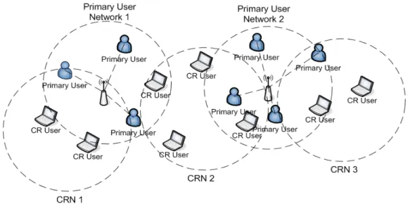
The adopted system architecture in this paper is shown in Fig. 1. Here we consider an IEEE 802.11-based service network, which consists of an access point (AP) and multiple primary users (PUs), as the primary network. Note that our approach can be extended to implement in an ad hoc network as well. The AP is responsible for channel assignments of PUs’ transmissions. On the other hand, CR users operate in an ad hoc mode, and thus these CR users form a distributed cognitive radio network (CRN).
Figure 2-1 : The adopted system architecture consisting of primary users and CR
In this CRN, we do not consider routing issue and thus all are single-hop transmissions, i.e., a pair of CR users can communicate only when they are one-hop neighbors. Besides, we make some assumptions:
1. Similar to [11, 12], each CR user equips only one transceiver, and it has the capability of sensing the presence of PUs on the channel switching to.
8
data channels.
3. When a CR user is idle, it always listens to the control channel.
4. A pair of CR users can start to transmit data packets when they find a channel which is not currently occupied by PUs and other CR users.
9
Chapter 3
The Proposed Synchronized Channel Sensing
and Accessing Mechanism
In this chapter, we introduce our proposed synchronized channel sensing and accessing mechanism. Through the proposed mechanism, a pair of CR users can find and sense an unoccupied channel efficiently, and then transmit data frames on that channel. The characteristics of our proposed mechanism include:
1. It is a distributed algorithm, and thus each pair of CR users determines an unoccupied channel independently.
2. It is a reactive spectrum sensing scheme, and thus CR users sense data channels only when they have data to transmit.
3. Primary users can easily recognize that the overheard signals are sent by a primary user or a CR user.
4. An interruption function is incorporated in our approach for primary users asking CR users to vacate the borrowed channels.
3.1 Newly defined control frames and parameters
In our approach, we define three control frames and four parameters. In the following, we use 802.11 MAC frames as an example to elaborate our protocol. However, the proposed mechanism can be applied to other contention-based wireless primary networks.
3.1.1 New Control Messages
10
receiver its transmission intention. Besides, two parameters are included in the frame: initial selected data channel ID, and increment-per-hop, both are introduced soon. RTSCR is sent at the control channel only.
(2). CTSCR: this control frame is utilized for a CR receiver to reply its CR sender
that it is idle and ready to sense the specified initial data channel. Similarly it is sent at the control channel only.
(3). Ready-To-be-Interrupted (RTI): this control frame is sent by a CR sender after receiving a data ACK from the CR receiver and is for one-hop neighboring primary users to claim the data channel, if they have data to send.
3.1.2 New Parameters
(1). Initial selected data channel ID (denoted as Ch(1)): it is randomly selected by a CR sender, and is the first data channel that the pair of CR users will switch to do channel sensing. Ch(1) is a positive integer, and 1≤Ch
( )
1 ≤N .(2). Increment-per-hop (h): it is randomly generated by a CR sender to derive the ID of next-try data channel. h must satisfy: (i) h is less or equal to the number of data channels (i.e., N), and (ii) h and N are relative primes. For example, when N=8, h could be 1, 3, 5, and 7. The reason of N and h being relative primes is to avoid many CR pairs sensing the same subset of data channels. (3). TXOPCR: the bounded time interval during which a CR user can send as many
frames as possible. The impact of a large TXOPCR value is long sensing time of
finding an available idle channel for a CR user. In this paper, the unit of
TXOPCR is frames. For example, TXOPCR is m frames indicates a CR sender
can transmit at most m frames on a data channel.
11
time interval is providing opportunities for PUs to claim channels. When a PU wants to send data at a channel, and hears a RTI control frame, it replies with a RTS and then the CR sender vacates the channel immediately. If there are multiple RTSs sent within SIFSCR and collisions occur, the CR sender detects
the presence of PUs and still returns the occupied data channel. SIFSCR is long
enough for a PU to send a RTS (i.e., SIFSCR >tRTS). In this paper, we set
SIFSCR=10×SIFS. However, it is adjustable to improve throughput
performance.
3.2 The proposed channel sensing and accessing algorithm
The proposed channel sensing and accessing algorithm for CR users consists of two phases: fast channel sensing and proactive channel vacating.
3.2.1 Fast channel sensing
When a CR sender, say CRA, intends to transmit data to a CR receiver CRB, it
first checks the availability of CRB by sending a RTSCR on the control channel. Both
the randomly generated Ch(1) and h are encapsulated in the RTSCR. The control
channel access and collision resolution are based on the CSMA/CA mechanism. If
CRB is listening to the control channel and successfully receives the RTSCR, it replies
CRA a CTSCR. At this moment, CRA and CRB achieve synchronization and switch to
channel Ch(1) for channel sensing purpose.
When hopping to Ch(1), both CRA and CRR listen to Ch(1) for t time interval to
avoid interfering on-going transmissions of PUs or CR users. Here we set t be 2ms. If
Ch(1) is still idle after t time, CRA and CRB exchange RTS and CTS as usual.
Otherwise, CRA and CRB hop to the next data channel and then sense again. The
12
collisions when more than two pairs of CR users sensing the same data channel. The next sensed data channel is determined by (1).
( )
i+1 =(
Ch( )
i +h)
modN,i≥1Ch , (1)
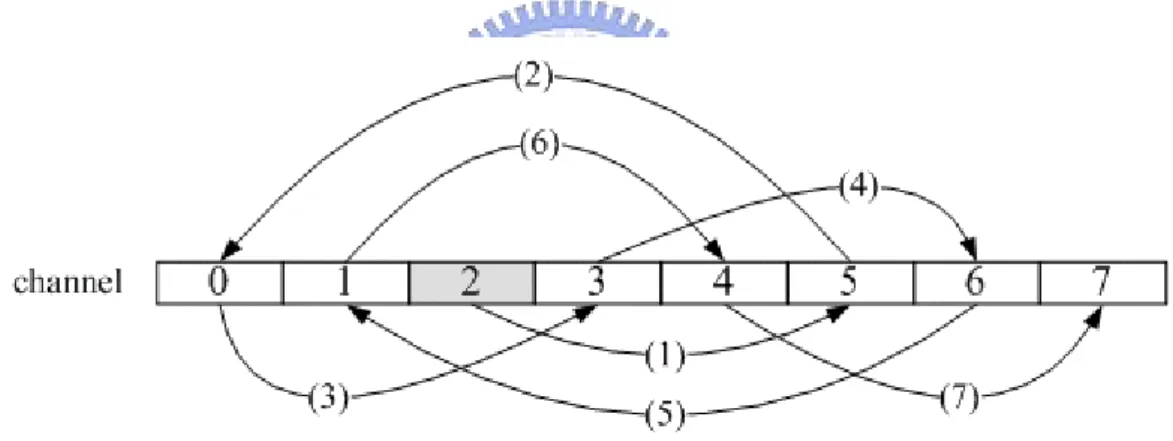
where i indicates the ith channel hopping, and N is the number of data channels. Using Fig. 2 as an example, the number of data channel N is 8 (numbered 0-7); Ch(1) and h are 2 and 3, respectively. Therefore, the pair of CR users will first sense channel 2. If channel 2 is busy, they will further sense channel 6 (because [(2+3) mod 8]=5). The complete hopping sequence is [2, 5, 0, 3, 6, 1, 4, 7, 2, 5, 0, 3, 6, …]. We observed that the hopping sequence is repeated and each channel is sensed once per run. In Chapter 5, we will evaluate the impact of different hopping generation functions on system performance.
Figure 3-1 : An illustrative example of data channel hopping sequence: N=8,
Ch(1)=2, h=3.
For a specific hopped data channel, say Ch(i), there are four possible sensing results:
(1). Ch(i) is idle for both CRA and CRB
In this case, CRA sends a RTS frame to CRB immediately and then waits for
CRA’s reply. Upon successfully receiving the CTS, CRA starts to transmit data frames
13
neighboring PUs and waits for SIFSCR so that PUs can claim the channel. Upon
receiving RTS sent by a PU, CRA and CRB vacate the data channel and hop back to the
control channel. Besides, CRA can send at most TXOPCR frames at that data channel.
If there are still queued frames to send, CRA and CRB must switch to the control
channel, and run the procedure of fast channel sensing again. The timetable of message exchanges is in Fig. 3-2(a).
(2). Ch(i) is idle for CRA but busy for CRB
Similar to case 1, CRA sends a RTS frame to CRB immediately. However, CRB
cannot successfully receive the RTS and thus it does not reply a CTS frame. After staying at Ch(i) for T time interval, both CRA and CRB hop to Ch(i+1) simultaneously.
T is the maximum time interval that CRA and CRB stay at Ch(i), and it can be derived
by CRA and CRB independently. It is obvious that T ≥t+tRTS+2SIFS+tCTS, where TS
R
t , and tCTS are the transmission time for RTS and CTS frames. In this paper, we set T =t+tRTS +2SIFSCR +tCTS. The timetable of message exchanges is in Fig. 3-2(b).
(3). Ch(i) is busy for CRA but idle for CRB
Since Ch(i) is busy for CRA, CRB does not transmit a RTS frame. After waiting
an amount of T time duration, both CRA and CRB hop to Ch(i+1). The timetable is Fig.
3-2(c).
(4). Ch(i) is busy for both CRA and CRB
Similar to case 3, CRA and CRB hop to Ch(i+1) after T time interval, and thus
the timetable is as in Fig. 3(c).
The process of data channel hopping and sensing does not terminate till CRA
14
(a) Timetable of case 1: Ch(1) is idle for both CRA and CRB
15
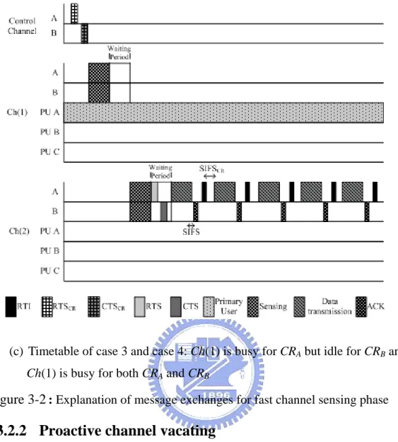
(c) Timetable of case 3 and case 4: Ch(1) is busy for CRA but idle for CRB and
Ch(1) is busy for both CRA and CRB
Figure 3-2 : Explanation of message exchanges for fast channel sensing phase
3.2.2 Proactive channel vacating
There are two situations for a CR pair to vacate the occupied data channel: one is they have accessed the data channel long enough (i.e., it has already transmitted
TXOPCR frames at that data channel), and the other is PUs want to claim that data
channel. For the former, the CR sender and receiver stop transmitting/receiving data frames and then hop back to the control channel, as described in Chapter 3.2.1. Our phase 2 design focuses on the latter. To be aware of the presence of potential primary senders, there must be a mechanism for potential primary senders to interrupt the transmissions of a CR pair. The design challenges of this interruption mechanism are twofold: how does a potential primary sender recognize that the data channel is
16
occupied by a CR pair or other primary users, and how to make a CR pair to automatically return the borrowed data channel. We elaborate our interruption mechanism in the following. Both challenges are dealt with RTI control frame.
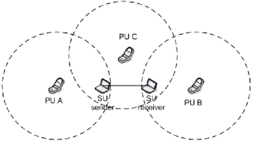
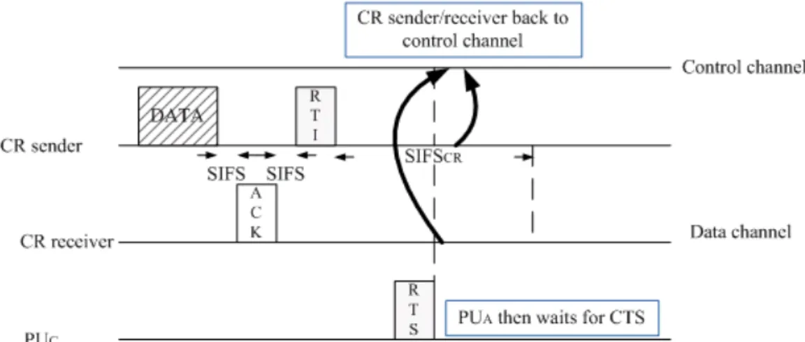
Figure 3-3 : An illustrative example for explanation of fast channel sensing phase
After transmitting a data frame and successfully receiving the ACK, a CR transmitter sends a RTI frame and then waits for SIFSCR long. Within this time
duration, potential primary senders are able to send RTS to its intended primary receiver. Upon receiving RTS messages, the CR sender/CR receiver knows the presence of primary users, and they will hop to the control channel. There are three possible actions after a CR sender transmitting a RTI:
(1) Case 1: the potential primary sender is a neighbor of the CR sender, while it is not a neighbor of the CR receiver
In Fig. 3-3, PUA is such a potential primary sender. PUA sends a RTS frame upon
receiving RTI frame. The CR sender then stops transmitting data and hops back to the control channel. In the meantime, the CR receiver does not receive further data frames, and thus is aware that the CR sender must be interrupted by a potential primary sender. The CR receiver hops back to the control channel, too. If the CR sender still has data for the CR receiver, it generates a new initial data channel ID and increment-per-hop,
17
and sends communication invitation on the control channel. The corresponding timetable of message exchanges is in Fig. 3-4(a).
(2) Case 2: the potential primary sender is a neighbor of the CR receiver, but it is not a neighbor of the CR sender
Again in Fig. 3-3, PUB is such a potential primary sender. When the CR sender
sends a RTI frame, the CR receiver is idle for SIFSCR long. Since tSIFSCR is longer
than tDIFS, thus PUB can send a RTS frame to its receiver. At this time, the CR
receiver is aware of the presence of a primary sender. The CR receiver hops back to the control channel. Though the CR sender keeps sending data frames, it does not receive any ACKs from the CR receiver. Therefore, the CR sender vacates the occupied data channel and hops back to the control channel, too. The corresponding timetable of message exchanges is in Fig. 3-4(b).
(3) Case 3: the potential primary sender is a neighbor of the CR sender and the CR receiver
PUC is such a potential primary sender shown in Fig. 4. Both the CR sender and
the CR receiver receive the RTS frame sent by PUC, and then hop back to the control
channel. The corresponding timetable of message exchanges is in Fig. 3-4(c).
The detailed flow chart of our proposed channel sensing and accessing mechanism is summarized in Fig. 3-5.
Here is a little discussion. In this paper, it considers that there is no retransmission mechanism for CR users, and if there is no ACK replied by CR receiver because of the packet loss, the CR pair will also think that the channel is claimed back by PU, although it is not true. Because of these situations, if there has retransmission
18
mechanism for CR users, the CR receiver may reply a NACK in case of the receiver does not receive the data frame correctly. If the CR sender receiver the NACK, that means it is just a packet loss occur, it is not a PU cliam back the data channel, then it will do the retransmission of frame.
(a) Timetable of case 1: PUA is a neighbor of CR sender
19
(c) Timetable of case 3: PUC is a neighbor of CR sender and CR receiver
Figure 3-4 : Explanation of message exchanges for proactive channel vacating
phase
20
Chapter 4
Performance Analysis
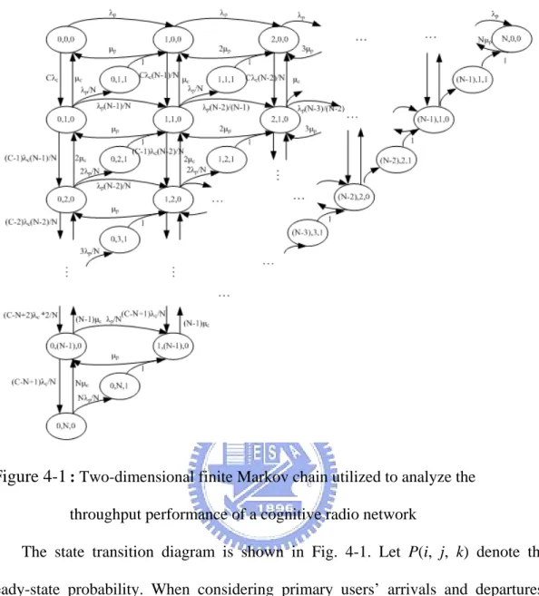
In this chapter, we model the process of channel occupation of our approach as a continuous-time Markov Chain, and then analyze our approach. We assume there are N data channels and C pairs of cognitive radio users. The probability of channel selection of primary users is uniform distribution. Though randomly selecting an initial data channel ID and an increment-per-hop, we assume each data channel has the same probability to be sensed. Therefore, we assume that the probability of data channel selection for cognitive radio users is uniform distribution, too. The traffic arrival rates of primary and cognitive radio users are λp and λc respectively which
are both the Poisson distribution. Beside, the corresponding service time of primary and cognitive radio users is exponential distribution with rates μp and μc. In this Markov Chain, states are described by an integer set (i, j, k), where i is the number of channels occupied by primary users, j is the number of channels that are occupied by cognitive radio users, and k is an event indicator. If k equals to 1, it indicates that a primary user is trying to sense and access a data channel, which is occupied by a CR user. In such case, the primary user waits for a RTI frame to claim the channel; otherwise, k equals to 0, which means no interruption occurs. Besides, the number of free channels is (N-i-j). For example, state (2, 1, 1) denotes that there are three busy data channels: two is occupied by primary users and one is occupied by a pair of CR users. In addition, a primary user is trying to access the data channel been currently occupied by that CR pair.
21
Figure 4-1 : Two-dimensional finite Markov chain utilized to analyze the
throughput performance of a cognitive radio network
The state transition diagram is shown in Fig. 4-1. Let P(i, j, k) denote the steady-state probability. When considering primary users’ arrivals and departures, state (i, j, 0) may transit to states (i-1, j, 0), (i+1, j, 0), or (i, j, 1) followed by (i+1, j-1, 0). The probabilities of state transitions from (i, j, 0) to (i-1, j, 0) and (i+1, j, 0) are
p iμ and i N j i N p − − −
λ , accordingly. The state transition from (i, j, 0) to (i, j, 1) indicates that a primary user is trying to access the data channel occupied by a pair of CR users, and thus triggers an interruption with probability
N j
p
λ . In such case, the interrupted cognitive radio user must return the occupied data channel to the primary user. Therefore, probability of state transition from (i, j, 1) to (i+1, j-1, 0) is 1.
22
Considering CR users’ arrivals and departures, state (i, j, 0) may transit to state (i, j+1, 0) and state (i, j-1, 0) with probability
(
)
N j i N j C− λc − − and jμc, respectively. Note that
(
)
N j i N− −is the probability that a new pair of CR users sense an idle channel.
For a specific steady state, according to the principle of flow conservation that input flow rates equal the output flow rates, we derive the corresponding balance equations, as follows.
For those states whose , and ,
, (2) where
( )
⎩ ⎨ ⎧ = = elsewhere j j , 0 0 , 1 σ .Besides, for those states whose , and , k=0, we derive
, (3) where
( )
⎩ ⎨ ⎧ = = elsewhere i i , 0 0 , 1 σ .Further, the derived equation of state (0, N, 0) is
23
(4) For those states whose ,
. (5) Finally, for , we know
(6) For the transient states that
Then, the interrupted probability (denoted as ) of CR users equals to the sum of total interrupted states, i.e.,
From Eqs. (2)-(8), we know
Thus the total throughput of primary users (denoted as ) is
By applying matrix operations, we can solve all state probabilities. The throughput performance of CR users (which is the metric we are interested in and is denoted as
) is given as
24
Chapter 5
Simulation and Analytic Results
To evaluate the performance of the designed channel sensing and accessing algorithm presented in chapter 3 and to validate the analytic model presented in chapter 4, we develop a simulation program to discover the system throughput of a cognitive radio network, and the impact on primary users. We compared our approach with [5], i.e., OSA-MAC, and with [7], i.e., Channel-hopping based MAC. Again, we only consider single-hop flows of cognitive radio users.
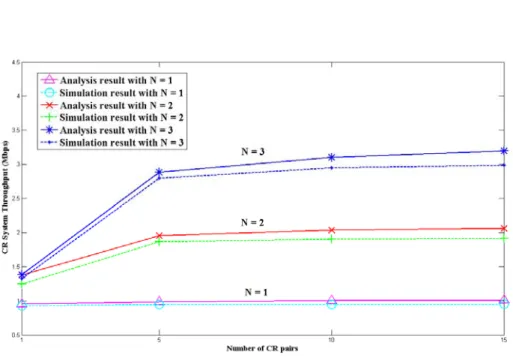
We first compare the CRN throughput of analytic and simulation results upon the same parameter settings (listed in Table 1). We vary the number of data channels from 1 to 3. Besides, we assume CR users are always backlogged, and thus the arrival rates of primary users and cognitive radio users are 0.4 and 1, respectively. The service rate of primary users is 0.667. The CRN throughput is shown in Fig. 5-1. Though the analytic and simulation results are almost consistent, there exists discrepancy. The maximum error, which occurs at N=1 and C=15, is less than 6% ((3.17-3)/3.17 = 5.3%). There are two reasons, one is our analytic model does not take sensing time into consideration, while it is an overhead in our simulation. Another one is about the channel selection. In our analytic mode, it considers that the probability of choosing each channel is even, that means if there is N data channel, the probability of choosing each channel is all equal to 1/N. But in simulation, because of the randomly choosing Ch(1) and h, the probability of choosing each channel may not be even. It effects on the spending time on sensing idle channel.
25
Table 1. Parameter settings of simulation Parameter Value Frame size 2048bytes Number of data Channels (N) 5
SIFS 0.01ms SIFSCR 0.1ms
DIFS 0.05ms Simulation time 100s Sensing time for a data channel 2ms
Figure 5-1 : The analysis and simulation throughput performance of a CRN
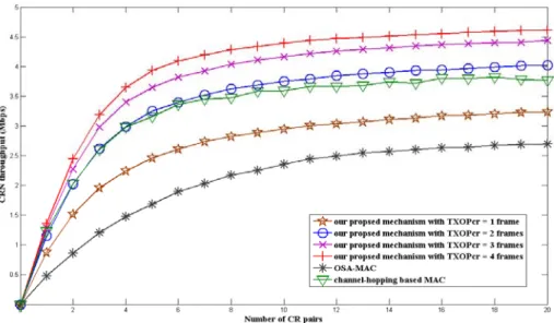
Next, we compare the performance of our mechanism, OSA-MAC and
Channel-hopping based MAC. In this experiment, there are six channels: one is control channel, and the others are data channel. Each data channel is occupied by primary users with Poisson arrival distribution. Cognitive radio users are always backlogged. Settings of simulation parameters are the same as in Table 1. The
throughput of a considered CRN is shown in Fig. 5-2. We observed that our proposed mechanism outperforms OSA-MAC. The reason is, in our approach, a CR sender can
26
transmit multiple frames (the maximum is TXOPCR frames) when an available data
channel is sensed. Contrarily, in OSA-MAC, a CR sender only transmits one frame at a time. Note that our approach still performs better than OSA-MAC upon TXOPCR=1.
The reason is that the sensing time our approach is shorter than that of OSA-MAC. On the other hand, our approach performs is worse than Channel-hopping based MAC when TXOPCR = 1. It is because it doesn’t have to exchange control message to
negotiating about the potential sensing channel. But when TXOPCR >=2, our approach
will be better than his. This result thanks to the interrupt mechanism, less collision and longer accessing time makes our approach’s throughput get better. We further investigate the impact of TXOPCR on primary users. We found that it has no impact
on the throughput performance of primary users, shown in Fig. 5-3. Thanks to the designed interruption mechanism so that primary users can claim borrowed data channels in time.
27
Figure 5-2 : The simulation throughput performance of a CRN
Figure 5-3 : PU throughput vs. the number of CR pairs, upon PUs utilizing 40% bandwidth
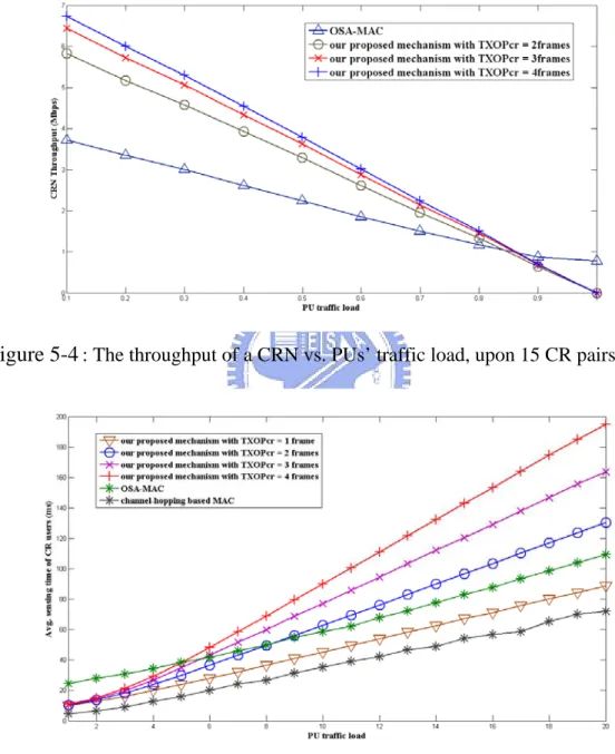
Followed, we investigate the impact of primary users’ traffic load on CR users’ throughput, and the result is shown in Fig. 5-4. Here we set the number of CR pairs be 15, and vary primary users’ traffic load from 0.1 to 1. For example, 0.2 traffic load indicates that primary users generate packets to utilize 20% bandwidth in total. Our proposed mechanism achieves a higher throughput than OSA-MAC, except when primary users’ traffic load is larger than 0.85. Specifically, the CRN throughput of our
28
algorithm is zero when PUs utilize all bandwidth; contrarily, OSA-MAC still has 0.77 Mbps throughput. The reason is in OSA-MAC, CR users are able to send data frames on not only data channels, but also the control channel. Thus CR users can send frames on the control channel, even if they cannot borrow data channels from PUs.
Figure 5-4 : The throughput of a CRN vs. PUs’ traffic load, upon 15 CR pairs
Figure 5-5 :Average sensing time of CR users vs. the number of CR pairs upon PUs utilizing 40% bandwidth
Though a CRN has a good throughput performance upon a large TXOPCR value,
29
average sensing time of OSA-MAC and our approach increases as the number of CR pair increases. Specifically, a large TXOPCR value indicates that a CR user can
transmit more data packets before vacating the occupied data channel and thus other CR users will spend much more time on data channel sensing. In addition, the average sensing time of OSA-MAC is longer than that of our approach when the number of CR pairs is few. The reason is OSA-MAC consists of three phases, and all CR users are synchronized when executing each phases. In other words, though a CR user has already sensed an unoccupied data channel and finish its one-frame transmission, it cannot start channel selection phase immediately. Instead, it waits for the beacon of next beacon interval. However, when the number of CR pair increases, OSA-MAC has a lower average sensing time compared to our approach. This is because, for OSA-MAC, a CR sender only transmits one data frame when occupying a data channel.
From Figs. 5-2 and 5-5, we observe that there is a trade-off between CRN throughput and data channel sensing time. If most of the CR traffic load is non-real time data type, the major performance evaluation metric is “throughput”. Thus a large
TXOPCR value results in a high throughput performance and is a suitable parameter
setting. However, if some CR traffics are real time data type, a small TXOPCR value is
better to achieve QoS requirement.
We then observe the impact of frame size on the performance of primary users, and the simulation results are shown in Figs. 5-6 and 5-7. Here we set the number of CR flows be 15. It is straightforward that when frame size increases, the CRN throughput increases significantly. Contrarily, the throughput of PUs decreases slightly, and the decrement is less than 1.25%, as shown in Fig. 5-6. Again, thanks to the designed interruption mechanism which shortens the average waiting time of
30
primary users to claim data channels, as shown in Fig. 5-7.
Figure 5-6 : Throughputs of PUs and CR users vs. CR frame size, upon 15 CR pair
Figure 5-7 : The average waiting time of PUs vs. CR frame size, upon 15 CR pairs
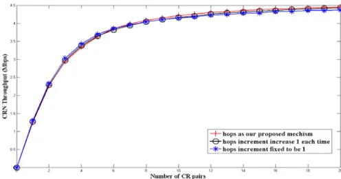
Figure 5-8 : Throughput of a CRN vs. number of CR pairs of various generation functions
31
Followed, we compare the throughput performance of various generation functions of hopping sequence. Specifically, the initial channel Ch(1) is intact for all generation functions, and each generation function has its own increment-per-hop pattern. In this experiment, we examine three increment-per-hop patterns. The first approach is fixed increment-per-hop (denoted as “fixed-h” and it is adopted in our proposed channel sensing mechanism), and the next hopped data channel is
Ch(i+1)=[(Ch(i)+h) mod N]. The second approach is linear increment-per-hop
(denoted as “linear-h”), and the next hopped channel is Ch(i+1)=[(Ch(i)+h+(i-1)) mod
N)]. The last approach does not utilize increment-per-hop and the next hopped
channel is Ch(i+1)=[(Ch(i)+1)) mod N]. We denote the third approach “without-h”. For example, the number of data channels N is 5 (numbered from 0 to 4), the initial channel ID is 3, and initial increment-per-hop is 2. The channel hopping sequences of fixed-h, linear-h, and without-h are [3, 0, 2, 4, 1, 3, 0, 2, 4, 1, …], [3, 1, 0, 0, 1, 3, 1, 0, 0, 1, …], and [3, 4, 0, 1, 2, 3, 4, 0, …]. The throughput performance is in Fig. 5-8. We found data channel hopping sequence do not impact on CRN throughput. It is expectable that fixed-h and without-h perform similarly, and the reason is that for both generating functions, a CR user senses every data channel once per run, while with different order. It is interesting that for linear-h, a CR user only senses three out of five data channels, while still performs similarly to others. Thus we conclude no matter “sensing all channels per run” or “sensing subset of channels per run,” our designed mechanism performs similarly.
Then we present the performance of channel utilization, including PUs and CR users. This experiment is to show the improvement degree of channel utilization. We set the number of data channels be five, and primary users utilize 40% bandwidth. Fig. 5-9 is the throughput performance of TXOPCR =2, andFig. 5-10 is that of TXOPCR =4.
32
When the number of CR pairs is larger than 10, the overall channel utilization achieves over 75% (7.5Mbps/10Mbps=0.75) and the corresponding improvement degree of channel utilization contributed by CR users is 46% (3.5Mbps/7.5Mbps), as shown in Fig. 5-11. When TXOPCR =4, the channel utilization further increases to
85%, and the throughput of CR users even higher than that of PUs.
Figure 5-9 : Channel utilization vs. number of CR pairs, upon TXOPCR = 2 frames,
N=5, PUs utilizing 40% bandwidth
Figure 5-10 : Channel utilization vs. number of CR pairs, upon TXOPCR = 4frames,
33
Then, we examine how RTI messages impact on primary users. Without transmitting RTI messages periodically by CR users, primary users cannot interrupt CR users’ transmissions as quick as possible. Instead, a primary user cannot start to transmit data packets till the ongoing transmission is completed. In such case,
TXOPCR value does impact on PUs’ throughput performance. A large TXOPCR value
indicates that PUs must wait for a long time to claim data channels, and thus PUs’ throughput decreases, as shown in Fig. 5-11. On the other hand, the throughput of CR users increases as TXOPCR value increases, as what we expected. On the other hand,
without RTI, CR users in our proposed mechanism utilize more bandwidth and have higher throughput performance, as shown in Fig 5-12.
Figure 5-11 : Throughput of PUs vs. number of CR pairs without RTI, upon N=5, PUs utilizing 40% bandwidth
34
Figure 5-12 : Throughput of CR users vs. number of CR pairs without RTI, upon
N=5, PUs utilizing 40% bandwidth
Finally, we consider that if the packet error in the network is getting high, whether it causes a high traffic load on the control channel. So, we will show how does the packet error rate matters to the number control frames on the control channel. In Fig. 5-13, we could see that the number of control frames on control channel will increase as the packet error rate increases. It is because when a packet error is occurred, the CR receiver will not reply an ACK, and the CR pairs would think the channel is claimed back of PU, so the CR pair will switch back to the control channel and exchange the RTSCR/CTSCR again. It makes more control frames exchanged on the control channel
35
Figure 5-13 : Number of control frames sent on control channel vs. packet error rate, upon N=5, PUs utilizing 40% bandwidth
36
Chapter 6
Conclusion and Future Work
In this paper, a synchronized channel sensing and accessing mechanism for cognitive radio users has proposed. This mechanism consists of two phases: fast channel sensing and proactive channel vacating. One unique design in our protocol is interruption mechanism, which is achieved by employing RTI control frames. Through the assistance of RTI, we balance the tradeoff between throughput performance of a CRN and PUs’ channel claiming time. Indeed, primary users may not be able to identify RTI frame due to CR users operating in a dissimilar network system. This problem can be easily solved through adjusting the value of SIFSCR to
make primary users “believe” channels are idle and are able to send transmission invitations to intended receivers. Then the function of RTI frame is to let the neighbor of CR user know the channel is not be released, the channel is just waiting for primary user to claim it back. Also for the receiver side, the ACK is having the same function to RTI here. An analytical model was developed to evaluate the theoretical performance of our protocol. Computer simulation was conducted to demonstrate the superior performance of our protocol over that of OSA-MAC.
REFERENCES
[1] FCC Spectrum Policy Task Force, “Report of the spectrum efficiency working group,” Federal Communications Commission, Technical Report 02-155, 2002.
37
[2] T. Yucek and H. Arslan, “A survey of spectrum sensing algorithms for cognitive radio applications,” IEEE Communications Survey and Tutorials, pp. 116-130, vol. 11, no. 1, 2009
[3] C.-C. Hsu, S. L. Wei and C.-C. Kuo, “A Cognitive MAC Protocol Using Statistical Channel Allocation for Wireless Ad-hoc Networks,” in Proc. of IEEE
Wireless Communications & Networking Conference, pp. 105-110, 2007.
[4] Y.R. Kondareddy, and P. Agrawal, “Synchronized MAC Protocol For Multi-hop Cognitive Radio Networks,” in Proc. of IEEE International
Conference on Communications, pp. 3198– 3202, 2008.
[5] L. Long, and E. Hossain, “A MAC Protocol for Opportunistic Spectrum Access in Cognitive Radio Networks,” in Proc. IEEE of Wireless Communications &
Networking Conference, pp. 1426– 1430, Las Vegas, March 2008.
[6] Juncheng Jia and Qian Zhang, “Hardware-constrained Multi-Channel Cognitive MAC” in Proc. IEEE Global Communication Conference, pp. 4653– 4658, 2007.
[7] Hang Su and Xi Zhang, “Channel-Hopping Based Single Transceiver MAC for Cognitive Radio Networks”, in Proc. IEEE Communication and Information
Systems Security, pp. 197– 202, 2008.
[8] J. Mo, H. -S. W. So, and J. Walrand, “Comparison of multi-channel MAC protocols,” IEEE Trans. Mobile Comp., vol. 7, no. 1, pp. 50-65, Jan. 2008. [9] P. Bahl, A. Chandra, and J. Dunagan, “SSCH: Slotted seeded channel hopping
for capacity improvement in IEEE 802.11 ad hoc wireless networks,” in Proc.
of Annual International Conference on Mobile Computing and Networking, pp.
315-329, 2004.
38
multi-channel hidden terminals using a single transceiver” in Proc. of ACM
International Symposium on Mobile Ad Hoc Networking and Computing, 2004,
pp. 222-233.
[11] D. Cabric, A. Tkachenko, and R. W. Brodersen, “Experimental study of spectrum sensing based on energy detection and network cooperation,” in Proc.
of ACM Int. Workshop on Technology and Policy for Accessing Spectrum
(TAPAS), Article No. 12, Aug. 2006.
[12] S. Haykin, “Cognitive Radio: Brain–Empowered Wireless Communications,” in
IEEE Journal on Selected Areas in Communications, vol. 23, no. 2, pp.