Motion Planning for a Humanoid Walking in a 3D Space
Tsai-Yen Li
Computer Science Department
National Chengchi University,
Taipei, Taiwan, R.O.C.
[email protected]
Pei-Zhi Huang
Computer Science Department
National Chengchi University,
Taipei, Taiwan, R.O.C.
[email protected]
Abstract
Most motion planners solve problems defined in a 2D workspace for mobile robots or in a 3D workspace for fixed-based manipulators or free-flying objects. Human beings move on a smooth or stair-like 2D surface of a 3D workspace. Such a motion-planning problem differ from the general piano mover’s prob-lem on that the definition of obstacle region not only depends on the local relative height but also on the capability of a humanoid such as foot length. In this paper, we describe a planner capable of generating humanoid motions in 3D space on stair-like terrains by taking the human foot length and personal pref-erence into consideration. A gross motion plan that satisfies the constraints is produced and passed to a locomotion generator that generates an appropriate human walking motion. Our experiments show that the planner is efficient and can be used to generate real-time humanoid animations on stair-like terrains.
Keywords: Gross Motion Planning, Path Planning,
Humanoid, and Robotics.
1. Introduction
Great advances in mechanical design and control have been made in recent years in designing a hu-manoid robot. Consequently, the software framework that controls the behaviors of a humanoid robot be-comes crucial in such a system. Many algorithms addressing the high-level intelligence that we usually expect from a humanoid robot have been proposed in the past few years. Unlike earlier researches focusing on generating stable motions for robots on uneven terrain; recent works has been focused on synthesiz-ing visually realistic motions for real-time animation and control of humanoids. Most of these researches were driven by the applications in the entertainment industry or by the visible humanoid projects world-wide. Despite many great research results on
human-oids have been proposed, most of them do not ad-dress the problem of gross motion planning that gen-erates feasible motions for a humanoid to reach a goal. The path that a humanoid follows is usually given as an input. Exceptions include [9] and [18]. However, in these researches, a flat ground with ob-stacles is usually assumed such that the problem can be defined and solved with the general mo-tion-planning algorithms.
The basic motion-planning problem, called the
find-path problem or the piano mover’s problem, is
about finding a collision-free path for a robot moving in a workspace cluttered with obstacles.[12] The problem is originally motivated with the objective of automatically generating motions for mobile robots or manipulator arms. Depending on applications, a motion planner typically defines the problem in a 2D or 3D workspace. For example, if the robot is a mo-bile robot, due to its capability limitation, one usually can reasonably simplify the problem into a holonomic or nonholonomic problem in a 2D work-space. On the other hand, if the robot is a manipula-tor or a free-fly object, the problem must be defined in 3D workspace. The gross motion planning for a humanoid robot is between these two extremes since a regular humanoid robot can climb up or step down stairs but it also needs to stay on the ground all the time. This type of workspace is sometimes called two-and-half dimensional workspace.
In this paper, we propose a motion-planning system capable of generating walking motions for a human-oid to reach a goal on a stair-like terrain. We assume that the system is given an elevation description of the obstacles in the workspace and accept a goal-oriented command from a user. The system will generate a feasible global path and the associated locomotion that brings the humanoid to reach the goal. At the first glace, the problem is similar to the general path-planning problem. However, since the definition of obstacles for this problem depends on Appear in Proceeding of 2001 National Computer Symposiim (NCS2001), Taiwan, 2001
the relative height locally and the foot length of the humanoid, the problem definition deserves further clarification. In addition, when we extend the prob-lem to the third dimension, a user may have personal preferences on paths if the goal can be reached via various paths of different heights.
The rest of the paper is organized as follows. We will first review related work in motion planning and humanoid in the next section. We will then give a more detailed description of the problem we consider in this paper as well as the approach we have taken. In Section 4, we will show our experimental results for three example scenarios. Finally, we will con-clude our work in the last section.
2. Related Work
The gross motion-planning problem was originally brought up in the context of robotics to generate col-lision-free path for robots. A survey of approaches to the problem can be found in [6] and [12]. According to [2], most planners solve this problem with two phases. The first phase, called preprocessing phase, converts the geometric problem into a problem with abstract data structure (ADT) such as a graph. This ADT will then be searched for a feasible path in the query phase. Generally speaking, early research fo-cuses on developing theoretical foundation and com-plete solutions for the problem.[4][16] Due to the curse of dimensionality, several researches in the last decade proposed practical solutions that can be ap-plied to wider arrange of applications despite they usually lack completeness[3][7].
Many efficient planners have been proposed to solve the problem for objects with low degrees of freedom (DOF’s) (typically less than or equal to four). Most of these planners are complete planners because they can always give a correct answer (success or failure) to the given problem. Among these planners, the po-tential-field based approach is the most popular one. They compute an artificial potential field in the workspace as the heuristic to search the configuration space for a feasible path.[3] For this type of planners, the main challenge falls on making the planner suit-able for on-line or real-time applications.[13][14] For problems with more than four DOF’s, randomized approaches usually are unavoidable for answering a planning query very quickly. Typically such planners include RPP [3] and PRM [7] planners. The PRM planners spend a significant of time in the preproc-essing phase to construct a representative roadmap in the freespace. Variations of sampling strategies have been proposed for a generic or a specific
prob-lem[1][11][17].
The researches of generating humanoid motions can be found in the literatures of robotics and computer animation. Although various aspects of motion gen-eration have been studied, we will only concern the lower-body motion and the resulting body displace-ment. Early research focuses on generating a dy-namically stable motion for a given path on a flat or uneven ground.[8][15] Although the locomotion for regular walks can be computed kinematically, many approaches choose to use or modify motion-captured data due to the complexity of a human figure. Tech-niques such as motion warping[19] or dynamic fil-tering[20] are often used to ensure that the captured motions can be transformed into a dynamically cor-rect one. However, not until recent years, the prob-lem of gross motion planning becomes one of main concerns of the humanoid research in robotics and computer animation.[9][10][18]
3. Motion Planning for Humanoids
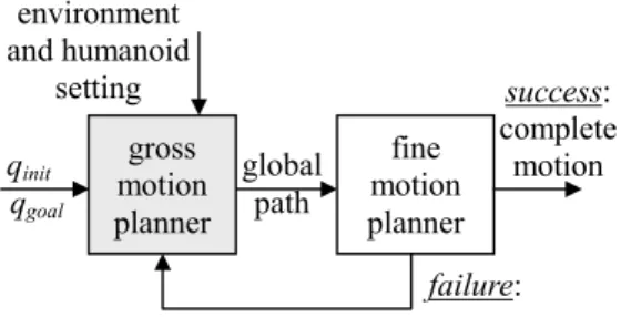
Depending on motion granularity, the mo-tion-planning problem can be classified into gross motion planning and fine motion planning. For the problem of walking on an uneven terrain for a hu-manoid, both types of planning needs to be consid-ered in order to guarantee the success of accom-plishing the desired task. Like most motion planning problems for industrial robots, we think the gross motion planner and fine motion planner can be de-fined separately. However, they should be integrated in a loop where they can be solved sequentially and connected with feedbacks as shown in Figure 1. The gross motion planner on the left will be the focus of this paper. The planner is supposed to generate a global path for the humanoid to follow. However, the fine motion planner may fail to generate detailed locomotion for the given path. In this case, the plan-ner should feedback the failure, possibly with rea-sons, to the gross motion planner to compute another global path. Nevertheless, taking this decoupled viewFigure 1. Planning loop for a typical query gross motion planner fine motion planner global path success: complete motion environment and humanoid setting qinit qgoal failure:
has greatly reduced the complexity of such a plan-ning problem.
3.1. Problem description
We assume that we are given a geometric description of the workspace as well as the foot length of a hu-manoid. The workspace contains an uneven terrain or objects with various heights. The set of all possible configurations q for the humanoid define the so-called Configuration Space (C-space for short), denoted by C. Unlike the basic path-planning prob-lem where the definition of obstacles is rather straightforward, the obstacles in the motion-planning problem for humanoid walking are not explicitly given. Instead, an object is an obstacle to a humanoid only if there is no way for the humanoid to step onto the object due to its height. In addition, a humanoid must stand on a large enough area in order to main-tain a stable stance. If the ground of the workspace is described as a smooth curve, the slope of the curve cannot be too large to cause foot slippery. In sum, the planning problem is rather complex in real life, and we need to make reasonably assumption to simplify the problem.
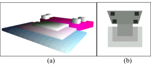
First, we assume a discrete representation of the workspace. We could be given a continuous function for the elevation of the ground or be given a polygo-nal description of the objects. However, we assume that we can convert these descriptions into an eleva-tion grid of some resolueleva-tion. Each cell in the grid contains an elevation value for the whole cell. An example of workspace with the stair-like terrain is shown in Figure 2. The elevation for each cell in the grid (128x128) is represented by a gray-scale value in Figure 2(b). Second, we assume that the resolution of the elevation grid is coarse enough for a human-oid’s feet to step onto. The maximal height that a humanoid can step onto is denoted by h, which is a property of the given humanoid. Third, we assume that a humanoid will not stay on the obstacle boarder with a height difference for more than some desig-nated units of time, m. We assume that this situation
happens when the geometry of a humanoid intersects the boarder. This assumption is to make sure that the humanoid does not stay on the unstable region except for the trespassing purpose. Fourth, we assume that the geometry of the humanoid can be simplified to an enclosing circle of radius r such that the orientation dimension can be ignored at planning time. We as-sume that a humanoid will always face forward and we can recover its orientation in a postprocessing step.
3.2. Reachability map and instability map
Suppose that we are given a height map containing the elevation value of each cell in the workspace grid. As indicated in the previous subsection, a cell is considered an obstacle cell if and only if there are no ways to reach the cell from its neighbors under the height constraint. Given an initial configuration of the humanoid, we can compute a map, calledreach-ability map, where obstacle regions are composed of
the cells that cannot be reached. This map can be computed by a wave propagation algorithm such as the one used to construct NF1 potential field.[12] The only difference is that we advance to a cell only if the height difference is less than h. We can convert this map, built in the workspace, into its correspond-ing C-space by growcorrespond-ing the obstacle regions with the radius of the humanoid. The resulting C-space map can then be used to build a potential field to guide the search in the planning process.
As mentioned in the previous subsection, we need to identify the regions where unstable situation might occur if a humanoid stay there for too long. A map describing the regions is called instability map. Three states are possible for a cell in this map: free,
unsta-ble, and forbidden. A cell is considered free if and
only if there exist no height difference in the region covered by the enclosing circle of a humanoid. If there exist height differences, a cell could be defined as unstable or forbidden depending on whether the maximal height difference is greater than foot length. One can compute such a map by first identifying the cells with different heights in their neighborhood. We can then grow these cells by the radius r to form the final instability map. These two maps will be used in the planning algorithm presented in the next subsec-tion.
3.3. Path planning algorithm
The planning algorithm that we used to compute the humanoid motion is shown Figure 3. The STA-BLE_BFP algorithm is similar to the classical Best-First Planning (BFP) algorithm that is used to solve path-planning problems with low DOF’s. In
(a) (b)
Figure 2. An example of stair-like terrain: (a) 3D model (b) elevation in gray scale
each iteration of the search loop, we use the FIRST operation to select the most promising configuration
q from the list of candidates (OPEN) for further
exploration. We visit each neighbor q’ of q and check their validity (via the LEGAL operation) for further consideration. A configuration is legal if it is colli-sion-free, marked unvisited, and temporarily stable. It is temporarily stable if and only if the humanoid have not entered the unstable region for too long. This duration is kept as an instability counter in each cell in the unstable region when we propagate nodes in it. Note that the validity of a configuration in the unstable region depends on the instability counter of the parent configuration. If there are more than one possible parent configurations, we cannot exclude any of them. Therefore, in the STABLE_BFP algo-rithm, we do not mark a configuration visited if it is in the unstable region. A configuration in this region can be visited multiple times as long as the instability counter does not exceed the maximal value.
In the STABLE_BFP algorithm, we use FIRST op-eration to select the most promising configuration for further exploration. In the case of the BFP planners, the artificial potential field is usually the only index for goodness. Planners with this approach can usu-ally yield short paths. In our case, the height differ-ence could be an important index as well since one may prefer climbing up or stepping down stairs to taking a longer path. Therefore, in the FIRST opera-tion, we use a linear combination of both criteria (potential for horizontal measures and height differ-ence from qg for vertical measures), whose weights
can be specified by the user.
3.4. Postprocessing
If our planner succeeds in finding a feasible path for a humanoid, we need to perform two things in the postprocessing step. First, we can convert the found path into a smooth one via a smoothing routine. The smoothing algorithm is very similar to the ones for typical path planners. One usually replaces a subpath in the original path continuously with a straight-line path segment in a smoothing routine. A major differ-ence for smoothing a path in the new planner is on the metric for measuring distance. This metric is de-fined with the same criteria as in the FIRST proce-dure such that the user preference can be preserved. Finally, we have to recover the orientation parameter of the humanoid in each configuration of the path. If the path contains a sharp turn that is hard for a hu-manoid to follow, we can add additional steps into
(a) (b)
(c) (d)
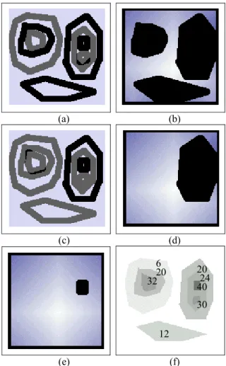
(e) (f) Figure 4. Effects of foot length (10, 15, and 20) on
the reachability map and the instability map STABLE_BFP()
1 install qi in T;
2 INSERT(qi, OPEN); mark qi visited;
3 SUCCESS ← false;
4 while ┐EMPTY(OPEN) and ┐SUCCESS do 5 q←FIRST(OPEN);
6 for every neighbor q’ of q in the grid do 7 if LEGAL(q’) then
8 if q’ is unstable then 9 q’.cnt=q.cnt+1; 10 else
11 mark q’ visited;
12 install q’ in T with a pointer toward q;
13 INSERT(q’, OPEN);
14 if q’ = qg then SUCCESS ← true;
15 if SUCCESS then
16 return the backtracked feasible path 17 else return failure;
Figure 3: The STABLE_BFP algorithm
6 20 32 20 12 24 40 30
the path to slow down the orientation change.
4. Experimental Results
The aforementioned planner has been fully imple-mented in Java. The planning times reported in this paper were collected from experiments running on a regular PC with a PIII 600 MHz processor. The size of the workspace (x, y) for all examples shown in this paper is 128x128.
4.1. Experiments with different foot lengths
In Figure 4, we show the effects of foot length on the reachability map and the instability map for an ex-ample of stair-like workspace. The height map for the workspace is depicted with gray scale in Figure 4(f). If the foot length is set to 10, the reachability map and instability map are shown in Figure 4(a) and 4(b), respectively. Note that the relative heights of four objects are larger than 10 but the unreachable region contains only three obstacles since one of them is enclosed by another. If the foot length is raised to 15, the same two types of maps are shown in Figure 4(c) and 4(d), respectively. Finally, if the foot length is increased to 20, only one obstacle is left (Figure 4(e)). In the reachability map, we also show the potential field built from an initial configu-ration with the NF1 method.4.2. Experiments with different preferences
In the STABLE_BFP algorithm, we use two indices for the “best” criteria. One of them is the potential value Uh (horizontal distance) while the other isab-solute value of relative elevation Uv (vertical
dis-tance). Both indices are referenced from the goal configuration, and the smaller the value, the better. The following linear combination of both indices are used: U = (1-α) * Uh + α * β * Uv , where α is the
weight (between 0 and 1) of horizontal distance and β is the coefficient to normalize the vertical distance to make both indices comparable. In Figure 5, we show an example with different user preferences. The height map, instability map, and reachability map for the workspace is shown in Figure 5(a)-5(c), respec-tively. In Figure 5(d), we show the path found by the planner with α being set to 5%. This means that the user prefers a longer path with less elevation changes. In Figure 5(e) and 5(f), α is set to 50% and 95%, respectively. The path lengths for these three cases are 250, 149, and 95, respectively. In the last exam-ple, the humanoid had to step up and down two ob-jects in order to reach the goal with a shortest path.
4.3. 3D animation examples
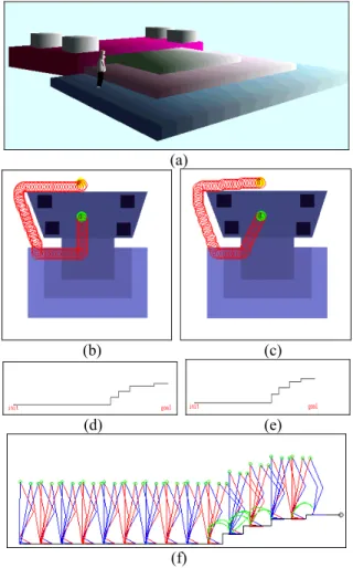
In Figure 6, we show another complete example con-nected to a humanoid model in a 3D workspace (Figure 6(a)). The task for the humanoid is to move from its initial configuration on the ground to the goal configuration on top of the platform as shown in Figure 6(b). The path found in Figure 6(b) is smoothed to the one in Figure 6(c) in a postprocess-ing step. The construction times for the instability map and the reachability map are 60ms and 440ms, respectively. The path in Figure 6(b) is computed in 50ms with a path length of 182. The elevation pro-files for these two paths are shown in Figure 6(d) and 6(e), respectively. The smoothed path is shorter horizontally than the original path. Note that the path of the humanoid is usually perpendicular to the edge of an object. This phenomenon results from an ap-propriate setting on the counter m, which is the
(a) (b)
(c) (d)
(e) (f) Figure 5. Examples of humanoid motions with
maximal number of time steps that we allow the hu-manoid to stay on the unstable boundary region con-tinuously. The smoothed profile is then inputted into a locomotion computation routine to generate a walking motion that can step up stairs without col-liding with the ground as shown in Figure 6(f). This locomotion computation routine is a footstep plan-ning routine that can place the footsteps at appropri-ate location along the path such that the walking lo-comotion does not collide with the ground or the stairs. An efficient kinematics-based approach is used in the locomotion computation routine to flexibly generate the desired motion. There is no guarantee that the footstep planning routines will produce a feasible locomotion plan. If the local planning fails, the failure should be feedback to the global planner to generate another global plan, as shown in Figure 1. However, the complete planning loop is still under development and is beyond the scope of this paper.
5. Conclusion
In this paper, we have described a motion-planning scheme for generating feasible humanoid walking motions on stair-like terrain. The focus has been put on designing a global path planner that can generate a gross motion plan respecting the environmental and the humanoid constraints. With the new problem definition, we modify the Best-First planning algo-rithm to account for user preference on horizontal or vertical distances that a humanoid travels. We have also connected the planner to a locomotion routine to generate collision-free walking motion. We believe that this work will inspire further studies on the in-teresting problem about computing humanoid motion automatically for movie generation or autonomous humanoid robot.
References
[1] N.M. Amato, O.B. Bayazit, L.K. Dale, C. Jones, and D. Vallejo, “OBPRM: An Obstacle-Based PRM for 3D Workspaces,” Robotics: The
Algo-rithmic Perspective, pp.630-637, 1998.
[2] J. Barraquand, L. Kavraki, J.C. Latombe, T.Y. Li, and P. Raghavan, “A Random Sampling Scheme for Path Planning,” Intl. J. of Robotics
Research, 16(6), pp.759-774, Dec. 1997.
[3] J. Barraquand and J. Latombe, “Robot Motion Planning: A Distributed Representation Ap-proach,” Intl J. of Robotics Research, 10:628-649, 1991.
[4] R. A. Brooks,and T. Lozano-Perez, “A subdivi-sion Algoritm in Computer Space for Find-Path with Rotation,” IEEE Trans. on System. Man,
and Cybernetics, vol. 15, pp.224-244, 1985.
[5] Q. Huang, K. Kaneko, et al., “Balance Control of a Biped Robot Combining Off-line Pattern with Real-time Modification,” Proc. of IEEE
Intl. Conf. on Robotics and Automation,
pp.3346-3352, April, 2000.
[6] Y.K. Hwang and N. Ahuja, “Gross Motion Plan-ning – a Survey,” ACM Comp. Surveys, 24(3):219-291, 1992.
[7] L. Kavraki, P.Svestka, J. Latombe, and M. Overmars, “Probabilistic Roadmaps for Fast Path Planning in High-Dimensional Configura-tion Spaces,” IEEE Trans. on Robotics and
Automation, 12:566-580, 1996.
[8] H. Ko and N.I. Badler, “Animating Human Lo-comotion with Inverse Dynamics,” IEEE Transaction on Computer Graphics, 16(2), pp.50-59. 1996.
[9] J. Kuffner, “Goal-Directed Navigation for (a)
(b) (c)
(d) (e)
(f)
Figure 6. Examples of humanoid motions with walking locomotion in a 3D scene
mated Characters Using Real-time Path Plan-ning and Control,” Proc. of CAPTECH’98,
Workshop on Modelling and Motion capture Techniques for Virtual Environments,
Springer-Verlag, 1998.
[10] J. Kuffner, et. al., “Motion Planning for Hu-manoid Robots Under Obstacle and Dynamic Balance Constraints,” Proc. of 2001 IEEE Intl.
Conf. on Robotics and Automation, pp.692-698,
May 2001.
[11] S. M. LaValle, “Rapidly-Exploring Random Trees: A New Tool for Path Planning,” Iowa State University, 1998.
[12] J. Latombe, Robot Motion Planning, Kluwer, Boston, MA, 1991.
[13] T.-Y. Li, J.M. Lien, S.Y. Chiu, and T.H. Yu, “Automatically Generating Virtual Guided Tours,” in Proc. of the Computer Animation '99
Conf., pp.99-106, May 1999.
[14] T.-Y. Li, and H.-K Ting ., “An Intelligent User Interface with Motion Planning for 3D Naviga-tion,” Proc. of the IEEE Virtual Reality 2000
Conf., March 2000.
[15] H. Miura and I. Shimoyama, “Dynanic Walk of
a Biped,” Intl. J. of Robotics Research, pp.60-74, 1984.
[16] J.H. Reif, “Complexity of the Mover's Problem and Generalizations,” Proc. of the 20th IEEE
Symp. on Foundations of Computer Science, pp.
421-427, 1979.
[17] D. Sent and M. H. Overmars, “Motion Planning in Environments with Dangerzones,” Proc. of
2001 IEEE Intl. Conf. on Robotics and Automa-tion, pp.1488-1493, May 2001.
[18] Z. Shiller, K. Yamane, Y. Nakamura, “Planning Motion Patterns of Human Figures Using a Multi-Layered Grid and the Dynamics Filter,”
Proc. of 2001 IEEE Intl. Conf. on Robotics and Automation, pp. 1-8, May 2001.
[19] A. Witkin and Z. Popovic, “Motion Warping,”
Computer Graphics Proceedings,
SIG-GRAPH95, pp.105-108, 1995.
[20] K. Yamane and Y. Nakamura, “Dynamics Fil-ter – Concept and Implementation of On-Line Motion Generator for Human Figures,” Proc. of
IEEE Intl. Conf. on Robotics and Automation,