ORIGINAL ARTICLE
An RFID-based enterprise application integration
framework for real-time management
of dynamic manufacturing processes
Ruey-Shun Chen&Mengru Arthur Tu&Jung-Sing JwoReceived: 6 April 2009 / Accepted: 8 February 2010 / Published online: 18 March 2010 # Springer-Verlag London Limited 2010
Abstract Enterprise application integration (EAI) is an important issue for a company trying to transform itself into a ubiquitous real-time organization. However, traditional techniques for EAI are only suitable for integrating the virtual information among different applications. The chal-lenge of integrating physical objects with corresponding business processes and applications at the right time and location is a critical concern for companies building a real-time enterprise (RTE) information system. In this research, we proposed an EAI framework based on radio frequency identification (RFID) technology. On the basis of this framework, a prototype system is developed to demonstrate the applicability of the framework in a shop floor envi-ronment. This paper also presents a RFID-based standard operation procedure to configure a prototype system for a particular shop floor operation and an operator orientation for performing the corresponding tasks. The findings of this paper demonstrate that the proposed framework is more capable than most current industrial practices in both man-aging dynamic manufacturing processes and in providing real-time visibility of work-in-process information. Using
this framework, an enterprise can easily integrate an RFID-based solution into its IT infrastructure and manufacturing environment to facilitate real-time management of dynamic production operations.
Keywords Radio frequency identification (RFID) . Enterprise application integration (EAI) .
Real-time enterprise (RTE) . Standard operation procedure (SOP)
1 Introduction
Many manufacturing firms are currently facing increasingly severe global competition, a shorter life cycle of new prod-ucts, and changing customer demands. Thus, they must change their business operations and adapt new information systems that can manage dynamic manufacturing activities and take immediate action to resolve any events that disrupt production or cause customer dissatisfaction. In other words, they must re-engineer their current business practi-ces to a real-time enterprise (RTE) operational model. Survival in today’s hypercompetitive environment is en-hanced by employing a model that enables a firm to achieve flexibility in production and quick responsiveness to changing customer demands. The RTE is defined by the Gartner Group as an enterprise that competes by using up-to-date information to progressively eliminate delays to the management and execution of its critical business processes [18]. To achieve this, systems for a real-time enterprise must be“adaptable” to change and “accept change as the process” [19]. Though many technologies may help transform a company to a real-time enterprise, we believe that an enter-prise application integration (EAI) framework with a radio frequency identification (RFID)-based ubiquitous computing R.-S. Chen
Institute of Information Management, China University of Technology, Hsinchu, Taiwan
M. A. Tu (*)
Institute of Information Management, National Chiao Tung University, Hsinchu, Taiwan
e-mail: [email protected] J.-S. Jwo
Department of Computer Science and Information Engineering, Tunghai University,
Taichung, Taiwan
model can provide good guidance for developing a RTE system.
Ubiquitous computing offers many varied applications, but probably its most significant impact is changing the way an enterprise conducts its business [10], and thus, it becomes a good candidate of computing technology for a real-time enterprise. Ubiquitous computing can be com-bined with existing information systems to create a loosely coupled distributed system that can be dynamically located and invoked to accomplish a complex manufacturing task [3, 5]. Issues related to RFID usage in ubiquitous com-puting applications have been widely studied [2]. RFID provides the function of data carriers that can be read and written; thus, it can record the identity and current status of a product as it is being manufactured [31]. Therefore, applying a RFID-based ubiquitous computing model to production systems will help manufacturing companies achieve real-time management of dynamic manufacturing processes.
When using technology and business changes for com-petitive advantage, an enterprise seeks to build new applications upon its existing IT infrastructure. The process of assimilating new applications with different legacy systems is known as EAI [4]. EAI is even more important for a ubiquitous enterprise since it needs to bring the physical and virtual worlds together [9]. Even though methods that enable the implementation of ubiquitous computing applications have been proposed [1,2,6], they cannot effectively support the integration requirements in a ubiquitous and real-time environment. Current EAI tech-nology is most often done with some form of messaging to link heterogeneous systems and operating environments, with an emphasis on maximizing resilience and robustness. However, integrating a new application with legacy systems is a difficult and an expensive task due to the necessity of customizing the connection that ties the two applications. Currently, there are two major techniques, namely, messaging-oriented middleware (MOM) and web services, for EAI [4]. EAI using MOM is an essential technique for integrating intracompany operations. On the other hand, web services offer a new integration model, designed to overcome the constraints of traditional EAI solutions. In the service-oriented architecture (SOA) model, each application in the enterprise acts as a component in a loosely coupled manner [8]. Service interfaces, communications, data transforma-tions, and directory information are all based on open, wide-ly adopted standards.
The above addressed EAI solutions did not take advan-tage of using ubiquitous computing technology to integrate both the physical objects and the virtual information in an enterprise. By utilizing RFID, we propose a new EAI framework that can help a real-time enterprise implement its new integration requirements. An enterprise could naturally
evolve into a ubiquitous organization if it can unobtrusively integrate its current business processes with RFID informa-tion and make the integrated system capable of detecting vital business events in real time and use this information to take proactive actions accordingly.
An alternative tracking technology to RFID is the bar-code, and it has long been used in retailing and manufac-turing industry. Barcode technology has been proven to be effective in controlling BTO/CTO production systems [17]. However, the barcode requires line of sight, cannot support of batch reading, and is easily dirtied or scraped in harsh manufacturing environments. The cost of RFID tags and readers have come down in recent years, and RFID tech-nology has started to replace the barcode in shop floor control systems. Several studies have been conducted on ways to integrate RFID tags in shop floor operations to further reduce human intervention during production processes and optimize production flows [20, 21, 26–28]. In this research, instead of only using message or service exchanging to perform integration for an enterprise, we use RFID to “hook” the physical objects in an enterprise to different business appli-cations that traditionally are not easily integrated.
The rest of this paper is organized as follows: In Section2, we review RFID technology. In Section 3, we describe a software agent approach with respect to the design of our proposed EAI framework. The framework of the proposed system is outlined in Section4. In Section5, we describe the actual implementation of the proposed system. In Section6, we present case studies of the proposed system and RFID-based standard operation procedure (R-SOP). Performance evaluation of the proposed system is discussed in Section7. Finally, Section8draws conclusions.
2 RFID technology for enterprise application integration RFID is an automatic object identification and data col-lection technology that utilizes radio waves [33, 34]. An RFID system consists of hardware, such as RFID tags and readers, and software like RFID middleware. A RFID reader interrogates a RFID tag. The reader has an antenna that emits radio waves, and the tag responds by sending back its data. The middleware software usually runs on ordinary PCs or servers and provides an interface for many sensor technologies, including RFID, thereby achieving cross-platform hardware integration. RFID tags can be roughly categorized into either active or passive types. Active tags are powered by an internal battery, can typically function in a read/write mode, and have longer reading ranges. Passive tags do not rely on an internal power source. Their operating power is obtained from a transceiver. Consequently, passive tags are much lighter and can operate over much longer periods [33,37]. An RFID framework for
ubiquitous computing applications should usually handle data such as location, neighborhood, time, linkage between the physical and virtual world, history, context, name, and address [7].
RFID technology has had a tremendous impact on edu-cation, healthcare, manufacturing, transportation, retailing, services, and even war [38]. In the field of manufacturing, a number of researchers have utilized RFID to improve the core activities of the manufacturing supply chain including production, warehouse and inventory management, distri-bution, and product life cycle management. For example, in production operation, RFID was utilized to bridge the gap between shop floor automation and factory information systems for more effective and efficient factory system integration [20]. The use of RFID was demonstrated in the collection and synchronization of real-time field data from manufacturing workshops where there were walking-workers and fixed-position, flexible assembly lines [21]. For warehouse and inventory management, a RFID-assisted object tracking algorithm and system to track and forecast the movement state of objects in a manufacturing assembly line were developed [36]. Also, inventory management models that rely on RFID data for tracking and dispatching of time-sensitive materials on a shop floor were studied [35]. RFID-based resource management system can help warehouse users handle orders by retrieving and analyzing information from a case-based data warehouse [39]. In distribution-based applications, RFID information is used to optimize product allocations from manufacturers to distrib-utors and retailers [32]. Finally, Parlikad and McFarlane [40] showed that RFID-based product identification can help manage a product’s life cycle and improve product recovery decisions by providing the necessary information associated with the product after its sale.
Currently, few studies have considered the application of RFID to dynamic manufacturing process control or the real-time enterprise operational model. Therefore, in this study, we propose an RFID-based enterprise application integra-tion framework to realize a real-time enterprise operaintegra-tional model capable of managing dynamic manufacturing pro-cesses. In this study, instead of only using message or service exchanging to perform integration in an enterprise, we used RFID to hook the physical objects in an enterprise with applications that traditionally have not been easy to integrate.
3 Agent-oriented approach for managing real-time information
With the introduction of RFID technology to enterprise information systems, demand for a new kind of software system to process the growing influx of RFID data will
begin to rise. The software agent, in this particular situation, becomes a right candidate to take on the new challenge. An agent is an active object which possesses certain capabil-ities to perform tasks and communicates with other agents based on an organizational structure designed to coordinate the accomplishment of tasks [14]. To cope with the dy-namic changing data generated by a RFID system, we define the “software agent” in this paper as a piece of software that continuously monitors the data sources in a global computer network where the information of interest is made available in real-time. When certain signals are detected in the data, the software takes the appropriate action on the user’s behalf [11]. Such “intelligent” autonomous agents potentially become an essential tool, interfacing with multiple sources of data (including RFID data, say, from RFID tags affixed to objects) to extract information and feed processes or parameters necessary for informed and dynamic decision making. The discrete, dynamic, and distributed nature of data and applications require that solutions do not merely respond to requests for data or information but anticipate, adapt, and (support users to) predict. [12]. The architectural design of the software agent can be seen in many articles. Based on various designs of agent-based systems in the literature [13,14,16] and considering the applicability of the proposed EAI framework, the agent architecture in this research has the following basic components:
& Communication Channel: It handles incoming and out-going messages for an agent. Messages might be coming from tag readers, web service, other enterprise systems, and other agents.
& Agent Repository: Each software agent should have its own memory of where various business rules/logic and current/past state information would reside.
& Message Parser: When an agent receives an incoming message from a communication channel, its message parser will analyze its message type and corresponding event lists, delivering them to an event processor to perform appropriate business operations.
& Event Processor: The event processor interprets the decomposed messages delivered from message parser, consults the Agent Repository for business rules/logics, and then undertakes the appropriate action based on the message type/event lists and their corresponding busi-ness rules/logics.
4 RFID-based EAI framework
Based on SOA and the software agent approach, we pro-pose an EAI framework that utilizes RFID tags as the physical connectors integrating the nuts and bolts of the physical objects and the enterprise applications. Figures 1
and2are diagrams that illustrate the architectural design of our proposed EAI framework.
4.1 Architecture of the proposed EAI framework
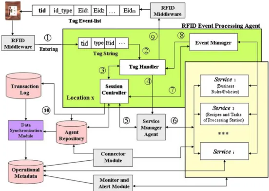
The general EAI framework composes software agents and RFID tags with a specially designed data structure named “event lists,” as shown in Fig.1. The event lists are strings of information occupying a small memory space in a RFID tag. Information can be read from and written into this memory space, thus making the tag an intelligent product
or mobile agent with its own memory. Entering a location equipped with a RFID reader, a tag is “awakened” by the reader and virtually becomes “alive”. This “living object” within a specific time and space can retrieve its past history from its own event lists or Agent Repository, perform tasks through a Service Manager Agent, and receive instructions from the Event Manager regarding the future action plans. The journey will go on to the next time and space. When event handling logic is preloaded in the memory of a RFID tag, processed events become in-memory past events, and unprocessed events become in-memory future events. Fig. 1 EAI framework using
RFID and software agents
The roles of agents and other constitutes in the frame-work are shown in Fig.1and described in detail below: & RFID Middleware: The middleware module is mainly
responsible for managing RFID readers and filtering raw RFID data, providing a logical interface for appli-cation users to perform physical RFID reader manage-ment and low-level raw RFID data handling. A simple RFID event (containing tag content string, timestamp, and location id) is generated by RFID middleware after preprocessing of raw RFID signals. Further RFID event processing is carried out by the RFID Event Processing Agent (REA) in our proposed framework.
& REA: A RFID Event Processing Agent is designed to handle RFID event information and take appropriate action at a workstation. In the following, different functional modules, which constitute the RFID Event Processing Agent, are described.
◼ Tag Handler: The Tag Handler module is respon-sible for the tag read/write process and parsing and analyzing the incoming simple RFID event infor-mation (from RFID middleware). It will convert a simple RFID event into a workpiece processing event if the RFID event is about processing a workpiece. It also facilitates the tag handling process based on location-specific tag processing logic. It usually requires the RFID middleware to facilitate its tag read/write processes.
◼ Session Controller: The Session Controller module primarily performs a session control and data access/ discovery role in the REA. It also provides a data cache for sets of parameter data accepted from a tag handler and location- and/or operation-specific information retrieved from Agent Repository (re-quested by the same tag handler). The Session Controller spawns a new event handling session for a workpiece processing event generated by the Tag Handler. When a workpiece event processing cycle is completed, it synchronizes the processing infor-mation with the Agent Repository and releases the memory resource for use in a computer server. These caching and RFID event session cycle management operations provided by the Session Controller help improve the overall RFID event processing speed and data integrity.
◼ Event Manager: The event manager module is responsible for preparing new events and producing a write or clear instruction for the data of the RFID tag through the tag handler. It retrieves new event information from Agent Repository or receives overwriting event handling instructions from vari-ous services and then prepares the information required by the new event and produces a new
event code containing associated event information. It then requests the RFID tag handler to write the new event code to the corresponding RFID tag. Finally, the event manager module needs to deter-mine next operation processing and procedure unit for a workpiece.
& Service Manager Agent (SMA): The Service manager agent accepts service requests from the REA and invokes external services for the REA. Those services can reside in a machine, a server, or any other device. The SMA can invoke those services through the SOA architecture or directly make function/program calls to those services. After services complete their tasks, the SMA is responsible for collecting the operational results from those services and reporting back to the REA. & Connector Module: The Connector Module is also
responsible for application integration between the frame-work and external applications including enterprise resource planning (ERP) systems and manufacturing execution systems (MES). It receives related interface information such as job orders from the ERP and working orders from the MES, and it also sends related interface information to them. For example, it can retrieve relevant information for initialization of an RFID tagged work-piece from the ERP and the MES. Likewise, it can also retrieve certain information from operational metadata and export them to services that request such information on a specific occasion.
& Monitor and Alert Module: When certain signals or patterns are detected in the operational metadata, this module will obtain real-time process status of workpieces and report process changes to other modules requesting such information. The module is implemented as an in-tegrated part of a web application module in our prototype system, which will be fully discussed in later sections. & Data Synchronization Module: In this module,
extrac-tion, transformaextrac-tion, and loading (ETL) procedures are used to consolidate and transform data from the Agent Repository and Transaction Log into Operational Meta-data. These procedures will first convert RFID events into business events and then consolidate business events with a business process model (e.g., routing information) stored in the Agent Repository to yield contextualized business process events.
& Agent Repository: In the manufacturing environment, this data repository usually resides in the line-control PC for a processing area or a local production line. The fol-lowing types of information are stored:
◼ Mapping information for the RFID reader/antenna and the area/location covered by it
◼ Master data regarding each specific processing area or production line
◼ Recipe-related information of local machine/tools in a processing area or production line
◼ System parameters and other data specific to the local processing area or production line
& Transaction Log: This is an operational data store that keeps not only all the tag transaction data as a tagged item moves from one location to another but also some his-torical information. This data repository can be located in the central system that monitors all the distributed line-control PCs. It can also reside in local line-line-control PCs and then periodically shares its information with the central system.
& Operational Metadata: It can also be called an “opera-tional metadata store”—a special kind of data ware-house that keeps current (near real-time) operational metadata that has been extracted from multiple opera-tional data sources (in this case, a tag activity log and Agent Repository), consolidated and normalized into a complete data model, and made available for query and analysis. We can more easily acquire real-time infor-mation regarding the location of a tagged item with the help of operational metadata.
& Services: Various services encapsulated within SOA. These services can be existing enterprise system func-tions or custom design funcfunc-tions for a specific agent. 4.2 Encoding scheme for RFID tag
The RFID tag’s coding scheme can be seen as part of an ontology model of our proposed EAI framework. Ontology is used for agent’s knowledge sharing and is becoming a crucial element for building a multiagent system. Only what can be represented using ontologies can be repre-sented in agent’s knowledge bases [23]. Recent writings [24] describe a multiagent system that applied ontology and agent technology to construct virtual observatory capabil-ities. RFID and agent-based collaborative mold production system that incorporated the ontology model in its multi-agent system design are good examples of using ontology in agent-based system [25].
The memory’s data structure of a RFID tag attached to a workpiece mainly comprises three main areas as shown on Fig.2(the structure can be extended to include more areas), namely Tag ID denoted as tid, Tag object type and attribute denoted as id_type, and event content denoted as Eid. The reserved flexible area is an optional memory space to capture information not categorized. Except for a tag ID that may reside in tag identification memory, a predefined memory organization by industry standard, the rest of data types are allocated in programmable user memory, a free memory space that allows user-specific data storage, and its
memory organization is user-defined. The details of these data types are explained below:
& Tag ID (tid): The tag ID is a unique code of the RFID tag representing a physical object, and the coding can follow an industry standard (e.g., EPC Global or ISO standards) or be unique to the company.
& Tag object attribute type (id_type): The ID type is used for recording the class of the product and associated information related to the product to facilitate the rapid classification of tagged physical objects. For example, we can define id_types as product or component to discern whether a tag id represents an end product or an assembly component in the manufacturing process. & Event identifier (Eid): Event identifier provides storage
space for recording processing instructions and produc-tion pedigrees for workpieces or products. Each Eid contains either a pointer or encoded information to rep-resent actual routing or service instructions. Each Eid comprises an event header (EH) and an event payload (EP). The EH is used to record various process flags and status information, and the EP is used to store various event-related setting data. These Eids can be either predefined where event handling logic is pre-loaded in the memory of RFID tag or dynamically determined at run time where event handling logic of next stage is written to RFID tag only after a current operation is completed. If the case is static, one simple design scheme for Eid structure will have an EP that contains a recipe code of a processing stage and an EH that contains a status flag indicating whether a corresponding processing stage has been finished or not. Eid lists can form a type of production pedigree that contains the history of events that have taken place for a tagged product. On the other hand, if the case is dynamic, we can make the Eid record the processing results only, like a production pedigree, and store the dynamic part of processing instruction in the reserved block. The prototype system implemented this scheme. Nevertheless, the data structure of the event identifier is not limited to containing only routing or processing instruction. Event identifier can be designed to contain various flags, data types, and coding schemes that provide shared ontology to represent the common definitions that describe tag object characteristics. These Eid lists form event link-lists that can be manip-ulated by RFID Event Processing Agents and Service Manager Agents. These agents must also ascribe the same meaning to the coding scheme of the RFID tag for the effective communication between agents and intelligent products (tagged items) and among agent themselves. We will use the term event lists to represent Eid lists.
Such a RFID tag can be treated as an intelligent product or mobile agent which has the following characteristics [15]:
1. Possesses a unique identification
2. Is capable of communicating effectively with its environment
3. Can retain or store data about itself
4. Deploys a language to display its features, production requirements, etc.
5. Is capable of participating in or making decisions relevant to product’s own destiny
Even though our current tag design cannot satisfy characteristics 2 and 5, we still can make it a mobile agent by making RFID Event Processing Agent assume such a role when it is processing a tagged workpiece. The details of how it is done will be shown when we discuss RFID Event Processing Agent in later sections.
4.3 Agent-based control and RFID event processing model The interactions and information flows among components of the framework used for processing RFID event informa-tion are referred to as event processing steps (EPS), as illustrated by Fig. 3. The details of these interactions and the corresponding event handling logic are described below (these generic event processing steps may be modified for different applications):
& EPS-1: A tagged object (ex. a workpiece) transmits its data to an RFID reader whenever it enters the reading
range of a reader’s antenna. The RFID reader then passes these data to the RFID Middleware which constantly monitors several reader devices. The RFID Middleware, upon receiving the raw tagged data, performs data filtering and obtains the tag ID, the product type and attributes, and the event content from the RFID reader. This middleware then relays them to the target Tag Handler module. In a case where the tag data need to be parsed, the Tag Handler module must also incorporate a data parser to perform the parsing operation.
& EPS-2: The Tag Handler is coupled to the RFID Middleware, and the tag data can either be sent to the Tag Handler by the Middleware or be cached in the Middleware first and then retrieved by Tag Handler when it has the capacity to process more tag data (in the case of processing multiple tags).
& EPS-3: After receiving tag data, the Tag Handler immediately parses and analyzes that data and generates a new RFID event (ex. a workpiece processing event). The Tag Handler then invokes Session Controller to spawn a new event handling session for that RFID event and transmits associated parameters (information such as tag ID, ID type, and Eid) to the Session Controller. & EPS-4: The Session Controller creates an event
han-dling session and assigns a session memory for it. We prefer to create a session memory in persistent storage to avoid data loss and preserve data integrity during the entire lifecycle of event handling session. The Session Controller then obtains the associated information with respect to a workpiece as well as location- and/or Fig. 3 Event processing and
information flows of the proposed EAI framework
operation-specific information from Agent Repository using the parameters passed from the tag handler and then caches these data in its memory.
& EPS-5: The Session Controller sends key parameters regarding a tagged object back to the Tag handler for further determination and processing.
& EPS-6: Using the parameters obtained from the Session Controller, the Tag Handler compares and analyzes tag ID and event parameters to determine whether an event can be processed at this location and at this time. If the result is positive, the Tag Handler sends a notification with associated parameter data to the Service Manager Agent to process the event; otherwise, it informs the Service Manager Agent to handle the exception and to display error message and relevant correcting informa-tion for the user.
& EPS-7: The Service Manager Agent, upon receiving an event processing notification and associated parameters from the Tag Handler, retrieves event process logic or recipe information either from the Agent Repository or External Sources. Alternatively, if detailed event data are predefined and preloaded in the tag memory bank during the initialization of the tagged object, the Service Manager Agent performs its operation directly in accordance with the associated setting data and instruc-tions associated with the tag sent from the tag handler. The Service Manager Agent then transmits the event process logic or recipe information to the external systems such as processing machines or MES and drives the automatic process flow (either directly drives or communicates with the external system through network service or waits for a manual process). & EPS-8: When external process/operation is completed,
the external processing information is sent back to the Service Manager Agent by the external system. & EPS-9: The service Manager Agent then relays the
external processing information to the Session Controller. & EPS-10: The Session Controller registered the external processing information in its cache memory and sends a completion notice and the associated parameters to the Event Manager.
& EPS-11: The Event Manager reads the associated event process flow information from the Agent Repository (through the Session Controller) in accordance with the associated parameters, and it obtains the latest informa-tion regarding the status of an intelligent product (tagged object) and its environment (such as resource or routing information). Finally, data comparison and computing are performed in accordance with the information, and the associated information of the event to be completed in the next stage of the tag (workpiece) is obtained. New event information (e.g., ID type and Eid) is generated. Alternately, if the Eid is predefined
and preloaded in the tag during the initialization of the tagged object, then the Event Manager directly reads out the new event information from the Eid lists residing in the tag memory. Finally, the Event Manager transmits the new event information to the Tag Handler. & EPS-12: The Tag Handler writes the new event into the RFID tag (i.e., the corresponding tagged object/work-piece) through the RFID middleware and RFID reader, and it also updates the associated parameters of the current event. Additionally, the Event Manager may request the Tag Handler to obtain a workpiece’s tag id from Middleware and consult with the Session Con-troller whether that id is the same with the one currently cached in session. This extra procedure can help RFID Event Processing Agent to make sure it is working on the same workpiece and thus can avoid updating in-formation to a wrong workpiece.
& EPS-13: After the tag event is written successfully, the Tag Handler informs the Session Controller so that the associated data registered in its cache memory is written to the system database (Agent Repository and Transac-tion Log), thus releasing the corresponding cached event data associated with the workpiece from the memory of the Session Controller during this event handling session.
5 Prototyping of the proposed EAI framework
In order to prove the applicability and usefulness of the proposed EAI framework, we developed a prototype to validate the design of the framework. Based on the scenario of semiconductor testing processes, the prototype system is applied on a pilot production site of a local IC testing firm to provide a proof of concept demonstration. It helps firms evaluate the feasibility of possible future implementation of such system and its improving effect on manufacturing process control and product quality. This pilot study was conducted for a leading semiconductor packaging and testing contract manufacture in Taiwan.
5.1 System infrastructure
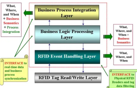
The processing of the real-time RFID data can be divided into four layers, as illustrated in Fig. 4. This layered information processing architecture decouples different RFID event handling phases where each phase requires a different set of data processing logic and techniques. This research constructs the prototype of the proposed EAI framework based on such layered architecture and a multitiered, web-based infrastructure to facilitate real-time RFID information processing. Figure 5 depicts the infor-mation infrastructure of the proposed system. The architec-ture consists of three parts—the hardware device that
includes passive RFID Tag and RFID Reader with Antenna. The RFID Middleware provides a logical control interface to manage physical RFID readers and preprocessing large volume of raw RFID data. Finally, the RFID application contains most of the software components and application modules and a system database. We deployed RFID Mid-dleware system to a small Intel-based server (system server #1) and RFID application and database to another server (system server #2). The RFID readers are connected to the system server #1 through LAN system, and the RFID application communicates with RFID middleware through Internet system. Mapping the information infrastructure of the prototype system (Fig. 5) to the layered RFID infor-mation processing architecture (Fig. 4), we can see that RFID readers and tags correspond to the bottom layer of the
processing architecture; RFID Middleware corresponds to the RFID Event Handling Layer, and the RFID application implements both Business Logic Processing and Business Process Integration Layers. Section5.2will discuss the com-ponents of the RFID Middleware and RFID application.
The development environment of the prototype system is briefly described below:
& Operating Systems: server: Window XP, client: Window XP & Database: SQL Server
& Programming language: Java technology stack (JSP, JDBC, Java Beans…,etc.)
& Application Server: Tomcat
& RFID Tag: EPC C1Gen 2 passive RFID Tag & RFID Reader: AWID UHF RFID Reader Fig. 4 The layered RFID
information processing architecture
Fig. 5 Prototype system’s infrastructure
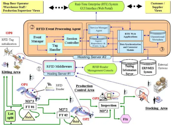
5.2 Design and implementation of system components A prototype of the proposed EAI framework was implemen-ted as a computer integraimplemen-ted manufacturing system (Fig.6) used in a shop floor environment. The system was designed to facilitate dynamic control of semiconductor testing pro-cesses and real-time tracking and tracing of these processing flows. Three main objectives of the system are to provide better process visibility, to better handle process changes, and to enhance quality of testing service. As shown in Fig.6, we divided the prototype system into three parts. Each part has its own components and is implemented separately. 1. RFID Middleware: RFID Middleware is an application
that directly controls the physical RFID readers and performs RFID raw data preprocessing. Built upon the middleware application is a RFID reader management console, which is a Java client application providing graphics user interfaces for configuring reader settings and monitoring reader activities. The RFID reader management console is shown in Fig. 7. To cope with different requirements from both manufacturing and logistic operations, we incorporated control mechanisms to allow the Middleware to handle both cases. In the “Modify Reader” function of the Middleware, users can set RFID readers to writing mode (single tag), single tag reading mode, and multiple tags reading mode. Single tag reading mode is designed to facilitate manufacturing operations for readers deployed at workstations. If more
than one RFID tag is detected by reader at a work-station’s input/output buffer, the RFID reader manage-ment console will prompt operator with warning message. On the other hand, multiple tags reading mode is designed to accommodate logistic operations for readers deployed at dock doors where Middleware must capture all tags passing through the door. These specialized features make our RFID Middleware flexible enough to meet different needs of manufacturing and logistic tasks.
2. REA: Three functional modules of the REA are imple-mented in Java, each with its own execution logic as described in Section 4.1. These modules help REA perform various tasks. For example, the agent can use event validation algorithms implemented in the Tag Handler module to validate the testing process sequence and the testing process logic of a semiconductor testing lot; decision-making algorithms implemented in Event Manager can help the agent schedule new task for a semiconductor testing lot. Details of these algorithms will be discussed in later sections. In addition, a variant of the standard Tag Handler module was created to handle batch reading of workpieces in a queuing or buffer area. This specialized Tag Handler submodule only performs item counting and bypasses other com-plex event handling processes of the standard Tag Handler. We called this a pure tag logging mode, and the tag handler of a REA can be configured for standard mode or pure tag logging mode.
Fig. 6 System architecture of the prototype system
3. RFID Integration Modules: This portion of system takes care of shared system processes that support the RFID event processing agent. The data mapping and synchronization programs are responsible for most data intensive operations like data extraction, consolidation, and synchronization. For example, retrieved master data and other reference information from external data sources like the ERP or MES (manufacturing execution system) are consolidated, synchronized, and finally stored as normalized information in the Agent Repos-itory. The RTE web application module is designed to support front-end, user interface operations of the web portal. The RTE web application module may also accept requests from the Service Manager Agent and prompt users to perform certain tasks accordingly. The RTE web application module incorporates monitoring mechanisms which constantly retrieve workpiece pro-cess changing information from Operational Metadata and reflect such information on the web portal as shown in Fig.6. Internal and external system users can access a unified web portal with different levels of user privileges and roles. Lastly, the Service Manager Agent is implemented as a service broker for the RFID event processing agent. The service broker acts like a mediator or communicator between a RFID event processing agent and any external services that may dwell in a machine, a server, or other device. The Service manager agent is able to service requests from multiple RFID event processing agents.
Another issue for system implementation is the design of RFID tag coding scheme. The tag data structure is designed based on a company’s specific requirements as shown in Fig.8. Based on the discussion of the encoding scheme for a RFID tag in Section4, we determined that our prototype has dynamic processing flow, and the tag data structure is designed accordingly. We made the Eid record the process-ing results which served as a production pedigree where the EH of each Eid contained a pass/fail status flag indicating whether a corresponding processing stage has been suc-cessfully executed or not, followed by an EP containing operation code and workstation code of that processing stage. For the dynamic part of processing instructions, we stored the next operation code and workstation code in the reserved block. Also stored in the reserved block were total chip and bad chip quantities. The order of the Eids thus forms a production pedigree of semiconductor testing for a tagged lot container. Finally, part of the prototype system is implemented based on a R-SOP. The R-SOP will be discussed in the following sections.
6 Case study
The prototype system simulates a shop floor operation in a semiconductor packaging and testing environment with build to order strategy. The simplified manufacturing pro-cesses and their material and information flow are shown in Fig. 6. The facility layout in the pilot production site Fig. 7 The RFID reader
consists of three types of facility items: kitting area, pro-duction control area, and stocking area. The kitting area is set up for material preprocessing and the stocking area for storing finished products. The labels numbered OP0∼OP3 are routing/processing steps for a tagged workpiece (in this case, a chip container). Several workstations are deployed to simulate actual semiconductor testing processes. These are grouped by three different type of operations (OP1∼OP3) where final test FT1 operation has three workstations and FT2 and inspection operations each has two workstations,
respectively. RFID readers are deployed at the check-in buffer and the check-out buffer of each workstation as shown in Fig. 9 and on top of a dock door as showed in Fig.10. Using one reader with two antennas positioned inside and outside of a dock door, we can distinguish incoming and outgoing tagged objects. Each check-out buffer can also serve as a quality control station where a testing lot that does not pass the testing criteria can be stopped from flowing to the next production phase, and remedy actions can proceed immediately.
Fig. 8 RFID tag coding scheme of the prototype system
Fig. 9 Mechanism of RFID-based SOP for scenario 1
6.1 Scenario 1: RFID-based standard operation procedure for shop floor operation
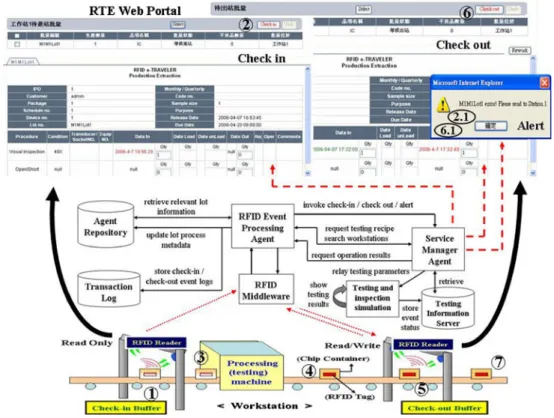
The system architecture shown in Fig. 6 illustrates an operation scenario of semiconductor testing for our pilot research. When receiving customer orders, the company’s ERP system generates a corresponding job order and transfers it to the MES system. Then, the MES system transforms the job order into working orders and notifies our prototype system of the arrival of new working orders. The prototype system then extracts the working orders from the MES database and consolidates the information into the Agent Repository. A production supervisor can release the working orders from the web portal. The manufacturing processes are initiated in the preprocessing stage, and relevant information is written to the RFID tags attached to an IC chip containers at this stage. A RFID tag attached to an IC chip container contains several chips belonging to a single testing lot. Information written to the tag follows the coding scheme revealed in Fig.8. Initially, the bad chip quantity is set to zero, the next operation code is set to FT01, the workstation code of next operation is set to workstation 1 of FT01, and the event logging block is set to null. When a lot completes its initialization process, its information is relayed to the first workstation, and shop floor operators immediately receive this information on the web portal. Additionally, the required parts or materials are also prepared in the Kitting Area and will be delivered to workstation on demand. As a lot moves into a workstation, operators will perform a serious of shop floor operations as shown in Fig. 9
(numbered from 1 to 7). We propose a R-SOP to model these sequences of actions as a discrete event system. The R-SOP is used to configure the prototype system for a particular shop floor operation and guide operators to correctly perform tasks for the operation. The R-SOP of Fig. 9 displays a semiconductor testing process used in our research. Tradi-tionally, SOP are written in documents to serve as guidelines for operators to efficiently perform tasks without errors. Likewise, R-SOPs are designed to correctly and efficiently guide operators carrying out tasks that involve RFID technologies in the operational processes. Thus, R-SOPs must be customized to meet different requirements for each unique business case. In our case study, the R-SOP starts when triggered by the RFID reader detecting a lot (chip container) being placed on the check-in buffer of a work-station and ends after tag event parameters are written to the container’s RFID chip. The mechanism to support the R-SOP is based on our proposed RFID-based EAI framework. Figure9 shows the R-SOP of a typical operational sce-nario in our prototype system. The R-SOP involves fol-lowing steps.
1. A RFID tagged IC chip container being placed on the check-in buffer of a workstation (ex. FT01) and
detected by the motion sensor of the buffer: The motion sensor then triggers the RFID middleware to launch the RFID reader to retrieve lot information from the RFID tag attached on the chip container. RFID middleware first conducts RFID signal preprocessing to generate a raw event, or a string holding parameters from both the container’s tag and the RFID reader. Middleware then switches the reader from reading mode to sleep mode and relays raw event to the REA. The REA first parses the raw event to obtain relevant parameters and then performs a lot validation based on obtained parameters and relevant lot information retrieved from Agent Re-pository. Detailed lot validation activities will be ana-lyzed in the next section.
2. If a lot passes the validation, the REA will invoke a check-in process as shown in Fig.9. Operators simply click the check-in button to complete the check-in process.
2.1. On the other hand, if a lot does not pass the validation, an alert message will be prompted to instruct operator to move the wrong chip container out of the check-in buffer.
3. If a lot passes the validation, a field operator or engineer will take the chip container to processing/testing equip-ment and start performing the testing operation. In our lab environment, a separate computer loaded with sim-ulated testing and inspection programs is used to mimic the real testing operation. The testing results are shown on this computer, and the event status corresponding to the testing results are relayed and stored in a testing information server.
4. Once the testing is completed, the operator must move the chip container from the testing equipment to the check-out buffer.
5. The operator places the RFID tagged IC chip container on the check-out buffer of the same workstation, and the motion sensor of the buffer will detect the presence of a chip container. The motion sensor then triggers the RFID middleware to launch the RFID reader to retrieve lot information from the RFID tag attached to the chip container. After the reading is completed, the RFID middleware obtains raw event and switches the reader from reading mode to sleep mode. Middleware then relays the raw event to the REA. The REA parses the raw event to acquire the unique identification of the container. Based on the container ID, the REA verifies the lot on the check-out buffer to make sure it is the same lot that just completed testing in the same workstation. 6. Once the lot passes the validation, it triggers the REA to
perform a serious of postprocessing activities, including scheduling a new task for the lot and updating relevant information in the system database and container’s tag.
Finally, the REA will invoke a check-out process as shown in Fig. 9. Operators simply click the check-out button to complete the check-out process.
6.1. On the other hand, if a lot does not pass the validation, an alert message will be prompted to instruct operators to replace the wrong container with the right one on the check-out buffer.
7. After confirming the check-out state, operators will take chip container out of the check-out buffer. This concludes the R-SOP portion of this scenario.
As a chip container comes off the check-out point, the system will relay its lot number to the next workstation, and this process will continue until a lot completes all necessary operations.
Main duties performed by the REA to facilitate a RFID-based SOP for shop floor operation (scenario 1) are sum-marized in the following tables (Tables1,2,3,4,5). Both procedures and algorithms are elucidated in the tables using pseudo code.
6.2 Scenario 2: Real-time lot process visualization
4. RFID has proved to be very effective in facilitating real-time tracking and management of logistic processes. A dynamic logistics process knowledge-based system [29] to automatically identify various logistics process status
in real time and perform process logic checking/ reasoning is a good example. Unlike the RFID-based SOP case where REA must handle complex RFID event processing, most pure logistic events like workpieces passing through a RFID-based dock door only require the REA to simply log their entrance/exit events, as shown in Fig.10. Thus, we configured another instance of a REA with its tag handler set to pure tag logging mode. This REA is constantly updating logistic process status into a Transaction Log after receiving tag transaction events relayed from RFID middleware. Besides the logistic events, the Transaction Log also stores the manufacturing process status of each tagged chip container (lot) as it completes its check-in and check-out operations as mentioned in previous section. The Data Synchronization Module then performs ETL processing to convert data in Transaction Log into Operational Metadata at every preset time interval. Finally, the RTE web application can retrieve real-time lot process information and present it to application users through the RTE web portal. These steps of visualizing lot processes are illustrated in Fig. 10. Figure 10 also demonstrates scenarios where custom orders are corre-lated to the lot status. The lot status on the portal is changed in near real-time when an underlying tagged chip container (corresponding to the same lot) is physically being moved from one place to another. Table 1 Task 1 of REA to validate testing process sequence
7 Performance evaluation
The surveyed company currently uses paper travelers (run cards) with bar code labels for tracking and identifying the thousands of chip containers moving around its testing facility each day. Tracking and tracing its manufacturing process information involves human intervention that often causes many errors and information delay. These problems further affect its process quality control. In our proof of concept pilot research, we found that the overall manufac-turing process monitoring and control was improved by the application of RFID technology and our prototype system. Table6presents a comparison of information tracking capa-bility between that company’s current tracking technology
and our proposed one. It seems obvious that RFID technology can significantly close the gaps between product flow and information flow. A RFID-based material flow control system developed for an IC assembly firm suggested that RFID contributes significant improvements to the wafer-receiving process and the inventory transaction process in terms of reducing man-made errors and labor costs [30]. We also obtain similar performance results from our prototype system. In addition to improved tracking and tracing capa-bility, the prototype system greatly enhanced the quality of the firm’s testing service as our proposed R-SOP helped shop floor operators correctly handle dynamic testing pro-cedures and thus greatly reduce operational errors. With the help of our proposed solution, field operators can correctly Table 2 Task 2 of REA to validate testing process logic
resolve shop floor problems before they propagate to the next testing process.
8 Conclusion
One of the major trends in globalization is the use of mass-customization production and a ubiquitous and real-time
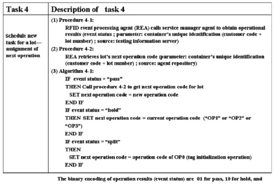
organization in manufacturing enterprises. To become a RTE, it is necessary to use information technology to integrate related information and physical objects at different times and different locations. The proposed EAI framework and prototype system can serve as a reference model for a surveyed company. The framework can also be applied to many other semiconductor manufacturers, helping them to build their next generation of virtual fabs Table 4 Task 4 of REA to schedule task assignment of next operation
(VF; a VF is a foundry that provides integrated manufac-turing services to its customers as if this foundry fab were the customer’s own fab and has been adopted by leading semiconductor manufactures like TSMC and UMC [22]).
Despite the apparent benefits of RFID, environmental interference of RFID signals, especially metal in the manu-facturing environment, is still one of the major challenges of UHF RFID technology. Current ways around this issue include the purchase antimetal tags and installation of more antennas to capture a tag signal from different angles. These increase implementation costs. Thus, further research and development of better tag data preprocessing and RFID event generation algorithms for Tag Handler are recom-mended to help the prototype system realize its best poten-tial when applied to a harsh shop floor environment.
In summary, this study makes the following contribu-tions to improving the traceability, visibility, and manage-ability of dynamic manufacturing processes.
& We have proposed a RFID-based EAI framework for tracking and controlling the dynamic manufacturing pro-cess flow.
& On the basis of the framework, we implemented an integrated prototype system that consists of RFID mid-dleware and a shop floor control and monitoring in-formation system to process RFID data in real time. & The proposed framework can markedly improve the
manufacturing process and quality control.
& The findings of this study reveal that the prototype system can provide both the shop floor operators and Fig. 10 Real-time product
status information keeps internal and external users informed
Table 6 Comparison of manufacturing process tracking between two information systems
Criteria Barcode- and run card-based (paper travelers) tracking system RFID-based tracking system Convenience Requires line of sight scan Automatic scan without line of sight Efficiency Cannot support batch reading Can read multiple tags at once
Accuracy Susceptible to misreads and human error Reduced human error and misreads improves data accuracy Traceability Limited traceability. Some harsh manufacturing processes
(like baking) make barcode tacking impossible
Allows detailed tracking and tracing of process status, inputs/outputs, and the time that each processing step was performed
Speed Process information not in real-time Real-time process information Reliability Barcode are easily dirtied or scraped in harsh
manufacturing environment
RFID tag can survived harsh environment like dirty or high temperature
Automation Need more human labor to collect and track process data Replace or reduce human labor in data collection and tracking Information Limited process information Vast amount of detailed process information
the production supervisor with real-time production process information, helping them to respond to the status of the production line in real time and make better decisions when handling production events.
References
1. Arregui D, Fernstrom C, Pacull F, Rondeau G, Willamowski JS (2003) Middleware for ubiquitous applications. In: Proceedings of smart objects conference 2003. Grenoble, France, pp 15–17 2. Floerkemeier C, Lampe M (2004) Issues with RFID usage in
ubiq-uitous computing applications. Lect Notes Comput Sci 3001:188–193 3. Yamaguchi A, Ohashi M, Murakami H (2005) Autonomous decentralized control in ubiquitous computing. IEICE Trans Commun E88-B(12):4421–4426
4. Gorton I, Liu A (2004) Architectures and technologies for enterprise application integration. In: Proceedings of 26th inter-national conference on software engineering, Edinburgh, pp 726– 727
5. Kotorov R (2002) Ubiquitous organization: organizational design for e-CRM. Bus Process Manag J 8(3):218–232
6. Langheinrich M, Mattern R, Romer K, Vogt H (2000) First steps towards an event-based infrastructure for smart things. Ubiquitous Computing Workshop at PACT, Philadelphia, pp 1–13
7. Römer K, Schoch T, Mattern F, Dübendorfer T (2003) Smart identification frameworks for ubiquitous computing applications. In: Proceedings of the 1st IEEE international conference on pervasive computing and communications, pp 253–262
8. Stojanovic Z, Dahanayake A, Sol H (2004) Modeling and design of service-oriented architecture. In: IEEE International Conference on Systems, Man and Cybernetics, pp 4147–4152
9. Want R, Fishkin K, Gujar A, Harrison B (1999) Bridging physical and virtual worlds with electronic tags. In: Proceedings of ACM CHI, Pittsburgh, pp 15–20
10. Weiser M (1991) The computer for the twenty-first century. Sci Am 265(3):94–104
11. Kalakota R, Stallaert J, Whinston AB (1995) Implementing real-time supply chain optimization systems. In: Proceedings of the Conference on Supply Chain Management, Hong Kong 12. Datta Shoumen (2003) Adapting decisions, optimizing facts and
predicting figures. In: MIT forum for supply chain innovation. Working Paper, First Draft
13. Swaminathan JM, Smith SF, Sadeh NM (1998) Modeling Supply chain dynamics: a multiagent approach. Decis Sci 29(3):607–632 14. Lin FR, Tan GW, Shaw MJ (1998) Modeling supply-chain networks by a multi-agent system. In: IEEE proc. thirty-first annual Hawaii international conference on system science, pp 05–114 15. McFarlane Duncan, Sarma Sanjay, Chirn Jin Lung, Wong CY,
Ashton Kevin (2002) The intelligent product in manufacturing control. Journal of EAIA
16. Jeng J-J, Schiefer J, Chang H (2003) an agent-based architecture for analyzing business processes of real-time enterprises. In: IEEE proc. enterprise distributed object computing conference, pp 86–97 17. Chen R, Lu K, Yu S, Tzeng H, Chen C (2003) A case study in the
design of BTO/CTO shop floor control system. Inf Manage 41:25–37
18. Kuhlin Bernd, Thielmann Heinz (2005) I&C technologies for a real-time enterprise. The practical real-time enterprise. Springer, Berlin, pp 201–235
19. Khosla V, Pal M (2002) Real time enterprises, a continuous migration approach. Inf Knowl Syst Manag 3(1):53–79
20. Qiy RG (2007) RFID-enabled automation in support of factory integration. Robot Comput Integrated Manuf 23:677–683 21. Huang GQ, Zang YF, Jiang PY (2006) RFID-based wireless
manufacturing for walking-worker assembly islands with fixed-position layouts. Robot Comput Integrated Manuf 23(4):469–477 22. Sua R, Guoa R, Chang S (2005) Virtual fab: an enabling frame-work and dynamic manufacturing service provision mechanism. Inf Manage 42:329–348
23. Obitko M, Marik V (2002) Ontologies for multi-agent systems in manufacturing domain. In: Proceedings of IEEE 13th international workshop on database and expert systems applications, DEXA 24. Chen R, Chen D (2008) Apply ontology and agent technology to
construct virtual observatory. Expert Syst Appl 34:2019–2028 25. Trappey AJC, Lu T-H, Fu L-D (2007) Development of an
intelligent agent system for collaborative mold production with RFID technology. Robot Comput Integrated Manuf 25:42–56 26. Huang George Q, Zhang YF, Jiang PY (2008) RFID-based
wireless manufacturing for real-time management of job shop WIP inventories. Int J Adv Manuf Technol 36:752–764 27. Shouqin Z, Weiqing L, Zhongxiao P (2007) An RFID-based
remote monitoring system for enterprise internal production management. Int J Adv Manuf Technol 33:837–844
28. Martyn F, Duncan McFarlane, Alan T, Dennis J, Andrew L (2004) Evaluating a holonic packing cell. Lect Notes Comput Sci 2744:1087
29. Chow Harry KH, Choy KL, Lee WB (2007) A dynamic logistics process knowledge-based system—an RFID multi-agent approach. Knowl-Based Syst 20:357–372
30. Liu C-M, Chen LS, Romanowski RM (2008) An electronic material flow system for improving production efficiency in integrated-circuit assembly industry. Int J Adv Manuf Technol 42 (3–4):348–362
31. Doerr KH, Gates WR, Mutty JE (2006) A hybrid approach to the valuation of RFID/MEMS technology applied to ordnance inventory. Int J Prod Econ 103(2):726–741
32. Dong L, Dennis K, Paul D (2006) Dynamic planning with a wireless product identification technology in food supply chains. Int J Adv Manuf Technol 30:938–944
33. Paret D (2005) RFID and contactless smart card applications. Wiley, New York
34. Tanaka K, Kimuro Y, Yamano K, Hirayama M, Kondo E, Matsumoto M (2007) A supervised learning approach to robot localization using a short-range RFID sensor. IEICE Trans Inf Syst E90-D(11):1762–1771
35. Mills-Harris MD, Soylemezoglu A, Saygin C (2007) Adaptive inventory management using RFID data. Int J Adv Manuf Technol 32:1045–1051
36. Jiahao W, Zongwei L, Wong Edward C (2010) RFID-enabled tracking in flexible assembly line. Int J Adv Manuf Technol 46:351–360
37. Finkenzeller K (2003) RFID handbook: fundamentals and applications in contactless smart cards and identification. Wiley, New York
38. Gunasekaran A, Ngai EWT, McGaughey RE (2006) Information technology and systems justification: a review for research and applications. Eur J Oper Res 173(3):957–983
39. Chow HKH, Choy KL, Lee WB, Lau KC (2006) Design of a RFID case-based resource management system for warehouse operations. Expert Syst Appl 30(4):561–576
40. Parlikad AK, McFarlane D (2007) RFID-based product information in end-of-life decision making. Control Eng Pract 15(11):1348–1363