行政院國家科學委員會補助專題研究計畫成果報告
※※※※※※※※※※※※※※※※※※※※※※※※※
※ ※
※
虛擬實境中結合幾何與影像顯像技術之研究(I)
※
※
Hybrid Rendering Techniques for Virtual Reality (I)
※
※
※
※※※※※※※※※※※※※※※※※※※※※※※※※
計畫類別:
þ
個別型計畫
□整合型計畫
計畫編號:NSC89-2218-E-009-013
執行期間:
89 年
8 月
1 日至
90 年
7 月
31 日
計畫主持人:莊榮宏
共同主持人:
本成果報告包括以下應繳交之附件:
□赴國外出差或研習心得報告一份
□赴大陸地區出差或研習心得報告一份
□出席國際學術會議心得報告及發表之論文各一份
□國際合作研究計畫國外研究報告書一份
執行單位:
中
華
民
國
90 年
11 月
27 日
行政院國家科學委員會專題研究計畫成果報告
虛擬實境中結合幾何與影像顯像技術之研究
Pr epar ation of NSC Pr oject Repor ts
計畫編號:NSC 89-2218-E-009-013
執行期限:89 年 8 月 1 日至 90 年 7 月 31 日
主持人:莊榮宏 執行機構及單位名稱
共同主持人:xxxxxx 執行機構及單位名稱
計畫參與人員:xxxxxx 執行機構及單位名稱
1 中文摘要 本研究計畫主要是研究結合 3D 幾何式與 2D 影像 式顯像技術的優點,並且利用空間分割、影像曲化等 技術,發展出一顯像時間能與場景複雜度較無關的虛 擬實境瀏覽系統。整個系統將分前置處理與執行兩階 段,前置處理階段首先將整個場景作雙層蜂巢式的空 間分割成為正六邊形的影像與瀏覽子空間,且每一瀏 覽子空間對應一個影像子空間,而且有相同的中心 點。再對每一個影像子空間,以其中心當作視點,六 個邊面為視窗,分別產生六張快取影像,並且將深度 值也一併儲存,最後將深度快取影像作狄勞尼三角化 處理,以得到深度貼圖網格。執行階段則是瀏覽時整 合影像子空間內幾何式顯像與影像子空間外影像式 顯像的結果。對於空間外的場景利用深度快取影像與 深度貼圖網格經過影像曲化與重新投影的運算,代替 場景資料進行影像式顯像,而對於子空間內的幾何物 體則選擇適當精細度的漸進式模型,配合可見性裁切 決定出最後的幾何資料供顯像系統進行幾何式顯像。 關鍵詞:虛擬實境、影像快取、瀏覽、影像式顯像、 整合式顯像 Abstr actIn this project, we propose a hybrid rendering scheme that combines geometry-based and image-based rendering techniques and have efficiency relatively independent of the scene complexity. The scheme has two stages. In the preprocessing stage, the x-y plane of a 3D scene is partitioned into equal-sized hexagonal cells, called navigation cells, each of which is associated with a larger image cell that has an identical center. Each side face of the image cell will be stored a cached image with depth that is obtained by rendering the scene using the cell’s center as the center of projection and the side face as the window. The depth mesh of the cached image will be obtained by triangulating cached image using depth. In the run-time stage, when the participant navigates inside a navigation cell, objects outside the corresponding image cell will be rendered by warping and re-projecting depth mesh with cached texture image and objects inside the image cell will be rendered by using meshes with appropriate resolution.
Keywor ds: Virtual Reality, Image Caching, Navigation,
Image-Based Rendering, Hybrid Rendering
2 INTRODUCTION
As the Amdal’s law, we can imagine that we will have more and more powerful graphics accelerator in the near future. But we will always have greater expectation on performance and quality for visual applications. In last decades, many techniques have been proposed on the reduction of polygon count and preserving visual realism. For examples, visibility clipping, visibility culling and level-of-detailmodeling, and more recently,
view interpolation, image caching, portal texture, and
image-based rendering.
It is well known that the image-based rendering has efficiency that is independent on scene complexity and could easily produce photo-realistic images. It has, however, very limited viewing degree of freedom. On the contrary, traditional geometry-based rendering has high viewing degree of freedom and accelerated by graphics hardware, but it’s rendering time is dependent on the scene complexity. In this project, we propose a hybrid rendering scheme that combines geometry- and image-based rendering technique to take advantage of both. The aim is to be able to render complex scenes at interactive and almost constant frame rate while still able to achieve good visual realism. In the pre-processing of our scheme, the x-y plane of a 3D scene is partitioned into equal-sized hexagonal navigation cells, each of which is associated with a larger image cell that has an identical center. Each side face of the image cell will be stored a cached image with depth that is obtained by rendering the scene using the cell’s center as the center of projection and the side face as the window. The depth mesh of the cached image will be obtained by triangulating cached image using depth. In the run-time stage, when the participant navigates inside a navigation cell, objects outside the corresponding image cell will be rendered by warping and re-projecting depth mesh using the proposed hardware accelerated projective-alike texture-mapping
and objects inside the image cell will be rendered by using meshes with appropriate resolution. The loading time of neighboring cell data will be amortized to several inside-cell frames.
parallax problem but also the gap (crack) problem resulting from resolution change. It is also capable of reducing popping effects due to cell-to-cell, image-to-geometry, and geometry-to-image transition.
3 RELATED WORK
View frustum culling that prevents the objects that are outside the view volume from being sent to the rendering pipeline is the basic visibility culling. Several methods have been proposed that further cull out polygons that are occluded by others. There include occluding culling usingshadow frusta [7], hierarchical z-buffer [4], and hierarchical occlusion map [17]. Moreover, level-of-detail modeling (e.g., edge collapsing [6], vertex clustering [9], vertex decimation
[11], and progressive mesh [5, 16]) has been very useful to further reduce the number of polygon that are inside the view frustum and visible.
Geometry-based rendering based on visibility culling and LOD modeling alone usually cannot meet interactive requirement for very complex scenes. Image-based rendering (IBR) has been a well known alternative. IBR takes parallax into account, and renders a scene by interpolating neighboring reference views [2, 8, 12]. IBR has complexity that is independent on the scene complexity, and can model natural scenes using photographs, but often constrained by limited viewing degree of freedom. IBR in general has problems like folding, gap, and hole. Layered depth image (LDI) [14] is a good try to eliminate hole problems due to visibility change. LDI structure is more compact in the sense that redundant information has been reduced when several neighboring reference images are composed into a LDI.
Hierarchical image caching proposed in [13, 10] is the first approach that combines geometry-based and image-based rendering aiming to achieve an interactive frame rate for complex static scenes. The cached texture possesses no depth information and has to be re-generated when the error due to parallax exceeds a user-specified tolerance. The image simplification schemes proposed in [3, 15] is another kind of approach in which background or distant objects are rendered using cached depth meshes. The depth meshes are rendered by re-projection and texture mapping.
4 PROPOSED HYBRID SCHEME
For an extremely large and complex scene, the amount of geometry data will be too huge for current graphics hardware to achieve interactive frame rate even though level-of-detail (LOD) and visibility culling techniques are used. We use here a spatial subdivision to localize the geometry complexity, in which the entire space is partitioned into equal-sized hexagonal navigation cells (Figure 1). Each navigation cell is associated with a larger image cell. Only objects inside the image cell are rendered geometrically with approximate LOD, while objects outside the cell are rendered by cached image with depth.
The scheme proposed here has two stages: preprocessing stage and run-time stage, which are detailed in the subsequent sections.
4.1 PROPOSED HYBRID SCHEME
The preprocessing stage contains the following steps:
l Derive a progressive mesh for each object.
l Subdivide the entire scene into equal-sized navigation cells by hexagonal subdivision.
l Capture six depth images viewed from center of each navigation cell by using side face of the corresponding image cell as the window and rendering the geometries behind the image cell, and store the transformation matrix for each depth image.
l Derive a simplified depth mesh for each depth image.
4.1.1 Hexagonal Space Subdivision
The dual hexagonal spatial subdivision partitions the x-y
plane of the scene into equal-sized hexagonal navigation cells, and each of which is associated with a larger image cell that centered at the same point as the navigation cell. Rendered images and depths of the objects outside an image cell will be cached on its side faces while the objects inside the image cell will be rendered geometrically using LOD modeling. The size ratio of image cell over navigation cell is a critical issue regarding the navigation efficiency and image quality. Smaller ratio leads to a better efficiency while larger ratio results in a better image quality since hole problem due to visibility change will be reduced.
4.1.2 Depth Image Tr iangulation
The simplest way to construct a depth mesh for a depth image is the regular-grid triangulation, which would, however, results in too many redundant triangles. Several properties of the depth images could be adopted to reduce the number of the triangles on a depth mesh. The most important one is to use the depth coherence, by that we mean that pixels of similar depths are likely to be on the same surface. A pixel that has a sharp depth variation from adjacent pixels would have a high possibility to be on a silhouette edge, hence we identify the silhouette edges on an image by comparing the depth difference among neighboring pixels with a pre-specified tolerance. Moreover, the external contours (could derived by the contour extraction in the field of image processing) of characteristic regions on an image is a very important visual appearance, and hence must be included in the depth mesh.
To have an optimized triangle aspect ratio, we use the constrained Delaunay triangulation (CDT) algorithm
[1] to triangulate the depth image bounded by external contours based on depth information. Furthermore, to remove long and narrow triangles in the triangular mesh, we assign uniform grid vertices inside the characteristic regions before performing the CDT.
4.2 Run-time Stage
In run-time stage, we do the following:
1. At program start-up time, setup a lowest priority thread for pre-fetching the geometry and image data in neighboring cells. With such pre-fetching scheme, the loading time of neighboring cell data is amortize to several inside-cell frames. As a result, we will not be interrupted by the loading of newly navigated data during the cell transition and obtain a smooth frame rates and an unnoticeable transition.
2. Fetch off-line nearby geometries and depth images for the currently navigated cell.
3. Render faraway geometry (behind the image cell) by warping the depths with texture mapping.
4. Render nearby geometry (inside the image cell) by progressive meshes with appropriate resolution.
4.2.1 Image War ping and Mor phing
If we map a cached image without depth directly onto a virtual image plane, there will be apparent parallax error while we navigate the scene apart from the cell’s center, and there are noticeable popping effects while we navigate across the cell boundary. The popping effects are mainly caused by faraway geometries which are represented by different cached images in before- and after-crossing-boundary frames, and also the image-to-geometry and geometry-to- image transitions. In addition, invisible geometries may suddenly appear while crossing the cell boundary. Our scheme handles these problems by mapping the cached images onto the corresponding re-projected depth meshes. Furthermore, the folding problem is handled here by hardware accelerated depth-buffering.
A projective-alike-texture-mapping method is developed to map the cached image onto depth meshes. The texture coordinate for each vertex can be generated automatically by standard OpenGL (glTexGen().) Texture coordinates (s,t) maps from image coordinates (x,y) can be derived by (s,t) = (x/w,y/h), where wandh
are width and height of the cached image, respectively. The GPU of graphics hardware can also do the transformation of re-projection from the source image coordinates to the destination image coordinates by multiply the inverse of the camera matrix of source image (cached image), allowing CPU leisurely does the visibility culling, level-of-detail selection, pre-fetching, and so on. Moreover, this method reduces the bandwidth between CPU and graphics accelerator, and does not need additional memory for storing texture coordinate at each vertex.
5 EXPERIMENTS
The following methods are used for performance and quality comparison:
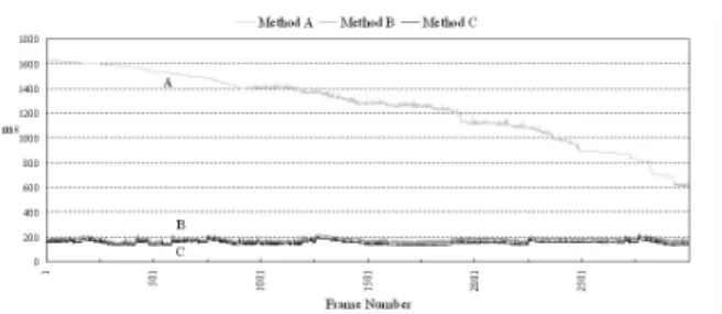
l Method A: (Geometry) The scene is rendered by the traditional graphics using view frustum culling and progressive meshes.
l Method B: (Depth Mesh) The proposed hybrid scheme.
l Method C: (Image Caching) Similar to method B, except that cached images without depth are used. Our test scene is a statuary park which is formed by 104 objects with 484,831 polygons; see Figure 2. The test platform is a Pentium II 350Mhz with 256MB main memory and an nVidia TNT with 16MB graphics accelerator. We compare the performance in term of frame time and polygon number for each frame, and compare the quality by subjective fidelity criteria (human eyes) and objective fidelity criteria root-mean-square error erms and signal-to-noise ratio
SNR(dB). The ermsand SNR are defined as follows.
where is the pixel color of the approximated image at position (x, y), M and Nare the dimensions of the image.
5.1 Per for mance
Table 1 depicts the average frame time and the average polygon number of 3000 frames each for the path 1 and the path 2. In polygon-count comparison, the method
B has in average only 15% of the polygons required by A, and slightly more polygons than C.
For a scene in which all geometries are uniformly distributed, the polygon number inside each image cell will be almost constant. Moreover, the rendering costs of a depth mesh and a cached image are mostly
dependent on the image resolution. Therefore, the rendering time of B and C are almost the same, more constant, and much less than that of A (see Figure 3.) Note that, the polygon number of A is decreasing with the frame number due to the fact that more and more polygons are clipped out by the visibility culling in both path 1 and path 2.
5.2 Quality
Figure 4 shows the images rendered by method A, B, and C respectively. We see that the positions of geometries are correct in B, but there are a few differences in shapes and lighting effects. This is due to the fact that depth mesh triangulation algorithm could not properly capture small detail features. The method
C is even worse, the position of the building on the left
of Figure 4(c) is not correct. This will result in sudden jump during cell transition. In our experiment, we often perceive such sudden jumps in C.
Table 2 shows the average quality loss of B and C compare to the pure geometric rendering using original geometry without LOD. Note that, human eye in general
would not able to distinguish between two images that have a signal-to-noise ratio (SNR) greater than 25dB. Figure 5 shows the SNR for each frame of the path 1. We can see that the SNR of B between 14 and 18 and is much stable than C. This is mainly due to the fact that parallax errors have been removed by re-projecting the depth meshes. As a result, it will have a great quality improvement with only a little performance loss in re-projecting the depth meshes. Table 3 depicts the average ermsand SNR between frames before and after
cell transition. Method B has high average SNR 20.8
and 22 for path 1 and path 2, respectively.
5.3 Cell Size and Cell Ratio Consider ations
We use JPEG algorithm to compress our cached images to reduce the storage requirements and reduce the loading time as well. Decompression needed at run-time can be supported by the state-of-the-art graphics hardware with texture decompression (e.g., S3’s S3TC.)
Since the storage requirement of a depth mesh and a cached image are both dependent on the image resolution (dimension) and an almost constant amount of depth meshes and cached images would be required to navigate a scene, the memory requirement for B and C will be almost constant; as shown in Table 4. On the other hand, as we mentioned in the Section 3.1.1, we could make a tradeoff between the quality and performance. The smaller navigation cell size, the smaller amount of local geometries is. Thus, it should have a better performance for a smaller navigation cell size. However, with a smaller cell size, there will be more navigation cells and, in turns, frequent transitions and more frequent data loading are required.
6 DISCUSSION & FUTURE WORK
In this project, we propose a hexagonal spatial subdivision and a hybrid scheme for navigating complex scenes. The method can achieve a smooth, with no apparent popping effects, navigation at an almost constant and interactive frame rate. By cooperating with the re-projection of depth meshes, parallax error and popping effect will be minimized. Furthermore, we could easily make a tradeoff between performance and quality requirement by specifying the pixel-error tolerance for cell-size ratio. As the future works, a better adaptive triangulation algorithm for the depth image which is able to capture the detail features with low increase in polygon count will be also of interest. Current implementation considers only the constant cell ratio. To utilize the spatial properties, a floating cell ratio approach could be considered.
Refer ences
[1] M. Bern and D. Eppstein. Mesh Generation and Optimal Triangulation. In F. K. Jwang and D.-Z. Du, editors, Computing in Euclidean Geometry, pages 23–90, Singapore, 1992. World Scientific. [2] S. E. Chen and L. Williams. View Interpolation for
Image Synthesis. In J. T. Kajiya, editor, Computer Graphics (SIGGRAPH 93 Proceedings), pages 279–288, August 1993.
[3] L. Darsa, B. Costa, and A. Varshney. Walkthroughs of Complex Environments using Image-based Simplification. In Computers & Graphics, volume 22, pages 55–69, 1998. [4] N. Greene, M. Kass, and G. Miller. Hierarchical
ZBuffer Visibility. In J. T. Kajiya, editor,
Computer Graphics (SIGGRAPH 93 Proceedings), pages 231–238, August 1993. [5] H. Hoppe. Progressive Meshes. In H. Rushmeier,
editor, Proceedings of SIGGRAPH 96, pages 99–108. ACM SIGGRAPH, Addison Wesley, August 1996.
[6] H. Hoppe, T. DeRose, T. Duchamp, J. McDonald, and W. Stuetzle. Mesh Optimization. In J. T. Kajiya, editor, Computer Graphics (SIGGRAPH 93 Proceedings), pages 19–26, August 1993.
[7] T. Hudson, D. Manocha, J. Cohen, M. Lin, K. Hoff, and H. Zhang. Accelerated Occlusion Culling using Shadow Frusta. In Proceedings of 13th Symposium on Computational Geometry, pages 1–10, 1997.
[8] L. McMillan and G. Bishop. Plenoptic Modeling: An Image-Based Rendering System. In R. Cook, editor, Proceedings of SIGGRAPH 95, pages 39–46. ACM SIGGRAPH, Addison Wesley, August 1995.
[9] J. Rossignac and P. Borrel. Multi-resolution 3-D Approximations for Rendering Complex Scenes. In B. Falcidieno and T. L. Kunii, editors,
Modeling in Computer Graphics, pages 455–465, Berlin, 1993. Springer-Verlag.
[10] G. Schaufler and W. St¨urzlinger. A Three-Dimensional Image Cache for Virtual
Reality. In Proceedings of Eurographics ’96, pages 227–236, August 1996.
[11] W. J. Schroeder, J. A. Zarge, and W. E. Lorensen. Decimation of Triangle Meshes. Computer Graphics, 26(2):65–69, 1992.
[12] S. M. Seitz and C. R. Dyer. View Morphing. In H. Rushmeier, editor, Proceedings of SIGGRAPH 96, pages 21–30. ACM SIGGRAPH, Addison Wesley, August 1996.
[13] J. Shade, D. Lischinski, D. H. Salesin, T. DeRose, and J. Snyder. Hierarchical Image Caching for Accelerated Walkthroughs of Complex Environments. In H. Rushmeier, editor,
Proceedings of SIGGRAPH 96, pages 75–82. ACM SIGGRAPH, Addison Wesley, August 1996.
[14] J. W. Shade, S. J. Gortler, L.-W. He, and R. Szeliski. Layered Depth Images. In Proceedings of SIGGRAPH 98, pages 231–242. ACM SIGGRAPH, Addison Wesley, July 1998.
[15] F. Sillion, G. Drettakis, and B. Bodelet. Efficient Impostor Manipulation for Real-Time Visualization of Urban Scenery. In Proceedings of Eurographics’97, pages 207–218, Budapest, Hungary, September 1997.
[16] S. K. Yang. Material-Preserving Progressive Mesh Using Geometry and Topology Simplification. Master’s thesis, Department of Computer Science and Information Engineering, National Chiao Tung University, 1999.
[17] H. Zhang, D. Manocha, T. Hudson, and K. Hoff. Visibility Culling Using Hierarchical Occlusion Maps. InComputer Graphics, volume 31, pages 77–88, 1997.