Chapter 6
A Cellular Quorum Scheme for Location Management
_____________________________________
6.1. System Description
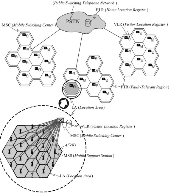
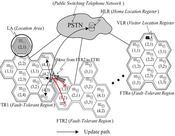
The framework of the system network is shown in Fig. 6-1. The system is
modeled as a geographical area that consists of many cells. The cells are aggregated
into contiguous geographical areas called location areas (LAs), which are
symbolized by the big hexagons shown in Fig. 6-1. The mobile node, referred to as
the mobile host (MH), is a part of only one cell at a time. A fixed base station, called
the mobile support station (MSS), supports each cell. The communication between
MH and MSS is through radio waves or infrared waves which are wireless. The
mobile support station is static and connected through a dedicated wire-line link to a
mobile switch center (MSC). An MSC, which typically provides switching and can
be viewed as a bridge for connecting the wireless network and the wired network,
serves one LA. A visitor location register (VLR) is maintained at each LA, which
stores the temporary records of the current location information of the MH while it is
not at “home”. Several LAs are grouped into a fault-tolerant region (FTR). All the
VLRs in one FTR are formed as a local fault-tolerant system, which can tolerate the
failures of one or more VLRs. The mechanism of the fault-tolerance will be described in section 6.3. All MSCs are finally connected to a Public Switched Telephone Network (PSTN) that is a wired backbone network. The system is a two-tier database architecture consisting of a home location register (HLR) and
PSTN
HLRHLR (Home Location Register )
VLR
VLR
LA (Location Area)
MSS (Mobile Support Station ) (Cell)
MSC (Mobile Switching Center ) VLR (Visitor Location Register ) (Public Switching Telephone Network )
FTR (Fault-Tolerant Region)
LA (Location Area)
VLR (Visitor Location Register ) MSC (Mobile Switching Center )
Fig. 6-1. System architecture with cellular quorum system
visitor location registers (VLRs). The HLR cooperates with VLRs to track and find the locations of MHs. The information, recorded in the HLR database, can assist the system in finding the FTR where the MH is currently located. Then, the LA where the MH resides is tracked. In the next section, we will describe the cellular quorum approach that will be used in our system design.
6.2. Cellular Quorum Constructions
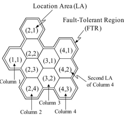
In the following, we introduce a cellular quorum approach which is based on the hexagonal location areas (LAs). Consider a fault-tolerant region (FTR) with continuous location areas (LAs) shown in Fig. 6-2. Each LA can be identified with position coordinates (x,y). We denote the LA(x,y) as the position of LA that is located at the position coordinates (x,y), where x denotes the column number of the FTR and y denotes the sequential order where it appears in its column. Some sequences of patterns in the FTR are employed as Update-quorum (U-quorum) and Query-quorum (Q-quorum).
(1,1) (2,1)
(2,2) (2,3)
(2,4) (3,1)
(3,2) (4,1)
(4,2)
(4,3) Location Area (LA)
Fault-Tolerant Region (FTR)
Column 1
Column 2 Column 4 Column 3
Second LA of Column 4
Fig. 6-2. A fault-tolerant region (FTR) and its position coordinate.
DEFINITION 6: Let N be the total number of columns in a FTR region and M
ibe the total number of rows in the column i of the FTR region. In the cellular quorum construction of one FTR region, the Update-set (U-set) and Query-set (Q-set) are defined as follow:
U-set = {U
i| 1 ≤ i≤ N, U
i={(i,j) | 1 ≤ j≤ M
i};
Q-set = {Q
s| 1 ≤ s, Q
s={(i, r
is) | 1 ≤ i≤ N },
where r
is(1 ≤ r ≤
isM
i) is the row number randomly selected with variable s in
column i; i, j, s, N, M
iand r
isare all natural numbers. Each element of U-set and Q-set is called an U-quorum and a Q-quorum, respectively.
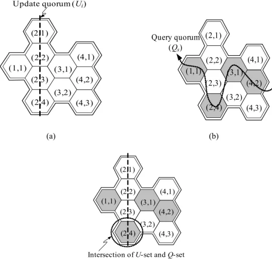
For example, consider a fault-tolerant region (FTR) with continuous location areas (LAs), which are identified with position coordinates (x,y) shown in Fig. 6-3.
Then, we have U-set = {U
1,U
2,U
3,U
4}= {{(1,1)},{(2,1),(2,2),(2,3),(2,4)},{(3,1),
(3,2)},{(4,1),(4,2),(4,3)}}, where U
i, for example, {(2,1),(2,2), (2,3),(2,4)}, is an
update quorum (U-quorum) shown in Fig. 6-3(a); moreover, according to the random
selection (i.e., randomly pick one LA from each column), we may have the Q-set =
{Q
1,Q
2,…,Q
n,…} ={{(1,1),(2,4),(3,1),(4,2)},{(1,1),(2,1),(3,2),(4,2)},…,{(1,1),(2,4),
(3,3),(4,1)},…}, where Q
i, for example, {(1,1),(2,4),(3,1),(4,2)}, is an query quorum
(Q-quorum) shown in Fig. 6-3(b).
(1,1) (2,1)
(2,2)
(2,3)
(2,4) (3,1)
(3,2) (4,1)
(4,2)
(4,3) Update quorum (Ui)
(1,1) (2,1)
(2,2) (2,3)
(2,4) (3,1)
(3,2) (4,1) (4,2)
(4,3) Query quorum
(Qs)
(a) (b)
(1,1) (2,1)
(2,2) (2,3)
(2,4) (3,1)
(3,2) (4,1) (4,2)
(4,3) Intersection of U-set and Q-set
(c)
Fig. 6-3. The construction and intersectional property of U-quorum and Q-quorum.
Theorem 4: The U-set and Q-set defined in Definition 6 satisfy the properties of
Legion structure {C
i, C
j}.
Proof: According to Definition 3, the properties of Legion structure {U-set, Q-set}
are: (I) U-set and Q-set are set systems. (II) Any pair of U-quorum in U-set and
Q-quorum in Q-set have joint elements. We need to prove these properties. First,
according to Definition 3 and Definition 1, it is easy to see that U-set and Q-set are
set systems. Second, according to Definition 6, the U-quorum’s elements are picked
from the same column’s LAs of FTR and one LA from each column of FTR is randomly picked as the Q-quorum’s element. Hence, the U-quorum’s elements are all in the same column and one of them must be chosen as one member in the Q-quorum. Thus, there is one intersectional element of each pair of U-quorum and Q-quorum. This satisfies property (II). Hence, the U-set and Q-set of cellular quorum system satisfy the properties of Legion structure. □
Consider the previously described example. The U-quorum, for example, U
2={(2,1),(2,2),(2,3),(2,4)}, is composed from all the LAs of column 2 of FTR (Fig.
6-3(a)). The Q-quorum, for example, Q
1={(1,1),(2,4),(3,1),(4,2)}, is composed from the LAs that are picked from each column (Fig. 6-3(b)). Thus, there is one intersectional element (2,4) of the U-quorum and Q-quorum (Fig. 6-3(c)).
6.3. The System Design
In this section, we use the cellular quorum approach described in section 6.2 to devise a fault-tolerant location tracking system. Based on the intersectional property of the U-quorum and Q-quorum, the location information is disseminated to VLRs of the U-quorum and can be extracted from one of them by using the Q-quorum even though one or more location servers fail. In cellular PCS systems, location management is achieved by querying and updating. A query occurs when a host needs to communicate with another mobile host whose location is unexpected, and an update occurs when a mobile host changes its location. A detailed description of update and query procedures will be discussed in the sections 6.3.1 to 6.3.4.
In a traditional location management scheme, an update procedure that would
need to coordinate between HLR and VLRs will occur whenever an MH moves to a new LA. In our approach, when an MH moves to a new LA in the same FTR, instead of updating information to the HLR, it merely reports its location to the VLRs of U-quorum in the local FTR. We divide the update procedure into two types: region update and home update. When an MH roams to another FTR, a home update procedure will be triggered. By the user mobility behavior model, we could suitably choose the coverage areas of one FTR. Then, with high probability, the users would move around in the same FTR. Hence, in most conditions, the update procedures will be handled locally.
6.3.1. Region Update
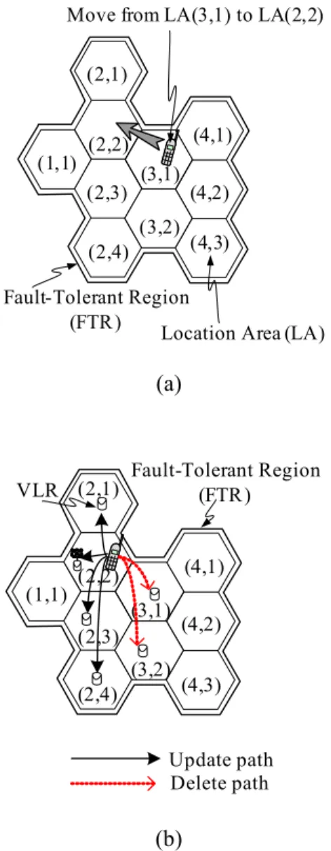
In the following, we use the cellular quorum approach, defined in Definition 6, to implement the region update algorithms. When a mobile host moves from one LA to others in the same FTR, its location information has to be updated locally (Fig. 6-4).
Therefore, the following steps are performed as the region update procedure:
The UPDATE message is sent to the current MSC which forwards this message to all the VLRs in the U
iquorum of the FTR, where i is the column that the MH resides currently.
Upon receiving the UPDATE message, the VLRs add the new location information received to their databases and send back the ACK message.
If the procedure does not receive all the ACK messages from all VLRs in the
quorum during a given period of time, then it randomly selects another U
j, where
1 ≤ j≤ N, sends the UPDATE message to all VLRs in the new quorum again, and
goes to step 2; otherwise, it goes to next step.
The DELETE message is sent to the current MSC which forwards this message to all the VLRs in the U
kquorum of the FTR, where k is the column in which the MH resided previously.
Upon receiving the DELETE message, the VLRs delete the old location information in their databases and send back the ACK message.
If the procedure does not receive all the ACK messages from all VLRs in the quorum during a given period of time, then it resends the DELETE message to VLRs that did not send back ACK messages, and goes to step 5; otherwise, it stops.
Consider a fault-tolerant region (FTR) with continuous location areas (LAs), which can be identified with position coordinates (x,y) shown in Fig. 6-4. According to the Definition 6, the U-set is {U
1,U
2,U
3,U
4}={{(1,1)},{(2,1),(2,2),(2,3),(2,4)}, {(3,1),(3,2)},{4,1},{(4,2),(4,3)}}. If a mobile host h moves from LA(3,1) to LA(2,2), new location information is sent to the all the VLRs of LA(2,1), LA(2,2), LA(2,3), and LA(2,4) in the U
2quorum of the FTR and the ACK messages are sent back.
Then, the DELETE message is sent to all the VLRs of LA(3,1) and LA(3,2) in the
U
3quorum of the FTR, where the column three is the column in which the MH
resided previously, and the ACK messages are sent back.
(1,1) (2,1)
(2,2) (2,3) (2,4)
(3,1) (3,2)
(4,1)
(4,2) (4,3)
Location Area (LA) Move from LA(3,1) to LA(2,2)
Fault-Tolerant Region (FTR)
(a)
(1,1) (2,1)
(2,2)
(2,3) (2,4)
(3,1) (3,2)
(4,1) (4,2)
(4,3)
Fault-Tolerant Region (FTR)
Update path Delete path VLR
(b)
Fig. 6-4. Region Update. (When a MH moves form one LA to another LA in the same FTR.)
In the IS-41 location management scheme, if the distance between the visited
area and the HLR is large, the signaling delay for the location update is long. Our
approach, a region update, is a way to reduce the signaling delay for performing
updates. This is especially useful when the MH always moves within a particular
FTR.
6.3.2. Home Update
When roaming around the whole network, an MH may go through different FTRs. If an MH enters another FTR, a home update procedure will be triggered (Fig.
6-5). The procedure is described as follows:
The procedure sends the UPDATE message to the current MSC which forwards this message to all the VLRs in the U
iquorum of the FTR, where i is the column in which the MH resides currently, and concurrently sends the REDIRECT pointer (i.e., a forwarding route information including the FTR identifier) to the HLR.
Upon receiving the UPDATE message or REDIRECT pointer, the VLRs or HLR add the new information received to their databases and send back the ACK message.
If the procedure does not receive all the ACK messages from all VLRs in the quorum or the ACK message form the HLR during a given period of time, then it randomly selects other quorum U
j, where 1 ≤ j≤ N, sends the UPDATE message to all VLRs in the new quorum again or resends the REDIRECT pointer to the HLR, and goes to step 2; otherwise, it goes to the next step.
The DELETE message is sent to the current MSC which forwards this message to all the VLRs in the U
kquorum of the FTR, where k is the column in which the MH resided previously.
Upon receiving the DELETE message, the VLRs delete the old location information in their databases and send back the ACK message.
If the procedure does not receive all the ACK messages from all VLRs in the
quorum during a given period of time, then it resends the DELETE message to VLRs that did not send back ACK messages, and goes to step 5; otherwise, it stops.
PSTN
HLRHLR (Home Location Register) (Public Switching Telephone Network )
FTR1 (Fault-Tolerant Region )
LA (Location Area) VLR (Visitor Location Register )
Update path Delete path FTR2 (Fault-Tolerant Region )
FTRn (Fault-Tolerant Region) (1,1)
(2,1)
(3,1) (4,1)
(1,1) (2,1)
(3,1)
(4,1)
(1,1) (2,1)
(3,1) (2,2)
(2,3)
(2,4) (3,2)
(4,2)
(4,3)
(1,2)
(3,2)
(3,3) (4,2)
(1,2)
(1,3) (2,2)
(2,3) (3,2)
(3,3) Move from FTR2 to FTR1
Fig. 6-5. Home update. (When a MH moves form one LA to another LA in different FTR.).
Consider n fault-tolerant regions (FTRs) each with continuous location areas (LAs), which can be identified with position coordinates (x,y) shown in Fig. 6-5.
According to the Definition 6, the U-set of FTR1 is {
U U11, 12,U U13, 41}={{(1,1)},{(2,1),(2,2), (2,3),(2,4)},{(3,1),(3,2)},{4,1},(4,2),(4,3)}}
and the U-set of FTR2 is {
U2,U2,U2,U2} ={{(1,1),(1,2)},
{(2,1)},{(3,1),(3,2),(3,3)},{4,1}, (4,2)}}. If a mobile host h moves from LA(1,1) of FTR2 to LA(4,2) of FTR1, new location information is sent to the all the VLRs of LA(4,1), LA(4,2), and LA(4,3) in the
U14quorum of the FTR1 and the ACK messages are sent back by VLRs. Meanwhile, the REDIRECT pointer (i.e., a forwarding route information including the FTR identifier that indicates the FTR in which the MH currently resides.) is sent to the HLR and the ACK message is sent back by the HLR. Then, the DELETE message is sent to all the VLRs of LA(1,1) and LA(1,2) in the
U12quorum of the FTR2 and the ACK messages are sent back by VLRs.
As described in the above procedure, the VLRs in the selected quorum of the current FTR maintain the id of the current MSC serving the MH. For the HLR, it maintains the id of the FTR where the MH currently resides.
When a mobile host wishes to communicate with another host whose location is unknown, the query procedure is invoked. Again, the fault-tolerant cellular quorum approach is used in the location query process. We have designed the query procedure as two types: region query and home query, and describe them in Section 6.3.3 and 6.3.4, respectively.
6.3.3. Region Query
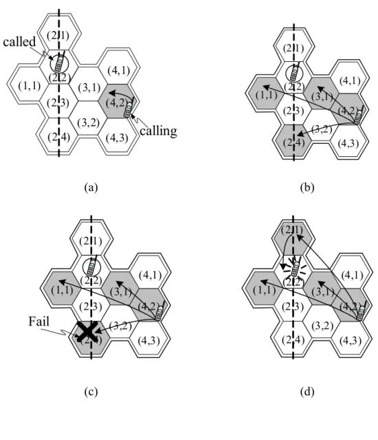
A region query occurs when the calling and called MH are in the same FTR. Fig.
6-6 shows the region query processes. The procedure is described in the following
steps:
• The calling MH queries the location information of the called MH form its local VLR (Fig. 6-6(a)). If the information is found in the local VLR, then the local VLR forwards the routing request (ROUTREQ) message to the called MH’s current MSC/VLR (Note that the called MH and the calling MH may be located in the same LA.) and sends the ACK message back to the procedure. Finally, the current MSC/VLR launches a paging process to find the called MH’s current
(1,1) (2,1)
(2,2) (2,3)
(2,4) (3,1)
(3,2) (4,1)
(4,2)
(4,3)
calling called
(a)
(1,1) (2,1)
(2,2) (2,3)
(2,4) (3,1)
(3,2) (4,1)
(4,2)
(4,3)
(b)
(1,1) (2,1)
(2,2) (2,3)
(2,4) (3,1)
(3,2) (4,1) (4,2)
(4,3)
Fail
(c)
(1,1) (2,1)
(2,2) (2,3)
(2,4) (3,1)
(3,2) (4,1) (4,2)
(4,3)
(d)
Fig. 6-6. Region query
.
MSS. At this point the call is established and then the query procedure is stopped.
Otherwise, it goes to next step.
• The procedure randomly selects a quorum Q
sand sends a QUERY message to all the VLRs (except the VLR which locates at the same column with the calling MH’s local VLR) in the quorum (Fig. 6-6(b)).
• Upon receiving the QUERY message, the VLR, which does not have a copy of queried information, sends the null ACK message back to the procedure. On the other hand, if the information is found in the VLR, then it forwards the routing request (ROUTREQ) message to the called MH’s current MSC/VLR and sends the ACK message back to the procedure. Then, the current MSC/VLR launches a paging process to find the called MH’s current MSS. At this point the call is established and then the query procedure is stopped. Otherwise, it goes to next step.
• If the call is not established after a given period of time, then the procedure resends the QUERY message to the randomly selected VLRs, which located at the same column with the VLRs that did not send back the ACK messages and goes to step 3 (Fig. 6-6(d)). Otherwise, it stops.
Consider a fault-tolerant region (FTR) with position coordinates (x,y) shown in Fig. 6-6. According to the Definition 6, we may have the Q-set={Q
1,Q
2,…,Q
n,…}=
{{(1,1),(2,4),(3,1),(4,2)},{(1,1),(2,1),(3,2),(4,2)},…,{(1,1),(2,4),(3,3),(4,1)},…}.
Assume a called host h stored its information at the VLRs of LA(2,1), LA(2,2),
LA(2,3), and LA(2,4) in the U
2quorum of the FTR. When a calling host h’ at
LA(4,2) of the same FTR wants to communicate with host h, it first acquires the
information from the local VLR of LA(4,2). Since the information is not found in the local VLR, then the procedure randomly select a quorum, for example, Q
1, and sends a QUERY message to all the VLRs of LA(1,1), LA(2,4), and LA(3,1) in the quorum Q
1(except the local VLR of LA(4,2)). But, the only VLR that keeps the information of h in quorum Q
1has failed. So, the procedure resends the QUERY message to the randomly selected VLR of LA(2,1), which located at the same column with the VLR of LA(2,4). The VLR of LA(2,1), which has the location information of called MH, forwards the routing request (ROUTREQ) message to the called MH’s current MSC/VLR. Then the query procedure is completed.
The completion of the region FTR query procedure is quick, since it is done locally. Compared to the query in the IS-41 scheme, which accesses the HLR that may be far away from the calling MH, our region FTR query is more time effective since the access to HLR could involve two long-distance legs.
6.3.4. Home Query
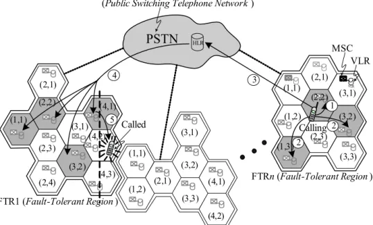
If the calling and called host are in different FTRs, the communication invokes the home query procedure. Fig. 6-7 shows the home query processes. The procedure is described as follows:
First, the region query procedure (as described in the Section 6.3.3) is processed in the local FTR in which the calling MH resides. Since the calling and called MH are in different FTRs, the null ACK messages, which issued by all VLRs in the quorum, would be received by the procedure.
Then, the HLR is inquired for the location information of the called MH.
PSTN
HLRVLR
(Public Switching Telephone Network )
FTR1 (Fault-Tolerant Region )
Calling
VLR MSC
Query path FTR2 (Fault-Tolerant Region )
FTRn (Fault-Tolerant Region ) Called
1 2 3
2 4
5 (1,1)
(2,1) (2,2)
(2,3)
(2,4) (3,1)
(3,2) (4,1)
(4,2)
(4,3) (1,1)
(1,2) (2,1) (3,1)
(3,2)
(3,3) (4,1)
(4,2)
(1,1)
(1,2)
(1,3) (2,1) (2,2)
(2,3) (3,1) (3,2)
(3,3)
Fig. 6-7. Home query.
According to the REDIRECT pointer in the database, the HLR forwards the QUERY message to the VLRs in the randomly selected quorum, Q
j, of the FTR in which the called MH resides.
Upon receiving the QUERY message, the VLR, which has not a copy of
queried information, sends the null ACK message back to the procedure. On the
other hand, if the information is found in the VLR, then it forwards the routing
request (ROUTREQ) message to the called MH’s current MSC/VLR and sends
the ACK message back to the procedure. Then, the current MSC/VLR launches
a paging process to find the called MH’s current MSS. At this point the call is
established and then the query procedure is stopped. Otherwise, it goes to next
step.
If the call is not established after a given period of time, then the procedure resends the QUERY message to the VLRs, which are located at the same column with the VLRs that did not send back the ACK messages and goes to step 4. Otherwise, it stops.
Consider n fault-tolerant regions (FTRs) system with position coordinates (x,y)
shown in Fig. 6-7. According to the Definition 6, the Q-set of FTR1 may be
{
Q Q Q11, 21, 13, ...}={{(1,1),(2,4),(3,1),(4,2)},{(1,1),(2,1),(3,2),(4,2)},{(1,1),(2,2),
(3,2),(4,1)},…} and the Q-set of FTRn may be {
Q1n,Q2n,Q3n, ...} ={{(1,3),(2,2)},
{(3,2)},{(1,1),(2,1),(3,2)},{(1,3),(2,3),(3,3)},…}. Assume a called host h stored its
information at the VLRs of LA(4,1), LA(4,2), and LA(4,3) in the quorum
U14of the
FTR1. When a calling host h’ at LA(2,2) of FTRn wants to communicate with host h,
it first acquires the information from the local VLR of LA(2,2). Since the
information is not found in the local VLR, then the procedure randomly select a
quorum, for example,
Q1n, and sends a QUERY message to all VLRs of LA(1,3), and
LA(3,2) in the quorum
Q1n(except the local VLR of LA(2,2)). Since the called MH
is not located at FTRn, all VLRs in
Q1nhave not the location information of called
MH and send null ACKs back. Then, the HLR is inquired for the location
information of the called MH. According to the REDIRECT pointer in the database,
the HLR forwards the QUERY message to the VLRs of LA(1,1), LA(2,2), LA(3,2),
and LA(4,1) in the randomly selected query quorum
Q31of the FTR1 in which the
called MH resides. Since (4,1) is the intersectional element of
U41and
Q31, the VLR
of LA(4,1) has the location information of called MH and forwards the routing
request (ROUTREQ) message to the called MH’s current MSC/VLR. Then the home query procedure is completed.
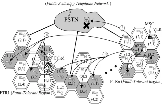
6.3.5. Dealing with the Failure of the HLR
In some accident situations, the HLR may be down for a period of time. In this section, we will discuss the approach to deal with the situation when the HLR fails.
If the HLR is down, then the home query can not be performed. When a mobile host wishes to communicate with another host whose location is not in the same FTR, the connection can not be achieved. In this situation, the procedure is switched to
PSTN
HLRVLR
(Public Switching Telephone Network )
FTR1 (Fault-Tolerant Region )
Calling
VLR MSC
Query path ( Multicast ) FTR2 (Fault-Tolerant Region )
FTRn (Fault-Tolerant Region ) Called
1 2 4
2
5 4
(1,1) (2,1) (2,2)
(2,3)
(2,4) (3,1)
(3,2) (4,1)
(4,2)
(4,3) (1,1)
(1,2) (2,1) (3,1)
(3,2)
(3,3) (4,1)
(4,2)
(1,1)
(1,2)
(1,3)
(2,1) (2,2)
(2,3) (3,1) (3,2)
(3,3) 3
Fig. 6-8. Dealing with the failure of the HLR.
multicast the QUERY message to all the VLRs in the randomly selected Q-quorum of each FTR (Fig. 6-8). Upon receiving the QUERY message, the VLR, which has not a copy of queried information, sends the null ACK message back to the procedure. On the other hand, if the information is found in the VLR, then it forwards the routing request (ROUTREQ) message to the called MH’s current MSC/VLR and sends the ACK message back to the procedure. Then, the current MSC/VLR launches a paging process to find the called MH’s current MSS. At this point the call is established and then the query procedure is stopped.
6.4. Connection Establishment Delay Analysis
Since our scheme retrieves the MH location information in the location servers of a quorum set of the local region as much as possible to avoid long delay caused by the possible long-distance of VLR and HLR, we will analyze the effect on the connection establishment delay by comparing the query latency between proposed scheme and the IS-41 scheme. The query latency is divided into two parts: region query latency and home query latency. We introduce parameters for analyses in the following:
L
l: latency for transmitting a message through the local link (within the FTR).
L
r: latency for transmitting a message through the remote link (out of the FTR).
L
VLR: latency for a query to the VLR.
L
HLR: latency for a query to the HLR.
We first calculate the query latency for our proposed scheme, which is associated
with the hit ratio. The h is assumed to be a region hit ratio. Let L
Regionand L
Homebe
the query latencies of the protocols when there is a hit query (which means the
location information is found in the FTR where the calling MH currently resides) and a miss query, respectively.
In addition to latencies for sending messages through the local link, there are database access latencies of VLRs. In hit case, we have a query latency equation
(60)
where L
pagingis the latency to page a user in a LA.
In the case of a miss, the HLR and LAs of the remote FTR are inquired.
Therefore, additional latencies for sending messages through the remote links, the latencies for querying the redirect pointer of the HLR, and latencies for access to the VLRs are needed. Thus, we have a query latency equation of a miss case
(61)
The average query latency L
Queryis then given by
(62)
In the IS-41 approach, a query message is transmitted to the HLR to acquire the called MH’s location information; and the routing-request message is issued from HLR to the called VLR. Then, the location information is sent to the calling MSC.
Therefore, the average query latency for IS-41 scheme is
(63)
6 2 ,
Region l VLR paging
L = L + L + L
6 4 3 .
Home l r VLR HLR paging
L = L + L + L + L + L
(1 ) .
Query Region Home
L = hL + − h L
41
4 2 .
IS
Query r VLR HLR paging
L
−= L + L + L + L
In [41], the relation between the hit ratio and call to mobility ratio (CMR) was calculated as
(64)
where the CMR was expressed as the ratio of the call arrival rate to the mobility rate.
6.5. Numerical Results and Discussion
The evaluations and comparisons of the query delay for the proposed scheme and the conventional IS-41 scheme are presented in this section. We normalize the value of L
lto one for evaluating the latency. The values of the latency ratios of L
l: L
r= 1:5 and L
l: L
paging= 1:0.2 are used. Further, we assume the latency ratio of L
VLR: L
HLR= 1:5.
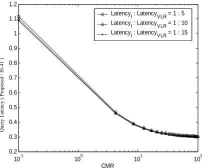
Fig. 6-9. Comparisons of query latency under various CMR.
Query Latency ( Proposed / IS-41 )
10-1 100 101 102
0.2 0.3 0.4 0.5 0.6 0.7 0.8 0.9 1 1.1 1.2
CMR Latency
l : Latency
VLR = 1 : 5 Latency
l : Latency
VLR = 1 : 10 Latency
l : Latency
VLR = 1 : 15
/(1 ),
CMR h = − h
Fig. 6-9 shows the relation between call to mobility ratio (CMR) and the query latency for proposed and IS-41 schemes. Three data sets are considered when L
l: L
VLR= 1:5, 1:10, and 1:15. This figure indicates that by using our proposed scheme the query latency is reduced, if the CMR ratio is more than 0.125. Since the region (hit case) queries are quickly processed locally without inquiring the database of the HLR, the average query latency can be decreased. This figure illustrates the more CMR ratio we have, the less query latency we get. For example, when CMR = 1, the query latency of the proposed scheme is about 30% less than that of the IS-41 scheme.
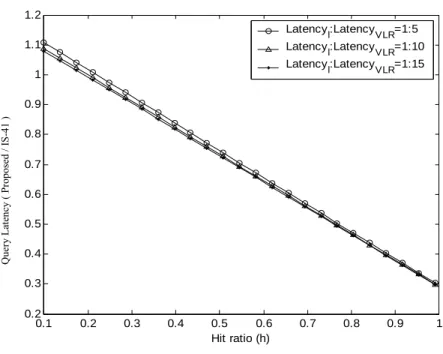
Fig. 6-10 represents the query latency for the varying hit ratio (h) between the proposed and the IS-41 scheme. The figure shows the linear relation between the
Fig. 6-10. Comparisons of query latency under various hit ratio.
0.1 0.2 0.3 0.4 0.5 0.6 0.7 0.8 0.9 1
0.2 0.3 0.4 0.5 0.6 0.7 0.8 0.9 1 1.1 1.2
Hit ratio (h)
Latencyl:LatencyVLR=1:5 Latencyl:LatencyVLR=1:10 Latencyl:LatencyVLR=1:15
Query Latency ( Proposed / IS-41 )