行政院國家科學委員會專題研究計畫 成果報告
水體底泥介面污染質質量傳輸之理論與數值分析(III)
計畫類別: 個別型計畫
計畫編號: NSC92-2211-E-006-031-
執行期間: 92 年 08 月 01 日至 93 年 07 月 31 日
執行單位: 國立成功大學水利及海洋工程學系(所)
計畫主持人: 賴泉基
計畫參與人員: 詹勳全
報告類型: 精簡報告
處理方式: 本計畫可公開查詢
中 華 民 國 93 年 10 月 28 日
行政院國家科學委員會專題研究計畫成果報告
水體底泥介面污染質質量傳輸之理論與數值分析(Ⅲ)
Study on the Pollutants Mass Transfer at Sediment-Water
Interface (Ⅲ)
計畫編號:NSC 92-2211-E-006-031
執行期限:92 年 08 月 1 日至 93 年 07 月 31 日
主持人:賴泉基 國立成功大學水利及海洋工程研究所
共同主持人:呂珍謀 國立成功大學水利及海洋工程研究所
計畫參與人員:詹勳全 國立成功大學水利及海洋工程研究所
一、中文摘要
本研究探討完全發展的紊流通過透水底床的 特性,透水底床內的流體以體積平均的那維爾史托 克方程式(Navier-Stokes equation)加以模擬,由於流 體於純水區域與透水區域交界面屬於連續狀態,乃 利用單一區域解法混合介質之流體運動。藉由改變 孔隙率φ (0.6∼0.8)與達西數 Da (1.6×10⁻³~1.6×10⁻⁵) 評估透水底床對純水區域與透水區域內流體特性 的影響,純水區域流速計算結果顯示,紊流滲入透 水區域與交界面附近的動量交換,造成此區域流速 的減低。由於紊流剪應力的傳播穿過交界面,壁函 數(wall function)不再適用於紊流通過具透水性之 底床,紊流剪應力滲入透水底床的深度與透水底床 本身的特性呈現高度的相關性。與紊流通過不透水 底床比較,紊流穿過純水區域與透水區域交界面且 滲入透水區域內的現象,對高滲透性之多孔介質而 言相對重要。 關鍵詞:紊流、多孔介質、滲透係數、底床Abstract
This study investigates the characteristics of fully developed turbulent flow in an open channel with a permeable bed. The flow within the permeable bed is modeled by using the Volume-Averaged Navier-Stokes equations. The single-domain approach is applied as a numerical implementation for solving such a hybrid domain. The effect of the permeable bed on the flow properties over and inside is archived with a varying porosity from 0.6 to 0.8 and a varying Darcy number Da from 1.6×10⁻³ to 1.6×10⁻⁵. The
computed velocities in the clear fluid show a significant decrease with increasing porosity and Darcy number due to the penetration of turbulence into the porous medium and momentum transfer near the fluid/porous interface region. The turbulent shear propagates across the interface is valid for wall function being inappropriate to describe flow over the permeable bed. The thickness of turbulent shear stress penetrated into porous medium is strongly related to the damping effect caused by the porous medium
itself. In the contrast with the impermeable wall, the penetration of turbulent flow across the interface is significant for highly permeable materials.
Keywords: Turbulent flow; Porous media; Open channel flow; Channel beds
二、前言
水流通過多孔介質交界面的問題乃環境流體 力學中相當重要之問題,原因在於其控制著流體與 多孔介質間溶解性有機顆粒、無機離子與氣體之交 換,解析此等問題可視為由純水區域與可透水區域 所共同組成之混合介質之流體運動,流體同時存在 純水區域與可透水區域,可透水區域內部流體之特 性受純水區域之影響,求解時兩者需加以連結。一 般而言,純水區域之流體滿足那維爾史托克方程式 (Navier-Stokes equation),而可透水區域內流體流動 則是以達西定律(Darcy’s law)來描述,由於達西定 律在純水區域與可透水區域的交界面上受剪力傳 遞 之 影 響 , 不 滑 動 邊 界 條 件(no-slip boundary condition)不再適用。Beavers & Joseph (1967) 認為 在交界面上流體之速度可以是不連續的,乃提出一 經驗關係式,於交界面上引入一切線滑動速度條件 (slip velocity condition),解決達西定律描述可透水 區 域 內 流 體 速 度 之 邊 界 問 題 ,Neale and Nader (1974)、Vafai and Thiyagaraja (1987)與 Vafai and Kim (1989)質疑滑動速度之正確性,提出流體之速 度與剪力在交界面處需要是連續之觀念,並採用半 經 驗 推 導 之 布 雷 克 曼- 福 海 門 - 達 西 方 程 式 (Brinkman–Forchheimer-extended Darcy equation) 模擬可透水區域內流體運動,前述方程式中代表流 體於孔隙內所受非線性阻力之福海門項,使得動量 方程式可順利應用於交界面上,而且可透水區域內 流體運動可同時滿足可透水區域底部不透水邊界 之不滑動邊界條件,Choi and Waller (1997)在驗證 純水區域與可透水區域的交界面適合邊界條件的 過程中,證實單一區域解法(single-domain approach) 可以處理交界面複雜之傳輸問題。上述以往研究中 多著眼於低雷諾數之層流問題,對於紊流通過透水 區域所引發之物理現象所知依舊有限。紊流是否存在於多孔介質中仍是一個受爭議 之議題,當多孔介質滲透係數很小或孔隙內部流速 很低時,多孔介質內部流體乃處於層流狀態,但在 工程上已經有許多紊流與多孔介質相互作用之應 用實例,當多孔介質為高速度流體所環繞或通過 時,即可能造成多孔介質內部存在紊流之流況, Zippe and Graf (1983)、Venkataraman et al. (1998)與 Prinos et al. (2003)進一步研究指出紊流位於多孔介
質上方或穿過多孔介質時所受之影響,Mendoza
and Zhou (1992) 與 Zhou and Mendoza (1993)求得 紊流通過多孔介質底床時,多孔介質上方流體相關 紊流特性與流速分佈之解析解,但對於多孔介質交 界面處之傳輸現象仍無法得知。 近年來文獻中有多種數學模式描述多孔介質 中流體之紊流現象,根據控制方程式所運用時間平 均運算子(time operator)或體積平均運算子(volume operator)之先後,可將描述多孔介質內流體之紊流 模 式 分 為 :(1) 時 間 - 體 積 平 均 傳 輸 模 式 (time-averaging the volume-averaged transport equations model,Wang and Takle 1995、 Antohe and Lage 1997 與 Getachew et al. 2000);(2) 體積-時間 平均傳輸模式(volume-averaging the time-averaged transport equations model , Travkin and Catton1995、Kuwahara et al. 1998、Nakayama and Kuwahara 1999 、 Masuoka and Takatsu 1996 與 Takatsu and Masuoka 1998);(3)雙平均傳輸模式 (double-decomposition model,Pedras and de Lemos 2000; Pedras and de Lemos 2001a and Pedras and de Lemos 2001b)。上述前兩項模式由於運算子使用先 後的不同,推導出代表不同紊流平均特性之控制方 程式,第三種模式將時間-體積平均與體積-時間平 均理論做連結後,證明運算子使用先後對控制方程 式而言是無關緊要的,使的在計算混合介質內流體 運動時,可以使用單一數學方法加以處理。 本文研究混合介質內流體運動,純水區域之流 況為紊流狀態,為使其交界面處之過渡區域流況做 有效模擬,本研究利用Pedras and de Lemos 所推導 出之巨觀形式(macroscopic form)的控制方程式,模 擬渠道底床為均勻多孔介質之紊流特性,考量阻力 作用與分子黏性的影響,Launder and Sharma (1974) 的低雷諾數k- 紊流模式(low-Reynolds number k-ε turbulence model)乃用來求解純水區域與可透水區 域的控紊流制方程式,計算域與座標系統如圖1 所 示,其中重力方向沿負y 座標方向,假設流體為不 可壓縮流體,厚度為hp之多孔介質位於渠道下半部 陰影部分,具有等向與均勻的特性,其滲透係數為 K,渠道深度為 H(=hf +hp,hf為純水部分之厚度), 雷諾數Re 之定義根據入口 Uin流速與hf,在經由本 研究之討論後,可藉以瞭解紊流通過多孔介質底床 時,純水區域與多孔介質區域內紊流基本特性。
三、數學模式
3.1 平均運算子的定義 自然界的多孔介質由非均勻、不規則與剛性或 彈性的顆粒所組成,一般的數學模式無法有效的解 析其複雜的幾何構造,以往之研究多利用圖2 中代表元素體(representative elementary volume ,REV) 的觀念模擬多孔介質內流體以克服此項限制,根據 體積平均的概念,REV 內的流體特性可以體積平均 運算子表示為 dV V f V f i
∫
∆ ∆ = ϕ ϕ 1 (1) 其中ϕ 為流體特性,∆Vf 為REV 中所含流體的體 積。流體特性ϕ 為 ϕ 與空間變動量 ϕi i 的總和,其 關係式為 ϕ ϕ ϕ= i+ i (2) 由於工程應用上的需要,當高速水流環繞或穿 過多孔介質,而多孔介質的孔隙尺度大於紊流的渦 流尺度時,多孔介質內部即可能存在紊流的流況, 利用時間平均運算子所表示紊流的平均特性可寫 為∫
∆ + ∆ = t t t dt t ϕ ϕ 1 (3) (3)式中∆
t
為時間平均的間距,ϕ 為時間平均量ϕ 與時間上的擾動量ϕ′的總和,表示為 ϕ ϕ ϕ= + ′ (4) 在(2)式與(4)式中體積平均運算與時間平均運算皆 以相同的流體特性ϕ 為基礎,所以 ϕ ϕ ϕ ϕ ϕ= i+ i = + ′ (5) 利用前述之運算子對體積平均與時間平均後的流 體特性分別再取時間平均與體積平均,則(5)式可改 寫為 43 42 1 43 42 1 48 47 6 48 47 6ϕ
ϕ
ϕ
ϕ
ϕ ϕ ϕ ϕ ϕ ϕ ϕ ϕ ϕ′
′ + ′ + + = ′ + + ′ + = i i i i i i i i i i (6) 圖2 亦說明(6)式中 REV 內時間平均與體積平均兩者結合的流體特性。事實上,Pedras and de Lemos (2001)已在研究中指出,體積平均運算子或時間平 均運算子的使用順序對剛性且流體充滿的多孔介 質而言是無關緊要的。 3.2 純水區域控制方程式 假 設 流 體 為 穩 態(steady state) , 純 水 區 域 (hp ≤y≤H)內的紊流可用下列傳輸方程式加以描 述 連續方程式 0 u= ⋅ ∇ 動量方程式 ) u u ( u ) u u ( =−∇ + ∇2 +∇⋅ − ′ ′ ⋅ ∇ ρ p µ ρ (8) k 方程式 ρε ρ σ µ µ ρ − ′ ′− ∇ + ⋅ ∇ = ⋅ ∇ ( uk) k uu k t (9) ε 方程式
k f C C t ε ρε ρ ε σ µ µ ε ρ ε ε ε ] ) u u ( [ ) u ( 2 2 1 − ′ ′ − + ∇ + ⋅ ∇ = ⋅ ∇ (10) (7)式∼(10)式中
u
為速度時間平均量,u′
為擾動 量,k
為紊流能量,為ε 紊流消散率,−ρu ′′u 為雷 諾 剪 力(Reynolds stresses) 。 利 用 渦 流 黏 性 觀 念 (eddy-viscosity concept)可將雷諾剪力表示為I
D
3 2 2 u u µt ρk ρ ′ ′= − − (11) 上 式 中D=[∇u+(∇u)T]/2為 代 表 剪 變 率 之 張 量(mean deformation tensor),k=u′⋅u′/2,I 為單位
張量,µ 為渦流黏滯係數定義為 t
ε ρ
µt = Cµfµ k2 (12)
上述各式中,σ 、k σ 、ε C1ε、C2ε與C 為無因次µ
常數,本研究採用Launder and Spalding (1974)的標 準 值 分 別 為 : Cµ =0.09、σk =1.0、σε =1.3; 44 . 1 1ε = C 與C2ε =1.92 , f 與2 f 為 阻 力 函 數µ
(damping function)。本研究以 Launder and Sharma (1974) 所 提 出 之 低 雷 諾 數 模 式 (low-Reynolds model)估計低雷諾數時的影響,將阻力函數表示為
(
)
+ − = 2 50 / 1 4 . 3 exp T R fµ (13) ) exp( 3 . 0 1 2 2 RT f = − − (14) 上二式中RT =k2/(νε)為紊流雷諾數。 3.3 可透水區域控制方程式 在 多 孔 介 質 區 域(0≤y≤hp) 流 體 的 運 動 , Pedras and de Lemos (2001)提出的體積平均傳輸方 程式加以描述,這些傳輸方程式可將體積平均運算 子應用於時間平均的傳輸方程式中獲得,各傳輸方 程式分列如下 連續方程式 0 ) u ( = ⋅ ∇ φ i (15) 動量方程式 K C K p F i i i D D D D 2 u u u ) u u ( u ) ( ) u u ( φρ µφ ρφ µ φ ρφ − − ′ ′ − ⋅ ∇ + ∇ + −∇ = ⋅ ∇ (16) i k 方程式 i i k i i k t i K k C k k ε ρφ ρφ ρφ φ σ µ µ ρ φ − + ∇ ′ ′ − ∇ + ⋅ ∇ = ⋅ ∇ D D D u u : u u ) ( ) u ( (17) i ε 方程式 − + ∇ ′ ′ − ∇ + ⋅ ∇ = ⋅ ∇ i i i k i i i i i k K C C k C t 2 D 2 D 1 D u ) u : u u ( ) ( ) u ( ε ε ρφ ε ρ ε φ σ µ µ ε ρ ε ε ε φ (18) 在(18) 式 中 uD=φ u i 為 達 西 流 速 向 量(Darcy velocity vector),K 為多孔介質的滲透係數,CF為 福海門常數,Ck為考慮多孔介質時所增加的無因 次常數。(16)式中體積平均的雷諾剪力−ρφ u ′′u i 一樣以渦流黏性觀念表示為I
3 2 D 2 u u i µt i φρ k i ρφ ′ ′ = φ − − (20) 而渦流黏滯係數定義為 i i t k f C ε ρ µφ µ µ 2 = (21) 上述(16)式中等號右邊各項分別為(1)壓力梯度 項、(2)黏性擴散項、(3)紊流擴散項、(4) 達西項(Darcy term)與(5)福海門項(Forchheimer term),(17)式及(18)分別與(9)及(10)比 較時,右邊第三項表示多孔介質對 k i與 ε 所產i 生的影響,這兩個因多孔介質所增加的項在純水區 域自然會消失(φ→1,K→∞),這表示紊流能量 與紊流消散率的傳輸方程式在純水區域由 k i與 i ε 回復到 k 與ε 。另外,(17)式與(18)式中所含之常數Ck,本研究採用Pedras and de Lemos (2001)利用規則排列的圓柱模擬 REV 內的紊流所 提出之數值0.28。 3.4 邊界條件 求解如圖1 所示之透水性多孔介質底床流場其 入口、出口、底部不透水邊界與自由液面的邊界條 件是非常確定,本研究所給定的邊界條件分別為: 均勻流流入邊界條件、完全發展流流出邊界條件、 底 部 不 滑 動 邊 界 條 件 以 及 自 由 液 面 對 稱 邊 界 條 件。但在多孔介質交界面處質量與動量所適合的邊 界條件並無定論,經由微觀量級(microscopic level) 轉變為巨觀量級(macroscopic level)時,在邊界條件 上 仍 是 有 相 當 的 爭 議(Ochoa-Tapia and Whitaker 1995a; Ochoa-Tapia and Whitaker 1995b; Kuznetsov 1997; Alazmi and Vafai 2001)。本研究在多孔介質交 界面處採用傳統的連續邊界條件,而不著眼於新邊 界條件的探討以簡化問題,在計算時多孔介質交界 面處需滿足下列邊界條件 + − = = = p p y h h y i u u (21) + − = = = p p y h h y i p p (22)
+ − = = ∂ ∂ = ∂ ∂ p p y h h y i y y u u (23) + − = = = p p y h h y i k k (24) + − = = ∂ ∂ + = ∂ ∂ + p p y h k t h y i k t y k y k ) ( ) ( σ µ µ σ µ µ φ (25) + − = = = p p y h h y i ε ε (26) + − = = ∂ ∂ + = ∂ ∂ + p p y h k t h y i k t y y ε σ µ µ ε σ µ µ φ) ( ) ( (27) 上述邊界條件中h 與−p h 分別表示多孔介質交界面+p
之下方與上方,Choi and Waller (1997)提出層流流 況時(21)式∼(23)式分別表示速度、壓力與剪 力在交界面連續,本研究直接加以延伸至紊流流況 時使用。另外,以往文獻中提及k與ε 在交界面處 的邊界條件則顯的相當稀少,本研究根據 Lee and Howell (1987)提出k 與ε 在交界面連續之觀念,將
k
與ε 在交界面之邊界條件表示成(24)式∼(27) 式,邊界條件(24)式與(26)式分別表示k
與ε 在交界面連續,而邊界條件(25)式與(27)式分 別表示k
與ε 通過交界面的通量連續。 3.5 數值方法 由於流體於純水區域與透水區域的交界面滿 足連續之邊界條件,Choi and Waller (1997)所提出 單一區域解法用於本研究計算混合介質之流體運 動,應用(7)式∼(10)式與(15)式∼(18) 式 分 別 求 解 純 水 區 域 與 透 水 區 域 流 體 流 體 運 動 時,將前述方傳輸程式中代表多孔介質各關係項以 源項(source term)的方式加以處理,利用源項的打 開或關閉來控制多孔介質存在與否,藉由此單一區 域解法所有傳輸方程式在計算區域內變為一組使 用相似變數之非線性方程組,二維牛頓流體覆蓋與 充滿整個多孔介質區域,本文使用有限體積法離算 傳輸方程式,並應用 SIMPLE(Patankar,1980) 加 快流場速度及壓力收斂的速度,經由數值試驗之結 果,渠道深度與長度比例採用1:10,計算過程所 需格網採用在純水區域與透水區域的交界面附近 特別加密之非均勻網格。四、模式測試與驗證
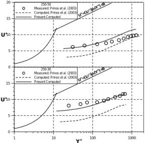
如前面文章所述,本研究所採用之巨觀模式所 提供的為流體充滿的多孔介質內的平均特徵,與微 觀模式結果或實驗資料比對可進一步瞭解與驗證 巨觀模式。目前有關紊流通過多孔介質底床的文獻 付之闕如,僅有的文獻Prinos et al. (2003)是探討紊 流通過多孔介質底床之特性,為達成此模式驗證的 目的,模式的計算條件乃設定與所能獲得的資料一 致。 Prinos et al. (2003)研究的渠道如圖 3 所示,渠 道幾何條件分別為長12m、寬 0.25m 與高 0.5m,文 中試驗組250-30 與 250-40 之試驗水深為 0.085m 與 0.095m,兩組試驗的多孔介質底床厚度 hp分別為 0.03m 與 0.04m,雷諾數 Rf分別為7581 與 10780, 多孔介質底床以與水流方向垂直且直徑D 為 10mm 非交錯排列的橫桿構成,多孔介質底床的孔隙率φ 為0.8286。表 1 為 Prinos et al. (2003)試驗的詳細條 件。 3.1 紊流過多孔介質底床 紊流通過多孔介質底床時純水區域紊流的流速 分 佈 如 圖 4 , 圖 中 的 紊 流 流 速 以 壁 座 標 (wall coordinates) Y+(= yU*/v)與 ( / ) * U u U+ = 表示以利 與Prinos et al. (2003)的微觀模式計算結果及試驗結 果直接比較,流體通過平滑且不透水底床時內區的 線 性 分 佈 Y+= U+ 與 外 區 的 對 數 率 分 佈 B Y U+=(1/κ)ln( +)+ (κ=0.41, B=5.25)亦繪於 圖中,由於底床為可透水之多孔介質,紊流可入侵 至多孔介質中,使純水區域之平均流速降低,因而 流速分佈偏離對數率分佈,由圖4 可看出本模式所 得多孔介質底床上方紊流流速分佈的數值結果與 實驗值吻合。圖5 為本模式與微觀模式計算結果及 試驗結果之無因次紊流能量k+ (=k/U*2)比較結 果,在純水區域本模式與微觀模式計算結果吻合; 在多孔介質區域本模式表現出將微觀模式平均化 之特性。值的一提的是本模式與微觀模式皆顯示紊 流能量有滲入多孔介質底床上方的特性,k+的極 大值產生於純水區域與多孔介質區域交界附近,從 試驗量測值亦可發現相同的趨勢,為量測值皆大於 本模式與微觀模式計算結果,這可能導因渠道寬身 比較小且Prinos et al. (2003)計算試驗k+值時採用 紊流能量k=0.5(u2+v2+w2)加以無因次化之結 果。五、分析與討論
本研究利用Prinos et al. (2003)試驗為基礎進行 紊流通過多孔介質底床之參數敏感度分析,計算進 行之雷諾數Rf皆與試驗相似,分析重點著重於多孔 介質底床對紊流特性之影響,因此分析之參數包括 孔隙率φ 與將滲透係數 K 無因次化表示之參數 Da (=K/ H2,達西數),計算之條件詳列於表 2 中。 圖6 為孔隙率與達西數對多孔介質上方壁座標表示 之紊流流速分佈的影響,流速分佈說明Da 值增大 (滲透係數增加)所伴隨的紊流滲入多孔介質底床 的情形亦增加,導致Da 值增大時多孔介質底床上 方的流場受影響較顯著,在外區的紊流流速分佈仍 維持馮卡門常數(von Kármán constant),但靠近交界 面的流速分佈則偏離對數率流速分佈,表示多孔介 質 底 床 上 方 的 流 速 分 佈 型 態 屬 於 混 合 層 型 態 (mixing layer type)而非一般的邊界層型態(boundary layer type)。另外一點需說明的是,如我們所期待的 當 孔 隙 率 增 加 時 流 入 多 孔 介 質 底 床 的 流 量 亦 增加,本文各數值試驗組皆採用相同流量,但使用摩 擦速度作為流速剖面無因次化之因子時,容易造成 孔隙率增加時流入多孔介質底床的流量有巨幅增 加的誤解,表 2 中流入多孔介質底床的流量值證 明,與孔隙率增加相比,多孔介質底床上方的流量 變化對Da 值增大較為敏感。 純水區域與透水區域內的無因次紊流能量k+ 分佈繪於圖7,分佈曲線說明在純水區域的k 值分+
佈小於Nezu and Nakagawa (1993)提出的紊流通過
平滑且不透水底床的經驗分佈曲線,k 值在透水+ 區域內的分佈顯示紊流能量的滲入多孔介質的情 形相當明顯,且與孔隙率或達西數的增加成正相關 的 關 係 , 在 達 西 數 最 大 之 方 案(Da=1.6×10⁻³, 8 . 0 = φ )中,k 值滲入達到+ y/hf =−0.35。對高孔 隙率或高達西數的多孔介質底床而言,k 值的滲+ 入情形說明在高透水性材料所組成的多孔介質, i k 傳輸方程式中的源項計算多孔介質內部紊流 能量分佈的重要性。此外,當孔隙率或達西數減小 時,多孔介質內部紊流能量分佈曲線顯示,透水的 多孔介質材料有慢慢轉變為不透水固體底床的趨 勢。 圖 8 為 孔 隙 率φ=0.8、 達 西 數 Da 介 於 3 10 6 . 1 × − ∼1.6×10⁻⁵以及達西數 Da=1.6×10⁻³、 孔隙率φ 介於 0.6∼0.8 時無因次紊流剪應力隨渠道 高程變化之情況,由圖中可明顯發現紊流剪應力滲 入至多孔介質底床上方之現象,而且此現象隨著孔 隙率與達西數增加而趨於明顯,這種交界面下方的 阻力增加效應主要是由純水區域與透水區域間的 動量交換所引起,因此紊流剪應力的影響對高滲透 性質的多孔介質材料相形重要,紊流剪應力可以改 變有機質的移動、沉積、有機反應過程以及氣體與 營養鹽的交換,圖8 中的結果說明當紊流通過透水 底床時,由於紊流剪應力滲入至多孔介質底床上方 將導致動量與質量有效的交換。為將紊流滲入至多 孔介質底床的情形有效量化,本研究定義紊流剪應 力滲入至多孔介質底床的深度d 為交界面至多孔pt 介質底床內紊流剪應力為零的距離,d 計算結果pt 列於表2 中並繪成圖 9,由圖 9 可清楚看出當孔隙 率φ 介於 0.6∼0.8 且達西數 Da 介於1.6×10⁻³∼ 5 10 6 . 1 × − 時d 分別與pt φ 及 Da 成正比之特性。
六、結論
本研究利用數值模擬研究完全發展流況下,二 維渠道內紊流通過多孔介質孔隙率φ 介於 0.6∼0.8 與達西數Da 介於1.6×10⁻³∼1.6×10⁻⁵所組成透水 底床時紊流之特性,可得到下列數點結論: 1. 由於流體於純水區域與透水區域交界面屬於 連續狀態,單一區域解法可用於計算此種混 合介質之流體運動。 2. 與紊流通過平滑且不透水底床比較,由於紊 流滲入多孔介質底床與動量交換的影響,使 的純水區域的流速明顯降低。 3. 紊流滲入多孔介質底床的現象與孔隙率或達 西數的增加成正相關,因此紊流滲入現象對 高滲透性多孔介質而言相形重要。 4. 對高透水性材料所組成的多孔介質而言,k i 傳輸方程式中的源項對決定k 值的分佈曲線+ 佔相當重要的地位。 5. 紊流剪應力滲入至多孔介質底床的深度dpt 可用於量化紊流滲入多孔介質底床的現象。六、參考文獻
1. Beavers, G. S. and Joesph, D. D. (1967). “Boundary conditions at a naturally permeable wall.” J. Fluid Mech., 30, 197–207.
2. Choi, C. Y. and Waller, P. M. (1997). “Momentum transport mechanism for water flow over porous media.” J. Env. Engrg., 123(8), 792-799.
3. de Lemos, M. J. S. and Pedras, M. H. J. (2001). “Recent mathematical models for turbulent flow in saturated rigid porous media.” J. Fluids Engrg., 123, 935–940.
4. Getachew, D., Minkowycz, W. J. and Lage, J. L. (2000). “A modified form of the k- ε model for turbulent flow of an incompressible fluid in porous media.” Int. J. Heat Mass Transfer, 43, 2909–2915.
5. Kuwahara, F., Kameyama, Y., Yamashita, S. and Nakayama, A. (1998). “Numerical modeling of turbulent flow in porous media using a spatially periodic array.” J. Porous Media, 1, 47–55.
6. Launder, B. E. and Sharma, B. I. (1974). “Application of the energy dissipation model of turbulence to the calculation of flow near a spinning disk.” Lett. Heat Mass Transfer, 3, 269–289.
7. Masuoka, T. and Takatsu, Y. (1996). “Turbulence model for flow through porous media.” Int. J. Heat Mass Transfer, 39, 2803–2809.
8. MacDonald, I. F., El-Sayed, M. S., Mow, K. and Dullien, F. A. L. (1979). “Flow through porous media: The Ergun equation revisited.” Ind. and Engrg Chemistry, 18, 199-208.
9. Mendoza, C. and Zhou, D. (1992). “Effect of porous bed on turbulent stream flow above bed.” J. of Hydraul. Engrg., 118(9), 1222-1240. 10. Miglio, E., Quarteroni, A. and Saleri, F. (2003).
“Coupling of free surface and groundwater flows.” Computers and Fluids, 32, 73-83. 11. Nakayama, A. and Kuwahara, F. (1999). “A
macroscopic turbulence model for flow in a porous medium.” J. Fluids Engrg., 121, 427–433.
12. Neale, G. and Nader, W. (1974). “Practical significance of Brinkman’s extension of Darcy’s law: Coupled parallel flows within a channel
and a bounding porous medium.” Can. J. Chem. Engrg, 52, 475– 478.
13. Patankar, S. V. (1980). Numerical heat transfer and fluid flow, Hemisphere, New York.
14. Pedras, M. H. J. and de Lemos, M. J. S. (2000). “On the definition of turbulent kinetic energy for flow in porous media.” Int. Commun. Heat Mass Transfer, 27(2), 211–220.
15. Pedras, M. H. J. and de Lemos, M. J. S. (2001a). “Macroscopic turbulence modeling for incompressible flow through undeformable porous media.” Intern. J. Heat and Mass Transfer, 44(6), 1081–1093.
16. Pedras, M. H. J. and de Lemos, M. J. S. (2001b). “Simulation of turbulent flow in porous media using a spatially periodic array and a low Re two-equation closure.” Numerical Heat Transfer, Part A, 39(1), 35–59.
17. Prinos, P., Sofialidis, D. and Keramaris, E. (2003). “Turbulent flow over and within a porous bed.” J. of Hydraul. Engrg., 129(9), 720-733.
18. Takatsu, Y. and Masuoka, T. (1998). “Turbulent phenomena in flow through porous media.” J. Porous Media, 3, 243–251.
19. Travkin, V. S. and Catton, I. (1995). “A two
temperature model for turbulent flow and heat transfer in a porous layer.” J. Fluids Engrg., 117, 181–188.
20. Vafai, K. and Thiyagaraja, R. (1987). “Analysis of flow and heat transfer at the interface region of a porous medium.” Int. J. Heat Mass Transfer, 30, 1391–1405.
21. Venkataraman, P. and Rama Mohan Rao, P. (1998). “Darcian, Transitional, and Turbulent Flow through Porous Media.” J. Hydraul. Engrg., 124(8), 840–846.
22. Vollmera, S., de los Santos, Ramosb F., Daebel H. and Kühn G. (2002). “Micro scale exchange processes between surface and subsurface water.” J. Hydrology, 269, 3-10.
23. Wang, H. and Takle, E. S. (1995). “Boundary-layer flow and turbulence near porous obstacles.” Boundary-Layer Meteorology, 74, 73–88.
24. Zhou, D. and Mendoz, C. (1993). “Flow through porous bed of turbulent stream.” J. Engrg. Mech., 119(2), 365-383.
25. Zippe, H. J. and Graf, W. H. (1983). “Turbulent boundary-layer flow over permeable and nonpermeable rough surfaces.” J. Hydraul. Res., 21(1), 51-65. 圖1 計算域與座標系統示意圖 i ϕ′ ϕ i ϕ′ i 4 4 4 4 4 4 4 4 4 3 4 4 4 4 4 4 4 4 4 2 1 ϕ 4 4 4 8 4 4 4 7 6 ϕ i 4 4 4 4 4 4 4 4 8 4 4 4 4 4 4 4 4 7 6 i ϕ i ϕ ϕ ′ ϕ 圖2 代表元素體(REV);雙平均的程序說明. 圖3 Prinos et al. (2003)的試驗渠道 1 10 100 1000 Y+ 0 5 10 15 U+ 250-30 Measured; Prinos et al. (2003) Computed; Prinos et al. (2003) Present Computed 0 5 10 15 20 U+ 250-50 Measured; Prinos et al. (2003) Computed; Prinos et al. (2003)
Present Computed U +=(1/κ) ln(Y +)+B U+=(1 /κ)ln(Y +)+B 圖4 透水底床上方流速分佈比較圖
7 0 1 2 k+ 3 4 5 -2.0 -1.8 -1.6 -1.4 -1.2 -1.0 -0.8 -0.6 -0.4 -0.2 0.0 0.2 0.4 0.6 0.8 y/hf 250-30
Measured; Prinos et al. (2003) Computed; Prinos et al. (2003) Present Computed -1.2 -1.0 -0.8 -0.6 -0.4 -0.2 0.0 0.2 0.4 0.6 0.8 1.0 y/hf 250-50
Measured; Prinos et al. (2003) Computed; Prinos et al. (2003) Present Computed 圖5 純水區域與透水區域紊流能力比較圖 1 10 100 1000 Y+ 0 5 10 15 U+ Da=1.6x10⁻³ Porosity=0.6 Porosity=0.7 Porosity=0.8 0 5 10 15 20 U+ Porosity=0.8 Da=1.6x10⁻³ Da=1.6x10⁻⁴ Da=1.6x10⁻⁵ U+=(1 /κ)ln(Y +)+B U+=(1 /κ)ln(Y +)+B 圖6 孔隙率與達西數對透水底床上方流速分 佈的影響 0 1 2 k+ 3 4 5 -1.0 -0.8 -0.6 -0.4 -0.2 0.0 0.2 0.4 0.6 0.8 y/hf Da=1.6x10⁻³
Nezu and Nakagawa (1993) Porosity=0.6 Porosity=0.7 Porosity=0.8 -1.0 -0.8 -0.6 -0.4 -0.2 0.0 0.2 0.4 0.6 0.8 1.0 y/hf Porosity=0.8 Nezu and Nakagawa (1993)
Da=1.6x10⁻³ Da=1.6x10⁻⁴ Da=1.6x10⁻⁵ 圖7 孔隙率與達西數對紊流能量的影響 0 0.2 0.4 -uv+ 0.6 0.8 1 -1.0 -0.8 -0.6 -0.4 -0.2 0.0 0.2 0.4 0.6 0.8 y/hf Da=1.6x10⁻³ Porosity=0.6 Porosity=0.7 Porosity=0.8 -1.0 -0.8 -0.6 -0.4 -0.2 0.0 0.2 0.4 0.6 0.8 1.0 y/hf Porosity=0.8 Da=1.6x10⁻³ Da=1.6x10⁻⁴ Da=1.6x10⁻⁵ 圖8 孔隙率與達西數對紊流剪應力的影響 0.04 0.06 0.08 0.10 0.12 0.14 0.16 0.18 dpt/ H 1.0 x10⁻⁵ 1.0 x10⁻⁴ 1.0 x10⁻³ 1.0 x10⁻² 1.0 x10⁻¹ Da 0.5 0.6 0.7 0.8 0.9 Poros ity 圖9 孔隙率及達西數與紊流滲入深度具高度 相關
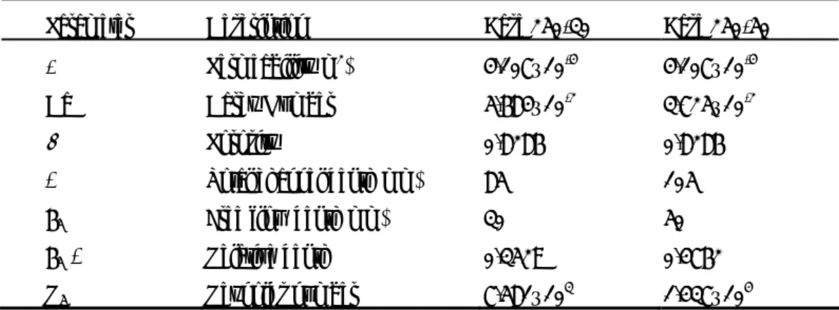
表1 Prinos et al. (2003)進行紊流通過透水底床之試驗條件
Parameter Description Case 250-30 Case 250-50
K Permeability(m2) 4.107×10⁻⁴ 4.107×10⁻⁴
Da Darcy Number 5.684×10⁻² 3.725×10⁻²
φ Porosity 0.8286 0.8286
H Total channel depth(mm) 85 105
hf Free flow depth(mm) 30 50
hf/H Relative depth 0.3529 0.4762
Rf Reynolds number 7.581×10³ 1.437×10⁴
表2 紊流與多孔介質之重要參數
Parameter Description Run1 Run2 Run3 Run4 Run5
K Permeability(m2) 1.0×10⁻⁴ 1.0×10⁻⁴ 1.0×10⁻³ 1.0×10⁻⁴ 1.0×10⁻⁵
Da Darcy Number 1.6×10⁻³ 1.6×10⁻³ 1.6×10⁻² 1.6×10⁻³ 1.6×10⁻⁴
φ Porosity 0.6 0.7 0.8 0.8 0.8
H Total channel depth(mm) 250 250 250 250 250
hf Free flow depth(mm) 125 125 125 125 125
hf/H Relative depth 0.5 0.5 0.5 0.5 0.5
Rf Reynolds number 1.187×10⁴ 1.183×10⁴ 1.140×10⁴ 1.175×10⁴ 1.197×10⁴
U* Friction velocity(m/sec) 0.00564 0.00649 0.00796 0.00778 0.00757
Qf /Qin Relative channel discharge 95.43 95.06 91.64 94.44 96.22
9