Fluid dielectric loading on leaky Lamb wave of a piezoelectric plate
Yung-Chun Leea兲 and Shi Hoa Kuo
Department of Mechanical Engineering, National Cheng Kung University, Tainan 701, Taiwan 共Received 7 April 2006; accepted 30 May 2006; published online 20 July 2006兲
This letter reports a high-precision wave measurement system for accurately determining the velocity of leaky Lamb wave. For an X-cut LiNbO3plate, the change in leaky Lamb wave velocity induced by fluid’s dielectric loading effect has been measured. The measured correlation between fluid’s permittivity and induced wave velocity variation has been compared with theoretical results obtained form partial wave theory. Good agreements are observed. Potential applications of this wave measurement system are addressed. © 2006 American Institute of Physics.
关DOI:10.1063/1.2234286兴
Free mode Lamb waves are guided waves propagating in a plate placed in vacuum or air so that both plate surfaces are traction-free. If one or both of the plate surfaces are in con-tact with a fluid, the guided plated waves become leaky Lamb waves for the wave energy is radiated into adjacent fluids through mechanical coupling at plate/fluid interfaces. Because of this fluid loading effect, a leaky Lamb wave is attenuated and has a phase velocity slightly different from that of a free mode Lamb wave. If the plate is piezoelectric, the electrical field inside the piezoelectric plate will also in-teract with adjacent fluids and cause energy radiation. There-fore, the characteristics of leaky Lamb waves of a piezoelec-tric plate are affected not only mechanically but also electrically by the adjacent fluid.
In recent years, leaky Lamb waves in piezoelectric plates subjected to fluid loadings have gained increasing interests since a number of sensing techniques have been developed based on the interaction mechanism between leaky Lamb waves and surrounding fluids.1,2This physical acoustic prob-lem has been analyzed theoretically by partial wave theory.3–6The theoretical works show that, for strong elec-tromechanical couplings, the fluid’s permittivity has signifi-cant influence on the wave velocities of leaky Lamb waves.6 As an example, Fig. 1 shows the calculated dispersion curves of S0 mode Lamb waves for a 0.5 mm thick X-cut LiNbO3 plate without fluid loading 共open兲 and with fluid loading from a pure ethanol共r= 26兲 or a pure water 共r= 80兲. The waves are propagating along an azimuthal angle of 40° mea-sured from the Y axis of the LiNbO3plate, in which direction the electromechanical coupling factor is known to be very large.6,7 It shows that the wave velocities are greatly influ-enced by fluid’s permittivity.
The goal of this work is to experimentally verify the relationship between fluid’s permittivity and leaky Lamb wave velocity predicted by partial wave theory. In reviewing earlier works on this issue,4–6 we find out that most of the experimental methods before measure the wave velocity it-self rather than the “change in wave velocity,” and therefore are neither sensitive nor accurate enough to resolve the issue. Other experimental methods2,8–11using interdigital transduc-ers共IDT兲 are more accurate and sensitive. However, the ex-citation and detection of acoustic waves using IDT are
strongly dependent on electromechanical coupling coeffi-cient, which is related to crystallographic orientation and wave propagating direction in the piezoelectric materials, and therefore may not be applicable when the couplings are weak.
In this work, a differential measurement system aiming at accurately determining the change in leaky Lamb wave velocity induced by fluid loadings is developed. The key element is a laboratory-made line piezoelectric transducer which consists of a long slender Pb共Ti,Zr兲O3共PZT兲 cermaic bar with a trapezoid cross section. The length, height, and widths in the bottom and top surfaces are 12.7, 0.5, 0.8, and 0.2 mm, respectively. The PZT bar is packaged with a copper block, tungsten/epoxy mixture, and a metal case, as well as electrically connected and shielded. It can act as an acoustic wave transmitter when applying electrical voltage to the PZT element or an acoustic wave receiver reversely.
As shown in Fig. 2, the proposed leaky Lamb wave mea-surement system is constructed using four line PZT transduc-ers. The transducers are mounted with a fixture共not shown兲 and are pressed against the sample plate under investigation, in this work an X-cut LiNbO3plate. The sample plate is also held by the fixture and can be oriented along different azi-muthal angle共兲 directions for wave propagation. Two PZT transducers are placed on opposite sides of the sample plate to form a transmitter pair and to excite acoustic waves in the plate. In a distance away from the PZT transmitters, another pair of line PZT transducers is deployed in a similar configu-ration for receiving acoustic waves. To operate the transmit-ting and receiving transducers for wave measurements, an electronic system consisting of an arbitrary wave form gen-erator, an electrical power amplifier, a signal preamplifier, a
a兲Author to whom correspondence should be addressed; electronic mail:
FIG. 1. Dispersion curves of Lamb waves in an X-cut LiNbO3plate along
40° azimuthal angle.
APPLIED PHYSICS LETTERS 89, 031920共2006兲
0003-6951/2006/89共3兲/031920/3/$23.00 89, 031920-1 © 2006 American Institute of Physics
digital oscilloscope, and a personal computer 共PC兲 is constructed.
As shown in Fig. 2, the sample plate under measurement is partially immersed in a fluid. The Lamb waves from the transmitters to the receivers can be divided into two parts. From the transmitters to the air/liquid interface, the acoustic wave is a free mode Lamb wave since there is no fluid load-ing. However, from the air/fluid interface to the wave receiv-ers, the waves become leaky Lamb waves subjected to fluid loadings. In Fig. 2, Lodenotes the distance between transmit-ters and receivers, and x the distance from receivers to the air/fluid interface. The time of flight of Lamb waves travel-ing from transmitters to receivers is
=Lo− x
co +x
c, 共1兲
where co and c are the phase velocities of free mode and leaky Lamb waves, respectively. During the measurements, the assembly of transmitters, receivers, and sample plate is always kept in the same configuration. However, the whole assembly is attached to a servo-controlled linear stage and hence can move vertically. The wave form measurements start from a small value of x and then gradually pushing the sample-plate/transducer assembly into the fluid for wave measurements. In Eq.共1兲, taking differentiation with respect to x gives c =
冋
d dx+ 1 co册
−1 . 共2兲Therefore, with given cothe leaky Lamb wave velocity can be determined from the linear correlation between change in time of flight共⌬兲 and change in distance x 共⌬x兲. It is estially a differential type of measurement which is very sen-sitive to the change in wave velocity and much less vulner-able to measurement errors and environmental noises.
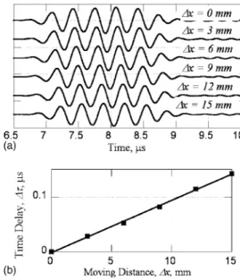
As an example, Fig. 3共a兲 shows the measured wave forms of the LiNbO3 plate along 40° azimuthal angle. The measurement was carried out in a tone-burst mode by apply-ing a 5-cycle, 3 MHz tone-burst signal to the transmittapply-ing transducers. With tone-burst frequency below cut-off fre-quencies of higher order modes we can focus on the S0mode only. The antisymmetrical A0 mode is not excited since the four PZT transducers are deployed and operated in a sym-metrical configuration. The sample plate is a 4 in. wafer and the distance between transmitters and receivers共Lo兲 is fixed to 47 mm which gives enough room to gate out waves re-flected from boundary. The air/fluid interface is initially 16 mm away from the receivers 共x=16 mm兲 and gradually increases step by step at an increment of 3 mm for wave form measurements. The data acquisition system共digital os-cilloscope兲 is triggered by the input driving signal and
there-fore provides a stable and common time reference point. The change in time of flight 共⌬兲 is equal to the time delay be-tween measured wave forms and can be easily determined. Figure 3共b兲 shows the linear correlation between ⌬and⌬x, and the slope of the linear fitting line of experimental data is used in Eq.共2兲 for determining leaky Lamb wave velocity. The obtained wave velocity is a phase velocity because the wave field is basically two dimensional and the time of flight is determined from the single-frequency sinusoidal signals rather than the wave forms’ envelopes.
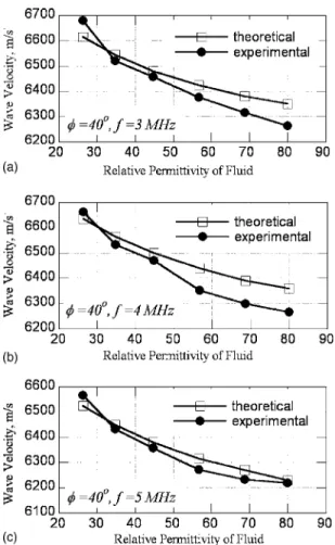
In order to investigate the influence of fluid’s permittiv-ity quantitatively, a number of fluids are prepared by mixing water and ethanol with different concentration ratios. Table I lists the measured mass density, wave speed, and permittivity of these fluids. Under the fluids’ loadings, the S0mode leaky Lamb waves propagating along the 40° direction in the LiNbO3 plate are measured at 3, 4, and 5 MHz. The mea-sured leaky Lamb wave velocities as functions of the fluid’s permittivity are displayed in Fig. 4. The theoretical data are also calculated from a computer program12 based on partial wave analysis. Good agreements between experimental and theoretical data are observed. The theoretical calculation has taken into account the variations of fluid’s mass density and wave speed. However, numerical results show that the fluid’s mechanical loadings contribute a maximum 2 m / s velocity variation and hence can be neglected as compared to the dielectric loading.
The measurements of leaky Lamb wave velocities have also been carried out on the same sample plate along the
FIG. 2. A differential measurement system of leaky Lamb waves.
FIG. 3.共a兲 Measured wave forms and 共b兲 linear correlation between change in time of flight共⌬兲 and change in distance x 共⌬x兲.
TABLE I. Measured material properties of water/ethanol mixed fluids. Weight ratio of ethanol共%兲 Relative permittivity Density 共kg/m3兲 Velocity 共m/s兲 100 26.31 800 1170 80 34.65 840 1310 60 44.71 880 1429 40 56.72 920 1563 20 68.68 960 1611 0 80 1000 1500
031920-2 Y.-C. Lee and S. H. Kuo Appl. Phys. Lett. 89, 031920共2006兲
direction of 150° azimuthal angle in which the piezoelectric coupling is known to be very weak.6,7 Theoretical calcula-tions show that the leaky Lamb wave velocities are almost unaffected by the fluid’s permittivity. The measured leaky Lamb wave velocities, as shown in Fig. 5, are independent of fluid’s permittivity and hence close to a constant value with a standard deviation around 12– 14 m / s. This agrees well with the theoretical results. Incidentally, the experimental data shown in Fig. 5 can be viewed as the measurement
uncer-tainty or repeatability of the proposed differential type wave measurement system.
In conclusion, we have developed a leaky Lamb wave measurement system based on the idea of differential mea-surement. The wave measurements are carried out under ex-actly the same mechanical and electrical conditions except for the relative traveling distances between free and leaky waves. Therefore, it is very accurate in measuring velocity difference between free and leaky Lamb waves and we have determined the velocity variation induced by fluid’s permit-tivity. The experimental results agree well with the theoreti-cal ones theoreti-calculated from partial wave theory. The proposed measurement method can be applied to a number of leaky acoustic wave problems on almost all kinds of materials.
1D. S. Ballantine, R. W. White, S. J. Martine, A. J. Ricco, E. T. Zellers, G.
C. Frye, and H. Wohltjen, Acoustic Wave Sensors: Theory, Design, and
Physico-Chemical Applications共Academic, London, 1997兲.
2F. Josse, Z. A. Shana, D. T. Haworth, S. Liew, and M. Grunze, Sens.
Actuators B 9, 97共1992兲.
3A. H. Nayfeh, Wave Propagation in Layered Anisotropic Media共Elsevier,
New York, 1995兲.
4C.-H. Yang and D. E. Chimenti, J. Acoust. Soc. Am. 97, 2103共1995兲. 5C.-H. Yang and D. E. Chimenti, J. Acoust. Soc. Am. 97, 2110共1995兲. 6C.-H. Yang and Y.-A. Lai, Jpn. J. Appl. Phys., Part 1 43, 2004共2004兲. 7I. E. Kuznetsova, B. D. Zaitsev, S. G. Joshi, and I. A. Borodina, IEEE
Trans. Ultrason. Ferroelectr. Freq. Control 48, 322共2001兲.
8K. Motegi and K. Toda, Jpn. J. Appl. Phys., Part 1 38, 3032共1999兲. 9A. Sawaguchi and K. Toda, Jpn. J. Appl. Phys., Part 1 30, 2402共1991兲. 10F. Josse and Z. A. Shana, IEEE Trans. Ultrason. Ferroelectr. Freq. Control
39, 512共1992兲.
11B. D. Zaitsev, I. E. Kuznetsova, S. G. Joshi, and I. A. Borodina,
Ultrason-ics 39, 45共2001兲.
12Y.-C. Lee and S. H. Kuo, J. Appl. Phys.共to be published兲.
FIG. 4. Experimental and theoretical leaky Lamb wave velocities at 共a兲 3 MHz,共b兲 4 MHz, and 共c兲 5 MHz.
FIG. 5. Measured leaky Lamb wave velocities along the direction of 150° azimuthal angle.
031920-3 Y.-C. Lee and S. H. Kuo Appl. Phys. Lett. 89, 031920共2006兲