國立臺灣大學電機資訊學院電機工程學研究所 碩士論文
Graduate Institute of Electrical Engineering
College of Electrical Engineering and Computer Science National Taiwan University
Master Thesis
智慧服務機器人基於遞迴類神經網路進行 未知室內語意導航之研究
Unknown Indoor Semantic Navigation Based on
Recursive Neural Network for Intelligent Service Robotics
陳長鈞
Chang-Jiun Chen
指導教授:羅仁權 博士 Advisor: Ren.C. Luo, Ph.D.
中華民國 106 年 7 月 July 2017
誌謝
就讀碩士班的這兩年是我人生中一段美好的回憶。時光匆匆飛逝,一轉眼就 到了鳳凰花開的時刻。特別感謝父母親辛苦地栽培與教誨,給予我支持與鼓勵,
讓我能夠無憂無慮地專心於課業上。感謝我的指導教授羅仁權教授,提供我們豐 富的資源以及在研究過程與論文的指導,同時培養我們大至國際觀、小至做人處 事的道理。過程中所經歷的一切都是一輩子難得的體驗,也從其中學到非常多寶 貴的知識與經驗。二年的碩士生涯中,老師充分地展現出國際級專家學者的風範 與視野,不僅帶領我們探索學術知識上的深度與廣度,更給予我們充分的機會去 體驗研究以外的經驗,期望我們成為均衡發展的人才。在待人處事方面,老師更 是教給我們許多社會上應對進退的準則,這一切都使我獲益良多。
在國立臺灣大學智慧機器人及自動化國際研究中心(NTU- iCeiRA)兩年的研 究生活中,我要感謝鐿文、瑋隆、東榕、繼棠、金成、昕昳、旭佳、禮聰、志遠、
献章等博班學長;他們不僅不厭其煩的給我指導,並且也教我如何自己摸索出問 題的答案。還要感謝碩班學長銘駿、建安、士紘、煒森、文謙、金博、建偉、冠 志、柏宏、榮育,從優秀的學長們身上我學到很多,也常把他們當做努力的榜樣,
期許自己也能跟學長們一樣厲害。更不能忘記同屆一起努力奮鬥的伙伴俊豪、莉 彤、李晟、晴岡、靖霖、昱佑、達方、凱鈞、仲凱、孟勳、柏凱,和你們一起窩 在實驗室,不論是做研究、忙比賽還是一起玩樂,都是我碩班生涯最快樂的事情 之一。謝謝積極認真又貼心的學弟妹們,培淳、石崴、武昱、嵩詠、智堅、威辰、
錦賢、育榕、育澤、名彥、展嘉、何鑫、王昊、曾旻,幫忙大大小小的事務,一 起打球運動。也要感謝默默在背後幫我們完成許多瑣事的雯雅 (Tracy) 、煜倫 (Dornin)、姿伶(Amy)、芳嫻 (Helen)、佩芸(Winnie)等助理們。
最後,感謝我的朋友們在背後給予我莫大的鼓勵,你們的存在是我前進的動 力,希望我們的友誼能夠持續一輩子。能完成這篇論文,我要感謝在我生命中出 現的每一個人,真的非常謝謝你們。
陳長鈞 謹誌
中文摘要
近年的研究已經讓服務型機器人具備能在複雜的室內環境中移動之功能。然 而,這些技術往往需要根基於事先建立好的環境地圖,因而無法應用在未知的環 境中。與此相對,人類在進入未知的環境時,常依靠問路這一方法,來得知如何 抵達某一地點,並進一步移動到該處。目前的移動型機器人,尚缺乏這種依據接 收到的口頭指令,在未知的環境中導航的能力。
在本研究中,我們的目標是將於未知環境中導航的功能,實作在移動型機器 人上。我們以室內環境作為主體,利用遞迴類神經網路的方法,讓機器人學習人 類導航的方法。我們設計了一個導航系統,並以人類的導航紀錄和相對應的導航 指令來訓練此系統。我們將導航指令進行分割,並將每個切割出來的簡單指令分 類到十個我們所定義的基本指令集當中;而每筆人類的導航紀錄,都是根據某一 類基本指令來進行收集的。在訓練類神經網路模型的過程中,我們更提出一驗證 的方法來檢驗訓練之模型的有效性。
最後,我們在模擬和實際的環境中測試此導航系統。我們在搬運機器人「企 鵝」上實作我們的系統,並實驗其是否能根據不同的導航指令,移動到對應的地 點。我們將機器人的移動路徑,與接受同樣指令的人類所走出來的路徑進行比較;
而結果顯示,基於此一導航系統的移動型機器人,能達到接近於人類的導航表現。
關鍵字:服務型機器人,移動型機器人、語意式導航、機器人深度學習、人機互 動
ABSTRACT
Recent researches have made service robots capable of navigating through complex and clustered indoor environments. However, such techniques require prebuilt maps and cannot be applied to unknown environments. By contrast, when entering an unknown environment, humans can ask someone for directions to figure out how to get to a specific location, and further navigate to the destination by following the instructions. Present mobile robots lack the ability of navigating under unknown environments according to the given verbal instructions.
In this research, we aim to implement the ability of navigating through unknown environments on mobile robots. We focus on indoor environments, using recursive neural networks to make robots learn the methods of navigating from humans. We design a navigation system, which is trained by human-controlled navigating records along with instructions. Instructions are split and then classified into ten basic classes, and each navigating record is collected according to one of these basic instruction classes. During the training process, we propose a validating method to evaluate the effectiveness of our models.
Finally, we put our system to the test under both simulation and real environments.
We implement the system on a warehouse robot called ‘Penguin’, and test whether it can get to desired positions according to different given instructions. We compare the navigation paths of our mobile robot with those of humans following the same verbal instructions. The results show that our mobile robot can achieve similar performance to that of humans.
Keywords: service robotics, mobile robotics, semantic navigation, deep learning in robotics and automation, human-robot interaction
CONTENTS
口試委員會審定書
誌謝 ...i
中文摘要 ... ii
ABSTRACT ... iii
CONTENTS ... v
LIST OF FIGURES ... viii
LIST OF TABLES ... x
Chapter 1 Introduction ... 1
1.1 Problem Statement ... 1
1.2 Related Works ... 4
1.3 Research Objective ... 6
1.4 Thesis Structure ... 7
Chapter 2 System Architecture ... 8
2.1 Hardware Specifications ... 8
2.1.1 Motors ... 9
2.1.2 Sensor ... 10
2.1.3 Central Control Computer ... 14
2.1.4 Power Supply System ... 16
2.2 Software Architecture ... 18
2.2.1 Overview ... 18
2.2.2 Laser Range Finder Layer ... 20
Interpolation ... 20 2.2.2.1
2.2.3 Instruction Layer... 23
Speech Recognition ... 24
2.2.3.1 Conversion ... 24
2.2.3.2 2.2.4 Neural Network Model ... 25
2.2.5 Post-processing Layer ... 26
Speed Adjusting Function ... 26
2.2.5.1 Halting Counter ... 27
2.2.5.2 Chapter 3 Training Data Set ... 29
3.1 Instruction ... 29
3.2 Basic Instruction Sets ... 32
3.3 Human-Controlled Navigating Records ... 36
3.3.1 Database... 36
3.3.2 Teleoperation Program ... 37
3.4 Features and Advantages ... 39
Chapter 4 Training and Experiments ... 41
4.1 Training Models ... 41
4.1.1 Implementation ... 41
4.1.2 Validation ... 42
4.1.3 Monitors ... 43
4.2 Experiments and Results... 45
4.2.1 Simulation ... 45
4.2.2 Real Environment ... 45
4.2.3 Interpolation ... 46
4.2.4 Comparisons ... 52
REFERENCE ... 57 VITA ... 62
LIST OF FIGURES
Fig. 1.1.1 Navigating under unknown indoor environment ... 2
Fig. 1.1.2 Example of expressing a navigation path by different instructions ... 3
Fig. 2.1.1 iCeiRA warehouse robot ‘Penguin’ ... 8
Fig. 2.1.2 Servomotors and motion controllers ... 9
Fig. 2.1.3 Different environment structures observed from laser range finder ... 11
Fig. 2.1.4 Two series of Laser Range Finder being used in our research ... 14
Fig. 2.1.5 Control diagram of navigation system ... 16
Fig. 2.1.6 The overall circuit diagram implemented onboard ... 17
Fig. 2.1.7 DR-UPS40 by Mean Well ... 18
Fig. 2.2.1 Structure of our navigation program ... 19
Fig. 2.2.2 Executing process of our navigation system ... 20
Fig. 2.2.3 Modified saturation function ... 23
Fig. 2.2.4 Structure of neural network model ... 25
Fig. 3.1.1 Ten paths corresponding to ten classes of simple instructions ... 31
Fig. 3.1.2 Example of executing a complex instruction ... 32
Fig. 3.2.1 Process of generating a complete instruction sentence ... 33
Fig. 3.3.1 Example of the recording files ... 37
Fig. 3.3.2 Control method of teleop_twist_keyboard ... 38
Fig. 3.3.3 Control keys of our teleoperation program ... 39
Fig. 4.1.1 Loss monitor and validation monitor ... 44
Fig. 4.2.1 Floor plans of Building for Research Excellence ... 47
Fig. 4.2.2 Screenshot of the demonstration video ... 48
Fig. 4.2.3 Experiment results of Class 1 and Class 2 instructions ... 49
Fig. 4.2.4 Experiment results of Class 3 and Class 4 instructions ... 50 Fig. 4.2.5 Experiment results of Class 5 and Class 6 instructions ... 51 Fig. 4.2.6 Experiment results of Class 7 and Class 8 instructions ... 52
LIST OF TABLES
Table 2.1-1 Technical specifications of Hokuyo UTM-30LX ... 12
Table 2.1-2 Technical specifications of Hokuyo URG-04LX ... 13
Table 3.1-1 Class of simple instructions ... 30
Table 4.2-1 Success rate of each basic instruction ... 48
Chapter 1 Introduction
1.1 Problem Statement
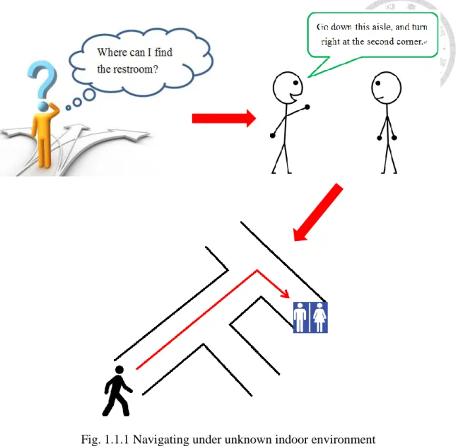
Suppose you are attending an interview in an office building. During the break you need to go to the restroom. However, since it is the first time you have been to this location, you do not know the direction. You might look for a floor plan or signs to find your way, or ask someone for directions. In the latter case, you may receive straightforward instructions, such as ‘You just go down this aisle and turn left at the second corner, and you will see it.’ Even though you had never walked along this path, nor had you seen the map, you are still able to reach the destination by following the instruction. In our daily life, we often ask for directions to find out how to get to specific locations. Humans possess the ability to navigate through unfamiliar environment according to simple instructions. By contrast, can robots achieve the same thing?
To execute a variety of tasks, service robots often need to have the ability of navigating and avoiding obstacles under different environments. Many methods have been developed to achieve this, including the effective simultaneous localization and mapping (SLAM) algorithms. Although these kinds of algorithms can make mobile robots navigate to destinations properly, they all depend on the understanding of the entire environment. In other words, robots need to construct the map of environment before starting to conduct their missions. On the other hand, exploration algorithms let robots able to navigate and construct maps under unknown environments. However, these algorithms cannot command robots to explore specific locations. Therefore, there has not been any algorithm that can have robots move to desired locations to execute
Fig. 1.1.1 Navigating under unknown indoor environment
In addition to the necessity of building maps for navigation, to let robots understand the navigating instructions from human, the efficient communication between human and robots is also a critical issue. Maps that robots use for localization and navigation, such as occupancy grid map, lack semantic information. Meanwhile, it is not easy to express natural language by mathematical models. To solve these problems, researches have been done to construct semantic maps for users. Robots classify their positions into different locations, such as corridors, halls or room 302, adding semantic information to the maps. Other researches establish probabilistic models for the instructions written in commonly verbal expressions, helping the control
system of robots handle the uncertainty and ambiguity inside human verbal instructions.
Nonetheless, due to the variety and complexity of verbal instructions, it is hard to express all the possible patterns of instructions in mathematical models. For example, we can clearly see that the following two instructions refer to the same navigation path according to the map shown in Fig. 1.1.2, although they are expressed in such different ways:
Go straight to the end, turn right, and then enter the second room on your left hand side.
You just turn right at the end of this aisle, and then turn left at the second entry.
It is proper to claim that there are thousands of ways to express a same navigation path, and building models for all of them is impossible. Therefore, constructing an efficient algorithm for mobile robots to understand instructions received from human and execute navigation is never a simple work.
The problem we want to solve in our research has two aspects. First, robots cannot navigate to a certain location before constructing a map of the unknown environment.
Second, it is hard for robots to follow human commands due to the complexity and variety of verbal instructions. Therefore, our question is: Given an indoor environment which is unknown to a mobile robot, can the robot navigate to a certain location by following human verbal instructions?
Before we describe the detailed objectives of this research and our method for the above question, we will first discuss some previous researches related to this topic in the next section.
1.2 Related Works
Moving to a specific location according to semantic instructions is a very intuitive way of navigation for mobile robots. However, this is never an easy task. To have robots efficiently use semantic information, a method using topological-semantic-metric map and Bayesian models is proposed to construct semantic maps for human-like navigation [1]. The direction of moving is computed from probabilistic models, and obstacles are avoided during semantic navigation. This research shows a great success in navigating robots to goal positions using symbolic descriptions.
An abstract map is implemented to represent unseen environments for mobile robots to navigate using only symbolic language phrases [2]. In addition, another research aims to plan semantic paths for human by integrating multiple sensors and using results from simultaneous localization and mapping (SLAM) algorithms [3].
These researches all try to bridge the gap between verbal instructions human use for instructing and mathematical models machines use for executing tasks.
To construct efficient communication between human and robots, many researches
use the methods of machine learning to do semantic mapping under indoor environments, classifying positions into different locations for human to understand easily. A supervised learning algorithm—Adaboost, has been used to classify each position into corridor, room or doorway [4]. They use 2D laser range finders as sensors, and have the system recognize environmental shapes around the position. Some researches afterward improve the performance of it. K-means and Learning Vector Quantization methods, as well as the Markov model have been used to improve the classification rate of door [5]. A learning algorithm using the classification results from SVM and CRF is proposed, and experiments have been conducted on various environments to demonstrate its performance over real-world task [6]. In addition, different kinds of sensors are used to classify the location more precisely. A place categorization system is built upon convolutional network, and its accuracy has been evaluated using 3 different types of cameras [7]. The convolutional neural network is also applied to classify places, where LIDAR sensor is used to create occupancy grids data [8]. These efforts are all successful in adding semantic information to known or new environments.
While moving to unknown places, predicting the location we are about to enter helps us decide the next action to be taken. For example, if we want to go to room 305, and we have seen room 301, 302 sequentially, we may assume that our direction is correct, and we need to walk through the aisle and pass by two more rooms before seeing our destination. This predicting ability allows us to avoid wasting time on searching more information about the environments, such as entering room 304 to check whether it is the correct one. Researchers implement this predicting ability on mobile robots to improve the performance of mapping, localization and navigation. An
the built map of explored regions to decide whether there is a similar structure inside the unexplored regions. Besides, similarities between current surroundings and built map have been used to actively predict close loops in unexplored areas and reduce the uncertainty during exploration [10].
1.3 Research Objective
In this research, our motivation is to make the robot ‘understand’ human verbal instructions used in navigation instructions, and move to the corresponding destinations without having any pre-knowledge about the indoor environment. We now specify the detailed objectives we aim to achieve, as well as the methods we plan to use.
We design a navigation system, which can be applied on our mobile platform. This system receives verbal instructions from humans, and controls the robot to navigate through unknown environments in both simulation and real world.
We use the method of machine learning to construct the main body of our navigation system. The neural network model is trained to learn the way human navigate according to some instructions.
The neural network model takes instructions and data acquired by sensor as its input, and outputs moving and rotating velocity commands to the mobile robot, instead of local or global goal positions in the environment.
We give restrictions to the instructions applied in this research. They need to be a certain type of instructions, and they should be legal. A legal instruction is defined to be an instruction that can be successfully execute under the given environment.
For example, if you cannot turn right ahead, then an instruction telling you to turn right at the front is not legal. We will explain the type of instructions we consider in Chapter 3.
Sensor we choose should be able to recognize the structures of indoor environments. We choose to use 2D laser range finder as our sensor, and we will explain our reasons in Chapter 2.
We use navigation records to train our neural network model. These records, called human-controlled navigating records, are generated by manually control robots to navigate by different people.
We train our model using data collected in simulation, and the navigation system should be able to apply in real environment.
By achieving the above objectives, we aim to give a proper solution to the stated question.
1.4 Thesis Structure
In Chapter 2, we introduce the system architecture, including the specifications of hardware components we use on our experiment platform, and the structure of presented software. Chapter 3 describes the training data set we use to train our neural network model. We will also describe the categories of instructions we consider in our research, as well as our method of collecting training data.
In Chapter 4, we introduce the process of training our neural networks, and the method we use to validate the efficiency of models. Next, we describe the details of experiments conducted under simulation and real environments. We will analyze the results and do some comparisons to examine the performance of our navigation system.
Finally, Chapter 5 provides conclusions to our effort, explains the contributions of this research, and discusses the future works.
Chapter 2 System Architecture
In this chapter, we first introduce the hardware we use to test our navigation system. We will describe the specification of each component on the mobile platform, including motors, sensors, control computer and the power supply system. We will also explain the reasons for choosing these components, as well as our concerns while designing this platform. In the second part of this chapter, we describe the software architecture. Our navigation system consists of several functional layers and the recursive neural network model. We will introduce the function of each layer, and how we implement these layers.
The structure of our neural network model will also be discussed.
2.1 Hardware Specifications
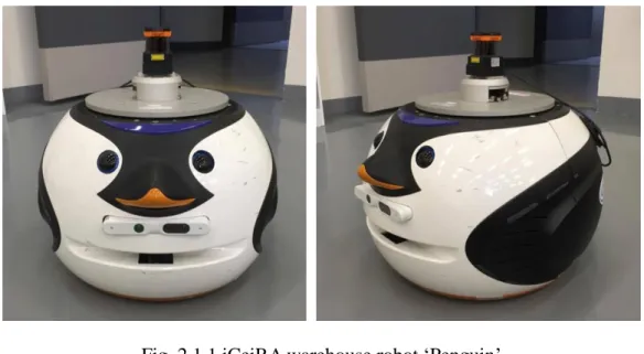
In this research, we implement our navigation system on the warehouse robot called ‘Penguin’, which is shown in Fig. 2.1.1. This robot is equipped with two differential wheels, one laser range finder mounted at the top, an Xtion Pro Live RGB-D camera, and a central control computer. In the following paragraphs, we will describe the specifications of these components.
Fig. 2.1.1 iCeiRA warehouse robot ‘Penguin’
2.1.1 Motors
The warehouse robot has two differential wheels and two omnidirectional wheels served as passive wheels. The former are driven by two Faulhaber 4490H048B Brushless DC-Servomotors with reduction of 66:1. Each servomotor is connected to a corresponding MCBL 3006 Motion controller. The motion controllers are connected via a RS232-USB signal cable to the CPU’s USB port.
We set the maximum speed of two motors to be 10000rpm via motion controllers. The gear ratios of two differential wheels are both 3, thus the overall gear ratio is equal to 200. Radius of the differential wheel is 0.075m. Therefore, the theoretical maximum velocity of our robot is approximately 0.4m/s. However, due to robot’s weight the maximum velocity will be smaller in practice. This specification is used when collecting training data and training our neural network models.
The wheel odometry is attached on the servomotor. We are not completely certain which kind of encoder has been mounted on the servomotors, but the documentation suggests the servomotor model type can co-operate with two-channel or three-channel optical or magnetic encoders.
(a) Faulhaber 4490H048B (b) MCBL 3006 Fig. 2.1.2 Servomotors and motion controllers
2.1.2 Sensor
We only use the laser range finder to gather information form the environment. The RGB-D camera is not used in our research. We now explain why we choose to use laser range finder as the main sensor.
To get a well-trained neural network model, it is essential to prepare a sufficient amount of training data. However, collecting data in real environments is time-consuming and difficult, especially when we want to record the entire navigation process. Therefore, we aim to collect our training data under simulation environment. In such case, using laser range finder as sensor has many advantages.
First of all, the amount of data returned by a laser range finder is much less than that by other sensors, such as camera. As a result, speed of calculation become faster, and delay of navigation system is prevented.
Next, although the amount of data is small, it is sufficient to realize the structure of indoor environment through laser range finder. We take Fig. 2.1.3 as an example. A mobile robot is navigating through an indoor environment, and the collected sensor data is visualized in rviz, a 3D visualization tool of ROS. From Fig. 2.1.3 (a), we can tell that the robot is moving along a corridor, while Fig. 2.1.3 (b) shows that there is a crossroad in front of the robot. Thus, robots and humans can decide their actions according to the sensor measurements.
Last but not least, the effect of noise on laser range finder is small. The sensor measurements collected from simulation environments have similar performance to those from real environments. Therefore, it is appropriate to train our system using the records collected in simulation, and test it in the real world. In contrast, if we use camera as the main sensor, the training process will be completely different. We cannot
use simulation images to train out navigation model, since the situation varies a lot in real world due to several factors, such as influence of light.
To sum up, we consider laser range finder an appropriate sensor to achieve this navigation task. The structures of indoor environments can be observed, and training can be done using simulation data without considering the effect of noise.
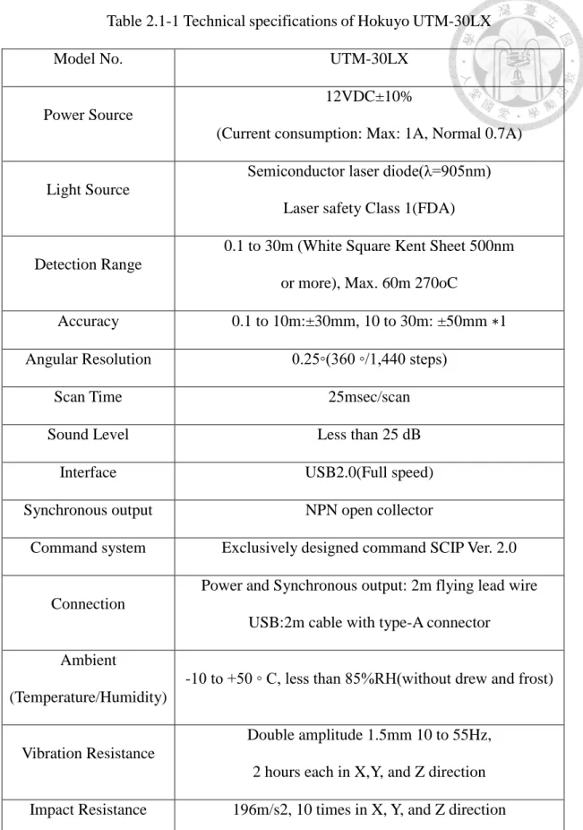
The laser range finder we use in our research is Hokuyo UTM-30LX. Table 2.1-1 describes its technical specifications. It should be noticed that UTM-30LX has a scanning range of 270 degrees. If we place the laser range finder at the front of our warehouse robot, both sides of it will be blocked by the robot. This will results in being unable to get the full scanning range. Therefore, we mount the laser range finder on top of the mobile robot. Height of the sensor is 45cm from ground.
(a) Corridor (b) Crossroad Fig. 2.1.3 Different environment structures observed from laser range finder
Table 2.1-1 Technical specifications of Hokuyo UTM-30LX
Model No. UTM-30LX
Power Source
12VDC±10%
(Current consumption: Max: 1A, Normal 0.7A)
Light Source
Semiconductor laser diode(λ=905nm) Laser safety Class 1(FDA)
Detection Range
0.1 to 30m (White Square Kent Sheet 500nm or more), Max. 60m 270oC
Accuracy 0.1 to 10m:±30mm, 10 to 30m: ±50mm ∗1 Angular Resolution 0.25◦(360 ◦/1,440 steps)
Scan Time 25msec/scan
Sound Level Less than 25 dB
Interface USB2.0(Full speed)
Synchronous output NPN open collector
Command system Exclusively designed command SCIP Ver. 2.0
Connection
Power and Synchronous output: 2m flying lead wire USB:2m cable with type-A connector
Ambient
(Temperature/Humidity)
-10 to +50 ◦ C, less than 85%RH(without drew and frost)
Vibration Resistance
Double amplitude 1.5mm 10 to 55Hz, 2 hours each in X,Y, and Z direction Impact Resistance 196m/s2, 10 times in X, Y, and Z direction
Weight Approx. 370g (with cable attachment)
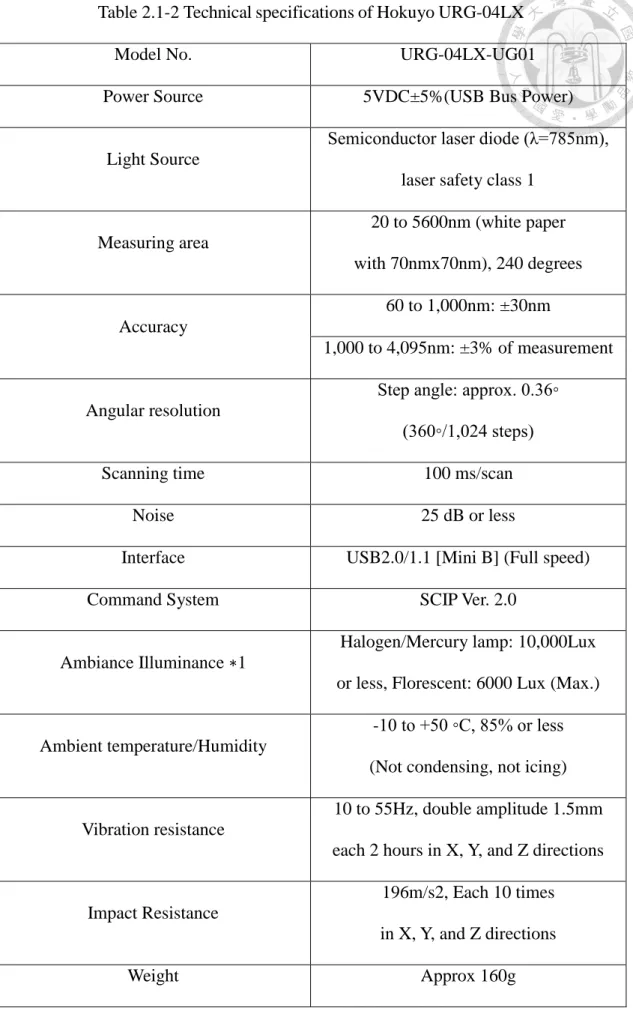
Table 2.1-2 Technical specifications of Hokuyo URG-04LX
Model No. URG-04LX-UG01
Power Source 5VDC±5%(USB Bus Power)
Light Source
Semiconductor laser diode (λ=785nm), laser safety class 1
Measuring area
20 to 5600nm (white paper with 70nmx70nm), 240 degrees
Accuracy
60 to 1,000nm: ±30nm
1,000 to 4,095nm: ±3% of measurement
Angular resolution
Step angle: approx. 0.36◦
(360◦/1,024 steps)
Scanning time 100 ms/scan
Noise 25 dB or less
Interface USB2.0/1.1 [Mini B] (Full speed)
Command System SCIP Ver. 2.0
Ambiance Illuminance ∗1
Halogen/Mercury lamp: 10,000Lux or less, Florescent: 6000 Lux (Max.)
Ambient temperature/Humidity
-10 to +50 ◦C, 85% or less (Not condensing, not icing)
Vibration resistance
10 to 55Hz, double amplitude 1.5mm each 2 hours in X, Y, and Z directions
Impact Resistance
196m/s2, Each 10 times in X, Y, and Z directions
To verify that our navigation system could be implemented on different mobile platform, we conduct experiments in simulation using mobile robot equipped with other type of laser range finder. The laser range finder we use here is URG-04LX. Table 2.1-2 describes its technical specifications. It should be noticed that the scanning range and the number of measurement steps of URG-04LX are different from those of UTM-30LX. To make our neural network model work properly, some efforts need to be done to eliminate this difference. We will describe the method we use in the software section.
(a) Hokuyo UTM-30LX (b) Hokuyo URG-04LX Fig. 2.1.4 Two series of Laser Range Finder being used in our research
2.1.3 Central Control Computer
Our central control computer is the Jetson TX1 Developer Board. Its main function is to control the robot movement and receive sensor data. On the central control computer we run the Robot Operating System (ROS) [11]. Two major ROS nodes are used to achieve such tasks.
ros_control [12]
In brief, it controls the rotation of two wheel motors. Our navigation program, as well as the teleoperation program, publishes the command velocity to this node.
And then, ros_control calculates the corresponding rotational speeds of two differential wheels and the driving servomotors.
hokuyo_node [13]
This node handles the sensor data acquired from 2D laser range finder. Some parameters in this node can be adjusted to deal with the situation of using different laser range finders, where the detection ranges and angular resolutions are both different.
In addition to these two nodes, the ROS node teleop_twist_keyboard is used to remotely control the robot while our navigation program is not running [14]. It serves as a teleoperation program, however in the next chapter we will mention that we design our own teleoperation program and the reason for doing that.
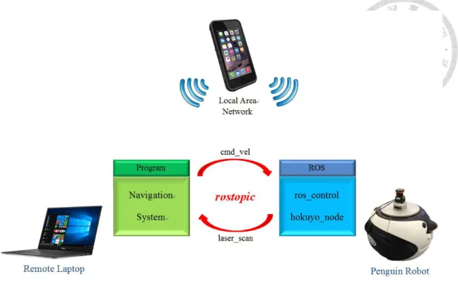
To conduct our experiments more efficiently, we run our navigation program on a remote computer so that we can modify our program immediately. The central control computer and the remote computer are connected to the same local area network.
Through the network ROS node hokuyo_node publishes readings of the laser range finder to the remote laptop, and after computation our navigation program publishes the command velocity back to ros_control node. Our program is packaged in a ROS node, and the exchange of messages is achieved through ROS topics.
The local area network can be provided by a cellphone. Fig. 2.1.5 shows the control diagram of our navigation system.
Fig. 2.1.5 Control diagram of navigation system
2.1.4 Power Supply System
The electric circuit used on-board consumes exclusively DC current, which means that any AC flow should be converted to DC flow previous to usage, and thus we deploy a DC Power Supply unit to import appropriate voltage and current flow. Normally the power system is supplied no more than 30V and 6A. If the supplied current exceeds that upper bound, fuse and UPS may serve as buffers and safety measure. The power system is designed under the following prerequisites:
Safety first
Ease of maintenance. All input/output ports are located at the rear of the robot.
The circuit should be as precise and succinct as possible containing only necessary components.
When connected to external power supply, the circuit works as one single close- loop. Such design ensures that the batteries are safely and efficiently charged and
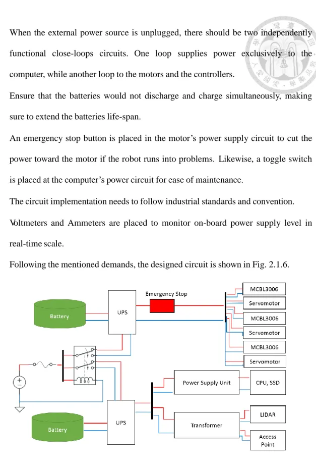
When the external power source is unplugged, there should be two independently functional close-loops circuits. One loop supplies power exclusively to the computer, while another loop to the motors and the controllers.
Ensure that the batteries would not discharge and charge simultaneously, making sure to extend the batteries life-span.
An emergency stop button is placed in the motor’s power supply circuit to cut the power toward the motor if the robot runs into problems. Likewise, a toggle switch is placed at the computer’s power circuit for ease of maintenance.
The circuit implementation needs to follow industrial standards and convention.
Voltmeters and Ammeters are placed to monitor on-board power supply level in real-time scale.
Following the mentioned demands, the designed circuit is shown in Fig. 2.1.6.
Fig. 2.1.6 The overall circuit diagram implemented onboard
We use relay as an automated and analogue switch to link and break both loops of
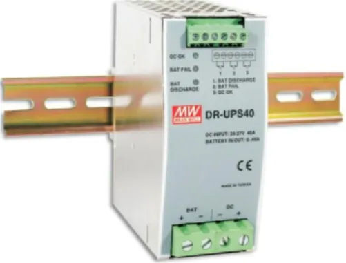
live wires supply the current for sub-loops with roughly the same voltage. For each loop, the first node to connect with the main power supply is located at the Uninterrupted Power Supply (UPS). By connecting in a redundant manner, the UPS not only serves as an intermediary hub for supplying the load, but also to charge and discharge the batteries, hence playing an intermediary and buffer role of power regulator between the main power source, the battery and the load. Considering the reliability, robustness, and durability of such key role, we utilized one DR-UPS40 for each sub-circuit.
Fig. 2.1.7 DR-UPS40 by Mean Well
2.2 Software Architecture
2.2.1 Overview
Fig. 2.2.1 shows the overall structure of our navigation program. It is composed of one neural network model and several processing layers. We will describe functions of these components later.
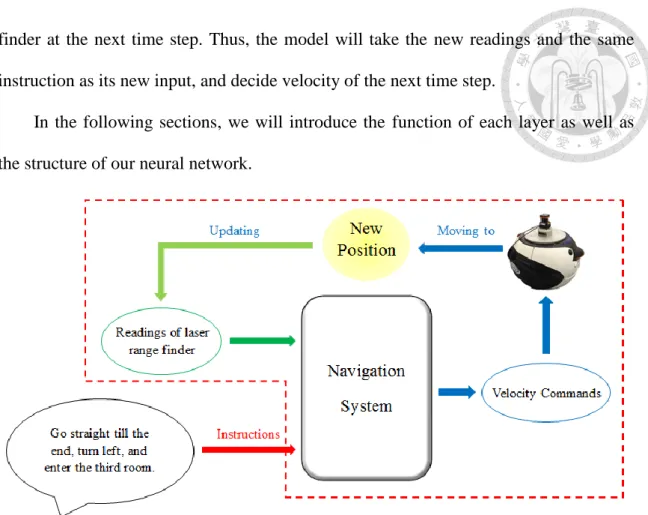
Fig. 2.2.2 shows the executing process of our navigation system. At a certain time step, the navigation system takes the current laser range finder readings, as well as the instruction given by user as its input. After computing it outputs the desired moving and rotating velocity of mobile robot. The robot will navigate in the given speed for a time period, entering a different position. This leads to different readings of the laser range
Fig. 2.2.1 Structure of our navigation program
finder at the next time step. Thus, the model will take the new readings and the same instruction as its new input, and decide velocity of the next time step.
In the following sections, we will introduce the function of each layer as well as the structure of our neural network.
Fig. 2.2.2 Executing process of our navigation system
2.2.2 Laser Range Finder Layer
This layer consists of two stages: the interpolation stage, and the preprocessing stage.
Interpolation 2.2.2.1
We use Hokuyo UTM-30LX as our main sensor in this research. However, in order to expand the usage of our system to different mobile robots, we need to consider the cases when different laser range finders are used.
Different laser range finders have different detection ranges and angular resolutions. If our system use the entire scanning range of UTM-30LX, changing the sensor to a laser range finder with smaller scanning range, such as Hokuyo URG-04LX,
maximum measuring distances, getting measurements from angles that are beyond the scanning range of URG-04LX is impossible. Therefore, we only use 220 degrees of UTM-30LX’s scanning range. Since this value is larger than 180, objects behind the left part and right part of the robot can be detected. It is thus sufficient for our system to recognize the environment structures using such scanning range.
However, due to the difference between angular resolutions, sometimes we cannot get measurement from a particular angle using other sensors. Interpolation stage is thus designed to solve this problem. As its name implies, in this stage we use the method of linear interpolation to calculate the desired measurements. Details of our method are described as follows:
Consider two different laser range finders A and B. Assume B is the original sensor we use on the mobile robot, and A is the substitute. Now, we want to get the measurements of sensor B using sensor A. Since some angle measurements of B cannot be obtained by A, we apply the following interpolation method:
We define 𝐴𝑗 and 𝐵𝑘 to be the measurements of A and B. Here
0 ≤ 𝑗 < 𝑛𝑢𝑚𝑏𝑒𝑟 𝑜𝑓 𝑚𝑒𝑎𝑠𝑢𝑟𝑒𝑚𝑒𝑛𝑡 𝑠𝑡𝑒𝑝𝑠 𝑜𝑓 𝐴 (2.2-1) 0 ≤ 𝑘 < 𝑛𝑢𝑚𝑏𝑒𝑟 𝑜𝑓 𝑚𝑒𝑎𝑠𝑢𝑟𝑒𝑚𝑒𝑛𝑡 𝑠𝑡𝑒𝑝𝑠 𝑜𝑓 𝐵 (2.2-2) For example, the number of measurement steps of UTM-30LX is 1440, while that of URG-04LX is 683. We define 𝐴𝑚𝑖𝑛 and 𝐵𝑚𝑖𝑛 as the minimal measuring angles of A and B. For instance, the minimal measuring angle of Hokuyo UTM-30LX is −135°.
Next, we define 𝐴𝑑𝑖𝑓𝑓 and 𝐵𝑑𝑖𝑓𝑓 to be angular resolutions of A and B. 𝐵𝑠𝑡𝑒𝑝𝑠 is the number of measurements we want to obtain, while 𝐵𝑠𝑡𝑎𝑟𝑡 is the starting step. For example, if we take Hokuyo URG-04LX as sensor B, and we want to discard the
𝐵𝑠𝑡𝑒𝑝𝑠 = 623.
Now, for all the steps we consider, we first calculate their angles:
𝑎𝑛𝑔𝑙𝑒 = 𝐵𝑚𝑖𝑛+ (𝐵𝑠𝑡𝑎𝑟𝑡+ 𝑖) ∗ 𝐵𝑑𝑖𝑓𝑓, 0 ≤ 𝑖 < 𝐵𝑠𝑡𝑒𝑝𝑠 (2.2-3) Here every angle is guaranteed to lie in the scanning range of sensor A. Next, the following two variables are calculated for each of the steps:
𝑆𝐴𝑀𝑃𝑖 = ⌊𝑎𝑛𝑔𝑙𝑒−𝐴𝐴 𝑚𝑖𝑛
𝑑𝑖𝑓𝑓 ⌋ , 0 ≤ 𝑖 < 𝐵𝑠𝑡𝑒𝑝𝑠 (2.2-4) 𝐼𝑁𝑇𝐸𝑅𝑖 = (𝑎𝑛𝑔𝑙𝑒 − 𝐴𝑚𝑖𝑛) 𝑚𝑜𝑑 𝐴𝑑𝑖𝑓𝑓, 0 ≤ 𝑖 < 𝐵𝑠𝑡𝑒𝑝𝑠 (2.2-5) Finally, given all the measurements 𝐴𝑗 obtained from sensor A, we calculate the measurement for each step we consider by the following equation:
𝐵𝑖 = 𝐴𝑆𝐴𝑀𝑃𝑖 + (𝐴𝑆𝐴𝑀𝑃𝑖+1− 𝐴𝑆𝐴𝑀𝑃𝑖) ∗𝐼𝑁𝑇𝐸𝑅𝐴 𝑖
𝑑𝑖𝑓𝑓 , 0 ≤ 𝑖 < 𝐵𝑠𝑡𝑒𝑝𝑠 (2.2-6) By applying the linear interpolation method, we obtain the measurements 𝐵𝑖 of sensor B from measurements 𝐴𝑗 of sensor A. We do some experiments to verify the effectiveness of our interpolation stage. The results will be discussed in Chapter 4.
Preprocessing 2.2.2.2
Before applying input data to the neural network, we preprocess data obtained by laser range finder to improve the performance of our neural network.
First, to deal with the difference in maximum measuring distances between different laser range finders, we set a threshold value to the received measurements.
Readings exceeding 5 meters will be modified to 5. That is, objects 5 meters away from the sensor will not be detected due to this saturation function. However, to create greater difference between empty spaces and barriers, we change the modified value from 5 to 10 meters.
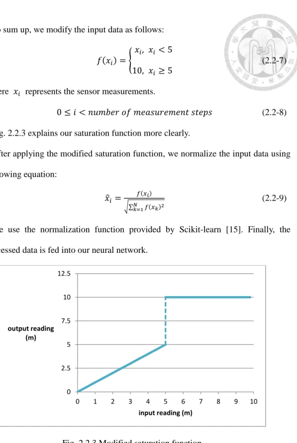
To sum up, we modify the input data as follows:
𝑓(𝑥𝑖) = {𝑥𝑖, 𝑥𝑖 < 5
10, 𝑥𝑖 ≥ 5 (2.2-7)
Here 𝑥𝑖 represents the sensor measurements.
0 ≤ 𝑖 < 𝑛𝑢𝑚𝑏𝑒𝑟 𝑜𝑓 𝑚𝑒𝑎𝑠𝑢𝑟𝑒𝑚𝑒𝑛𝑡 𝑠𝑡𝑒𝑝𝑠 (2.2-8) Fig. 2.2.3 explains our saturation function more clearly.
After applying the modified saturation function, we normalize the input data using the following equation:
𝑥̂𝑖 = 𝑓(𝑥𝑖)
√∑𝑁𝑘=1𝑓(𝑥𝑘)2 (2.2-9)
We use the normalization function provided by Scikit-learn [15]. Finally, the preprocessed data is fed into our neural network.
Fig. 2.2.3 Modified saturation function
2.2.3 Instruction Layer
This layer also consists of two stages: the speech recognition stage, and the
0 2.5 5 7.5 10 12.5
0 1 2 3 4 5 6 7 8 9 10
output reading (m)
input reading (m)
Speech Recognition 2.2.3.1
We implement the speech recognition stage to make our robot receive human instructions directly. Users can command the robot verbally instead of typing instructions into the remote computer.
In this research, we use the python package, SpeechRecognition, to implement our speech recognition function [16]. This package supports seven speech recognition engines and APIs, namely CMU Sphinx, Google Speech Recognition, Google Cloud Speech API, Wit.ai, Microsoft Bing Voice Recognition, Houndify API, and IBM Speech to Text. We choose to use Google Speech Recognition due to its ease of implementation and high recognition accuracy.
Verbal instruction inputted will be converted into text in this stage.
Conversion 2.2.3.2
The conversion stage first splits the input instruction into several shorter ones to handle the situation where the given instruction is too long and complex. The split instructions are called simple instructions, and they are inputted into the neural network sequentially. We will explain the method of splitting in the next chapter.
Before inputting a simple instruction into the neural network, the conversion stage converts each word in the instruction into vector. A pre-trained Global Vectors for Word Representation (GloVe) model is used here, and we decide to use a 100-dimension vector to represent one word [17]. We use the concept of word vectors to have our program consider the semantic information contained in user instructions.
For each simple instruction, we sequentially fed its word vectors into our neural network. The set of all word vectors of a simple instruction is called the sentence vector of that instruction.
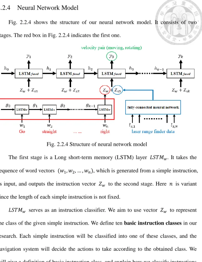
2.2.4 Neural Network Model
Fig. 2.2.4 shows the structure of our neural network model. It consists of two stages. The red box in Fig. 2.2.4 indicates the first one.
Fig. 2.2.4 Structure of neural network model
The first stage is a Long short-term memory (LSTM) layer 𝐿𝑆𝑇𝑀𝑤. It takes the sequence of word vectors (𝑤1, 𝑤2, … , 𝑤𝑛), which is generated from a simple instruction, as input, and outputs the instruction vector 𝑍𝑤 to the second stage. Here 𝑛 is variant since the length of each simple instruction is not fixed.
𝐿𝑆𝑇𝑀𝑤 serves as an instruction classifier. We aim to use vector 𝑍𝑤 to represent the class of the given simple instruction. We define ten basic instruction classes in our research. Each simple instruction will be classified into one of these classes, and the navigation system will decide the actions to take according to the obtained class. We will give a definition of basic instruction class, and explain how we classify instructions into ten classes in Chapter 3.
Since we aim to classify simple instructions into different classes, Softmax activation function is used in 𝐿𝑆𝑇𝑀𝑤:
The second stage combines a fully-connected neural network with another LSTM layer 𝐿𝑆𝑇𝑀𝑓𝑢𝑠𝑒𝑑. At time step 𝑖, the fully-connected neural network uses the sensor data (𝑙𝑖1, 𝑙𝑖2, … , 𝑙𝑖𝑁) from laser range finder to calculate its output 𝑍𝑠𝑖. 𝑁 denotes the number of measurement steps, and 𝑙𝑖𝑘 represents the kth sampling point. Next, 𝑍𝑤 and 𝑍𝑠𝑖 are concatenated and fed into 𝐿𝑆𝑇𝑀𝑓𝑢𝑠𝑒𝑑. The second LSTM layer will then calculate the velocity pair (moving, rotating) for controlling the mobile robot.
As for the activation functions, we choose to use ReLU in the fully-connected neural network, since all the input data from laser range finder are positive:
𝜎(𝒁)𝑖 = max (0, 𝑧𝑖) (2.2-11)
In 𝐿𝑆𝑇𝑀𝑓𝑢𝑠𝑒𝑑, we simply choose linear activation function since the outputs represent speeds and can be either positive or negative.
It should be noticed that the output of our neural network model will affect the input of it. That is, different velocity commands will lead the robot to different positions, and thus readings of the laser range finder will be different.
2.2.5 Post-processing Layer
The post-processing layer is composed of two functions: the speed adjusting function, and the halting counter.
Speed Adjusting Function 2.2.5.1
The speed adjusting function consists of two sub-functions. It is unlikely that the neural network will output pure zero. Therefore, when the output is below a certain value, we assume that the neural network is intending to stop the robot. We define the minimum value 𝑣𝑚𝑖𝑛 to be 10−3. The first sub-function changes either the moving velocity or rotating velocity to 0 when its absolute value is smaller than 𝑣𝑚𝑖𝑛.
The second sub-function prevents the navigation program from outputting
velocities which are too slow for the mobile robot to move with. Due to the physical constraints, such as friction, in real world, it is not possible for the robot to move with a speed which is below some certain value. However, when the output is above the minimum value 𝑣𝑚𝑖𝑛, we assume that the neural network is intending to move the robot.
Therefore, we need to increase the output velocity when the output lies in this range in order to make the robot move. We define the minimum moving velocity 𝑣𝑚𝑜𝑣𝑒 to be 2 ∗ 10−2. When the absolute value of output velocity is above 𝑣𝑚𝑖𝑛 and below 𝑣𝑚𝑜𝑣𝑒, the second sub-function will pull it up to 𝑣𝑚𝑜𝑣𝑒. This prevents the robot from getting stuck at the same position while the network is telling the robot to move.
To sum up, the speed adjusting function can be expressed by the following equation:
𝑓(𝑣) = {
0, |𝑣| ≤ 𝑣𝑚𝑖𝑛
𝑠𝑔𝑛(𝑣) ∗ 𝑣𝑚𝑜𝑣𝑒, 𝑣𝑚𝑖𝑛 < |𝑣| ≤ 𝑣𝑚𝑜𝑣𝑒 𝑣, 𝑜𝑡ℎ𝑒𝑟𝑤𝑖𝑠𝑒
(2.2-12)
Here 𝑣𝑚𝑖𝑛 = 10−3 and 𝑣𝑚𝑜𝑣𝑒= 2 ∗ 10−2, and 𝑣 represents the moving or rotating velocity outputted by the neural network model.
Halting Counter 2.2.5.2
This counter decides when the program stops. When completing the navigation process, the mobile robot should stop at its final position. Therefore, if the neural network model is trained well, our program should constantly output (𝑚𝑜𝑣𝑖𝑛𝑔, 𝑟𝑜𝑡𝑎𝑡𝑖𝑛𝑔) = (0, 0) after the robot reach its destination. We can assume that the robot has completed its navigation if the program continuously outputs (0, 0) for a number of time steps.
The halting counter counts the number of continuous zero outputs. If this number
layer and the conversion stage inside the instruction layer. The former will clear its memory, preparing to execute a new navigation task. The latter will load the next instruction into the network model. After that, the counter is set to zero, and the program continues the navigation. If there is no instruction left, the entire program stops.
In this research, we set the number of time steps to stop the process to be 50, which is approximately 5 seconds.
Chapter 3 Training Data Set
In this chapter, we will describe the training data set we use to train our neural network model. The training data set is composed of two parts: basic instruction sets, and human controlled navigating records. We will first describe the type of instructions we consider in our research. Next, we explain our method of generating the instruction training data set and that of collecting the navigation records. We will also introduce the teleoperation program we design for this research, and discuss the advantages of using such data structure for our training database.
3.1 Instruction
In the previous chapter, we have mentioned that we use laser range finder as the main sensor of our system. Despite the advantages we discussed, some information cannot be acquired by the laser range finder. For example, it is not easy to achieve object recognition using such sensor. Room number cannot be detected, either. Thus, we have to specify the instructions we consider in our research more clearly.
In short, we only consider instructions describing the structure of indoor environments. That is, aisles, corners and rooms are to be discussed. Higher level semantic instructions are not considered, such as room or aisle number, which needs more sensors to get enough information.
In our application, most of the given instructions are short and simple, like ‘Turn right, and then go straight to the end of the aisle.’ However, for cases with complex indoor environments, the longer the path that instructors command the robot to move, the more complex their instructions become. We consider it difficult for the robot to complete such complicated instructions, since it is not possible for the neural network to
‘remember’ so much information contained in the instruction. Therefore, our method is to split the original instruction into several shorter, simpler instructions.
After we divide the original instruction into many simple instructions, the goal of our navigation system is to make the mobile robot move to specific positions according to these simple instructions in sequence. To decide what actions to take for each simple instruction, we classify instructions into several classes. A basic instruction class is defined to be a set of simple instructions that have similar meanings. Each class has a basic instruction that represents the class. Fig. 3.1.1 and Table 3.1-1 show the ten basic instruction classes we define in this research, as well as their representative basic instructions.
Path / Class Number Representative Basic Instructions
1 Go straight to the end
2 Turn right
3 Turn left
4 Go back (turn around)
5 Turn right at the second corner 6 Turn left at the second corner 7 Turn right at the third corner 8 Turn left at the third corner
9 Go straight to the end and turn right 10 Go straight to the end and turn left
Table 3.1-1 Class of simple instructions
Fig. 3.1.1 Ten paths corresponding to ten classes of simple instructions
It should be noticed that the second basic instruction contains two different meanings: ‘Turn right immediately’, and ‘Turn right at the first corner’. So is the third instruction.
Since our application is under indoor environments, and we use laser range finder as the sensor, we assume that these ten basic instructions suffice to describe the sequential steps of conducting a complete navigation. That is, we can use these basic instructions to construct all the legal instructions we consider in this research. Therefore, all the simple instructions split out from the original instruction can be classified into one of these basic instruction classes.
Now we explain our method of splitting user commands into simple instructions.
Since each basic instruction contains enough information, it is not possible that a person may say such a long sentence containing more information than the basic instruction without a pause. Therefore, we simply use punctuation marks to split sentences into simple instruction.
The idea of splitting instruction into simple ones, converting each word into word vector to construct the sentence vectors for each simple instruction, and executing them sequentially can be described by Fig. 3.1.2. After completing the execution of some
executing these instructions sequentially, the robot will finally get to the location indicated by the original instruction.
Fig. 3.1.2 Example of executing a complex instruction
We collect ten sets of simple instructions corresponding to the above ten classes to train our model. These ten sets are called basic instruction sets, and each of them should be a subset of their corresponding basic instruction class. In the next section, we describe how we construct these ten sets.
3.2 Basic Instruction Sets
In Chapter 2, we mention that we design a neural network model that classifies verbal instructions into ten basic instruction classes. To construct a database for training such a classification model, a straightforward approach is to collect thousands of instructions and label them manually. However, there is no online instruction database that can be direct used for training our model. Most of the commonly used databases contain high-level semantic information, such as room numbers or features that can only be captured by camera. These instructions cannot be classified into any of our instruction classes. Besides, typing numerous different instructions will be a tedious work. Therefore, we design an algorithm that can generate instructions using small
To construct a sufficient training database, we first manually create sets of phrases.
Each of these sets plays a different role in constructing a complete instruction sentence.
While generating instructions, our algorithm chooses some of these sets, randomly picks one phrase from every chosen set, combines these phrases to form an instruction sentence, and labels the sentence according to the sets it chose. The process of generating a complete instruction sentence is described by Fig. 3.2.1. Each of the boxes represents a collection of phrases.
Fig. 3.2.1 Process of generating a complete instruction sentence The sets of phrases are as follows:
1. Prefix: Phrases or words that can be attached to the beginning of instruction sentences, without changing the meaning of instructions.
For example: ‘Please …’, ‘Would you …’, ‘I need you to …’
2. Suffix: Phrases or words that can be attached to the end of instruction sentences, without changing the meaning of instructions.
For example: ‘… please.’, ‘… and stop.’, ‘… thank you.’
4. Class Turn: Phrases used to construct Class 2, Class 3, and Class 5 to Class 10 instruction sentences. Phrases belonging to this set can be directly classified into Class 2 or Class 3 basic instruction, and appending phrases from the Suffix Turn set to their end may make them become Class 5 to Class 10 basic instruction.
For example: ‘turn right’, ‘make a left’
5. Prefix Turn: Phrases that can be attached to the front of phrases from Class Turn without changing the meaning of constructed instruction sentences.
For example: ‘go straight and’, ‘walk down this way and’
6. Suffix Turn:
There are two kinds of phrases that belong to this set:
A. Phrases that can be attached to the end of phrases from Class Turn without changing their classification. For instance, ‘turn right’ and ‘turn right at the corner’
both belong to Class 2 basic instruction.
For example: ‘at the corner’, ‘at the crossroad’
B. Phrases that can be attached to the end of phrases from Class Turn to change their classification, making them become Class 5 to Class 10 basic instruction. For instance, ‘turn right’ belongs to Class 2 basic instruction, but ‘turn right at the second corner’ belongs to Class 5 basic instruction.
For example: ‘at the second corner’, ‘at the end of this aisle’
7. Class 4: Phrases used to construct Class 4 instruction sentences.
For example: ‘go back’, ‘turn around’
8. Others: Phrases that cannot be classified into any of the above sets.
For example: ‘go straight to the end and turn right’
It should be noticed that we convert each word in the instruction into word vector
meaning of that word to a certain extent, we assume that our model can be trained successfully without having seen every word. Therefore, the collections of phrases do not need to contain every possible phrase.
Now, we give some examples of generating instruction sentences for our training database, i.e., the ten basic instruction sets.
Prefix + Class 1 + Suffix → Class 1 basic instruction
‘Could you’ + ‘go straight till the end’ + ‘please’ = ‘Go straight to the end’
Prefix Turn + Class Turn + Suffix → Class 2 basic instruction
‘Go straight and’ + ‘make a right turn’ + ‘please’ = ‘turn right’
Prefix + Class Turn + Suffix Turn → Class 5 basic instruction
‘Please’ + ‘make a right turn’ + ‘at the second intersection’ = ‘Turn right at the second corner’
For each basic instruction set, we consider all possible combinations of sets of phrases that generate sentences for it. This method greatly increases the amount of training data for training our neural network model. Experiments show that the classification accuracy of our model, as well as the ability to handle new, unfamiliar instructions is improved using such expanded database.
It should be noticed that some of the generated sentences are not grammatically correct. For example, the sentence ‘Please turn right please’ is not proper since the word
‘please’ is used twice. However, we consider that including such sentences in our training database is legal.
Our neural network model does not need to know what kinds of instructions are grammatically correct. Its function is to classify instructions, extracting semantic
class of basic instruction, we consider it useful in training. Besides, people often use incorrect grammar when speaking. Using such sentences in our training database gives our model the ability to handle the variety and complexity of verbal instructions.
3.3 Human-Controlled Navigating Records
3.3.1 Database
A human-controlled navigating record is a set of recording sequences. Each recording sequence contains hundreds of sampling data, where every sampling data consists of the velocity of the robot and readings of its laser range finder at that sampling moment. One recording sequence is considered as one training data sequence.
While collecting training data, we let a person remote robot to the destination according to a specific basic instruction, and during the navigation we collect the (𝑣𝑒𝑙𝑜𝑐𝑖𝑡𝑦, 𝑚𝑒𝑎𝑠𝑢𝑟𝑒𝑚𝑒𝑛𝑡) pairs. By doing so we obtain a sequence that describe the expected behavior of a robot after receiving an instruction.
Fig. 3.3.1 shows an example of our recording files. An indicator is added to the beginning of every recording sequence, while another one is used at the end of each sequence. In Fig. 3.3.1 we use red box and blue box to annotate the starting and ending indicator. The starting indicator also shows the class of the recording sequence.
The yellow underline in Fig. 3.3.1 shows an example of a sampling data. The former part is the (moving, rotating) velocity pair, while the latter part is the measurements from laser range finder. After preprocessing the latter part is used as part of the input of our neural network, while the former part serves as the referenced label during training process.
Fig. 3.3.1 Example of the recording files
3.3.2 Teleoperation Program
To collect human-controlled navigating records, we give users some basic instructions and record the (velocity, measurement) pairs during their navigation. To fulfill such task, a teleportation program is required to let the user control and navigate the robot. Since we develop our navigation system on ROS, a straightforward method is to use the ROS node teleop_twist_keyboard [14]. However, it is hard to perform natural navigation using such program due to its maneuverability. To let the user navigate the robot smoothly, we design our unique teleoperation program.
We first describe the disadvantages of using teleop_twist_keyboard as the teleportation program. Fig. 3.3.2 shows the control method of teleop_twist_keyboard.
Eight keys are used to control the direction of moving, while six keys are used for adjusting the speed. Some problems of using this program are as follows:
If you want the robot to move continuously, you need to hold the keys. Pressing the key once will make the robot move for a small distance and stop.
robot is moving straight, controlling it to rotate is difficult.
Extra keys are needed to adjust the speed of moving. It will be tedious to gradually slow down or speed up the robot.
The control is not intuitive. Using arrow keys will be much better.
Fig. 3.3.2 Control method of teleop_twist_keyboard
To solve the above questions, we develop our teleoperation program. Its control method is shown in Fig. 3.3.3.
It should be noticed that the robot rotates only when the user is holding the Left or Right key. For example, although the rotating velocity gradually increases when the user holds the Left key, it will be set to 0 when user releases the button. Therefore, the robot will not keep rotating once you press the arrow key.
The advantages of our program are as follows:
Only five keys are used. Arrow keys are used to control the direction and speed of the robot, and user can directly adjust the moving and rotating velocity. Therefore, the control is more intuitive.
When the user wants to accelerate the robot, he can hold the Up key to gradually speed up. User can also slightly adjust robot’s moving speed.
can make the robot rotate and turn left or right. While rotating the robot, releasing the Left or Right key will stop its rotation.
You do not need to hold the keys to make the robot move continuously. After pressing the Up key, the robot will continue moving until moving velocity is decreased.
Fig. 3.3.3 Control keys of our teleoperation program
By using such teleoperation program, it will be much easier to control the robot and collect the navigation records for training database. Natural navigation can also be achieved.
3.4 Features and Advantages
As mentioned before, our training data set consists of the human-controlled navigating records and ten basic instructions sets. All instructions in each basic instruction set have similar meanings, and can be represented by the basic instruction of that set. Each recording sequence contains a sequence of (𝑣𝑒𝑙𝑜𝑐𝑖𝑡𝑦, 𝑚𝑒𝑎𝑠𝑢𝑟𝑒𝑚𝑒𝑛𝑡) pairs, and is collected according to some basic instruction.
During training process, the neural network model uses measurement as part of the input—the other part comes from basic instructions sets—and the velocity as referenced labels. This model tries to make its outputs correspond to the reference velocities given
readings of its sensor at that moment and the given initial instruction. It can be expected that the robot will move smoothly as if there is a person controlling it.
While training neural network model, for instance if we want to train the ‘turn right’
instruction, our algorithm will randomly pick one instruction from the ‘turn right’ basic instruction set, convert it into sentence vector, and use the vector as part of the input.
For one training data sequence, this sentence vector will be fixed; however, for one recording sequence, we may pick different instructions from the same set, and thus would obtain different training input. By doing so, we make great use of the navigating records. For example, supposing we records 1,000 sequences for the ‘turn left’
instructions, and we construct its instruction set to have 100 instructions. By combining these two we obtain 100,000 different training sequences, and thus we could gather huge amount of training data using fewer recording sequences.
Another benefit of using such data structure for our training database is that we can easily add more instructions into the instruction sets to extend them, without having to collect the training data sequences again. Also, when recording new training sequences, there is no need to give a precise instruction. We will only need to specify the class of basic instructions being executed. Therefore, it would be much easier to expand the training data set. This method also gives good extensibility to the model. In this paper we classify simple instructions into ten basic instruction classes. If we want to add more classes of basic instructions into the original model, we only need to construct a new set of instructions, and records new sequences to train the model.